How SMD components are soldered. Soldering smd components is easy!! how to solder smd components
Installation and soldering of SMD elements at home - in our time, the assembly of electronic devices on SMD components, designed for installation on the surface of the board, is becoming increasingly popular. This installation technology is due to the most dense arrangement of parts, and in terms of economics it is technologically cheap production. On the Internet you can find many articles on the methods of mounting such electronic components, but each radio amateur has his own ways of working with SMD parts, so in my article I want to share my skills in surface mounting electronic parts with both beginner radio amateurs and those godfathers have not yet had a chance to work with SMD.
Attention! All images are clickable.
Necessary tools and materials
A little about the tools and materials that will be required in the process. There must be good tweezers, a needle (you can use a syringe), to apply the flux you will need a syringe with a thick needle, wire cutters, low-melting solder, and since the parts themselves are miniature and it is difficult to work with them with the naked eye, so you will also need a magnifying glass. And ideally, it would not be bad to have a device such as a head magnifier, for example, of this brand: MG81001-3LED is a magnifying glass with a set of three-dimensional lenses and built-in LED backlight. And you should also have a liquid flux, for example F-3 or self-prepared from pure rosin powder and alcohol, but it is still recommended to use commercially produced fluxes, their choice is huge on sale.

In domestic conditions, it is most preferable to solder SMD parts with hot air; for this, there are special soldering stations, and an electric dryer is installed instead of a conventional soldering iron. Such equipment is now on sale in large quantities, and if it is made in China, then the prices are low. Here, the photo shows such a Chinese device, the name is difficult to pronounce, but this station has been operating for about three years and so far has been trouble-free.

Naturally, you will not need a large soldering iron with a thin tip, where without it? The advantage here is given to a set of soldering tips "Microwave", manufactured according to the technology of the German company Ersa with 80 years of experience. The kit contains a tip of various shapes and purposes, a more common design is a tip with an internal recess, in which a metered amount of solder accumulates and is convenient when working with densely packed parts, and the likelihood of sticking between closely spaced microcircuit pins is also reduced. Be sure to purchase a set of replacement soldering tips that will make soldering much easier for you. In cases where you have not yet acquired such tips, then you can also solder with an ordinary thin conical tip.

On factory conveyors, the installation of SMD parts is carried out by applying a special paste to the board, then with the help of robots the components are placed in their mounting places, thereby sticking to the solder paste and sent to a thermal furnace along the conveyor. The boards are heated to a predetermined temperature in the furnace. During the heating process, the flux from the solder paste evaporates, and the solder melts to form a reliable contact connection between the part and the printed circuit board.

Based on factory technologies, you can try to reproduce these works in a home workshop. I think it will not be difficult to buy solder paste now, since it is available in electronics stores and on radio markets in a wide range. To apply the paste on the board in a metered amount, you need to use a thin needle from a syringe. I think the most suitable option would be to use the syringe itself, into which the paste is drawn, and then squeezed out onto the contact pads of the board. The photo shows how not to do it, that is, too much paste is squeezed out, especially on the left side of the board.

Nevertheless, we continue to work on installing components. We place parts on the pads with applied paste, at the moment these are capacitors and resistors. At this stage of the layout, tweezers are indispensable, and the tweezers should preferably be with curved ends, for example, it is more convenient for me to use this.

For a one-time installation of parts, you can of course do without tweezers, say, take a toothpick, and grease its tip with some kind of sticky substance, you can use the same flux, then it is quite possible to install the component on the site. It's just who how to adapt.
After completing the layout of the parts and placing them in their intended places, the process of heating with hot air begins. Low-melting solder begins to melt at a temperature of +178°С, and the temperature of hot air must be set by the regulator on the soldering station within +250°С, then, placing the tip of the hot air gun at a distance of about 100 mm, begin to carefully heat the board while gradually bringing the hot air nozzle closer to pay. You need to be more careful with the pressure of the hot air flow, in cases of its strong pressure, there is a high probability of blowing off all the parts from the board. As in industrial production, in a heating furnace, the flux evaporates when heated, and the solder changes its color as it melts, and gradually turns from dark to light and shiny. The picture below shows exactly the moment of its melting.

After the solder is melted, the hot air gun nozzle should be slowly removed from the surface of the printed circuit board, thereby allowing it to cool. The photo shows what ended up happening. Studies have shown that large drops of solder at the ends of the parts indicate that there is too much paste in these places, and where there is little solder, it means there was not enough paste.

It may happen that solder paste is not available in your region or it is too expensive for you, that is, a soldering option without using paste. This method will be shown in the photo, and a microcircuit will serve as an example. First, you need to cover all the sites where the components will be installed with a thick layer of solder, that is, apply tinning.

The pictures should show that the contact pads are covered with solder so that they form a kind of tubercle. Here, one of the important conditions is the uniform application of solder to all sites, that is, the height of the tubercles should be the same. After you have tinned, we drip a little flux from the syringe onto the installation sites of the elements and wait a bit until it thickens. In this state, it will be easier for SMD parts to stick to the flux. With special care, using tweezers, we install the microcircuit in the place allotted for it. To combine the pins of the microcircuit with the pads on the board, this is already a matter of principle.

Near the microcircuit, I placed a number of passive elements, ceramic and polar capacitors. In order to avoid parts falling out from the board under the influence of a hot air jet from a hair dryer, we begin to heat the board as already mentioned above, with the hair dryer nozzle slightly removed from the surface of the parts. The main thing is not to rush with warming up, not an accurate movement of the air stream and small parts will all scatter.

Here's a look at what happened as a result of these actions. The picture shows that the containers are soldered, as it should be, but several legs of the microcircuit, marked in red, were not soldered. This marriage can be caused by several reasons, such as not enough solder on the pads or not enough flux was applied. This is corrected with an ordinary soldering iron with a thin conical tip. You need to add a little flux to the pad again and solder with the addition of solder. To prevent such defects, you should always use a magnifying glass.

For those radio amateurs who do not have a soldering station, you can get by, as mentioned above, with a simple soldering iron. Below, the pictures show examples of soldering resistors and two microcircuits using a soldering iron. The first example will be a resistor. We install a resistor on pre-prepared contact pads, that is, already with solder and flux applied to them. To avoid its shift during soldering, it must be pressed with an awl or needle.

Next, a short touch with the tip of the soldering iron on the output of the part on the site is enough and the component will immediately be soldered. Try not to pick up solder with a soldering iron tip very much, otherwise, due to excess solder leakage may occur relative to adjacent leads or tracks.
Here is the result of soldering the resistor

The quality certainly leaves much to be desired, but it is reliable. The decrease in soldering quality is due to the inconvenience of simultaneously soldering, pressing the resistor and taking a photo, that is, the problem is the lack of a “third hand”.
The remaining electronic components are soldered in a similar way. As for me, at first I solder the base of a powerful transistor to the contact pad, while I do not save solder. Parts of the solder must flow under the body of the semiconductor, which will create an additional reliable electrical and thermal contact.

So that there is no doubt about the reliability of the soldering, then when you start to solder the part, move the transistor case with a needle, it should slide a little, this proves that the solder under the case has completely melted, and the excess is squeezed out, thereby improving thermal contact. The picture shows an already soldered stabilizer chip.


After soldering one leg, you need to once again check the accuracy of the installation of the microcircuit and the coincidence of its legs with the pads, and then we solder the rest of the leads along the edges.

Now the chip is securely fixed on four sides. Being careful, we solder the remaining legs, while making sure not to make jumpers with solder between the pins of the microcircuit.

At this stage of work, the tip for the “microwave” soldering iron will help a lot, it was mentioned at the beginning of the article. Using this tip, you can easily solder microcircuit assemblies with a large number of pins, in a fairly easy way, just run the soldering iron tip along the legs of the microcircuit. Jumpers between pins are very rare, and it takes about a minute to solder a chip with more than fifty pins on one side. This is such an amazing sting. Well, if you don’t have it, then do the work with a simple conical tip, but very carefully.

If there was such an unpleasant moment as soldering several pins of the microcircuit together, it is always problematic to remove these jumpers with only one soldering iron.

Then you can remove them using a piece of braid taken from a shielded wire. The braid must be placed in a container with flux so that it is saturated, and then applied to the problem area with an influx of solder and a soldering iron to heat the solder through this braid.

All excess solder will be absorbed into the braid, and the pad and the gap between the pins of the microcircuit will remain clean and free from unnecessary sticking.

At the end of the article, it remains to be hoped that this post was at least a little useful to you. And the quality of the photographs did not irritate you, since the photos were taken simultaneously with soldering. Good luck with your electronic business!
SMD components are small electronic components that are mounted on the surface of a printed circuit board. "SMD" (in transcription "SMD") is an abbreviation of the phrase from the English language "Surface Mounted Device", which translates as "a device mounted on a surface."
Another meaning of the word "surface" is that soldering is not done in the traditional way, when the leads of the components are inserted into the hole of the printed circuit board and soldered to the conductive tracks on the reverse side. SMD components are mounted on the front side, where all the tracks are located. This type of fit is called surface mounting.
SMD components, thanks to the latest technology, have a small size and weight. Any small element that functionally contains tens or even hundreds of resistors, capacitors and transistors will be several times smaller than an ordinary semiconductor diode.
As a result, radio-electronic devices made from surface-mounted components are very compact and lightweight.
The small size of SMD components does not create conditions for the occurrence of induced currents in the elements themselves. For this case, they are too small and do not affect performance. As a result, devices assembled on such parts work better, without creating interference and not reacting to interference from other devices.

SMD components can be placed very close to each other on the board. Modern parts are so small that most of the space began to be occupied by conductive paths, and not by radio components. This prompted manufacturers to make circuit boards multi-layered. They are like a sandwich of several boards, only the contacts from all the tracks are brought to the surface of the topmost of them. These contacts are called mounting patches. Such multilayer boards are very compact. They are used in the manufacture of mobile phones, smartphones, tablet computers. The details on them are so small that they can often be seen only under a microscope.
Soldering technology
As mentioned above, the soldering of SMD components is carried out directly on the surface of the mounting patches. Very often, the conclusions of the parts after installation are not even visible. Therefore, the use of a traditional soldering iron is not possible.
Soldering SMD components is carried out in one of several ways:
- heating the entire board in the oven;
- using an infrared soldering iron;
- using a hot air soldering iron or hair dryer.
When devices using SMD components are manufactured by industrial methods, special automatic robots are used. In this case, solder has already been pre-applied on the mounting patches in an amount sufficient for mounting. In other cases, during preparation, solder paste for SMD components is applied over the stencil. The robot arm puts the parts in place and securely fixes them. After that, the boards with installed SMD components are sent to the oven.
The temperature in the furnace is gradually increased to a certain value, at which the solder is melted. For the material from which boards and radio components are made, this temperature is not dangerous. After all the solder is melted, the temperature is lowered. The decrease is carried out smoothly according to a certain program determined by the thermal profile. It is with this cooling, and not with sudden cooling, that the soldering will be the most durable.
Board preparation at home
To solder SMD components with high quality in a home workshop, you will need an infrared soldering iron or a hot air station. Before soldering, be sure to prepare the board. To do this, it must be cleaned and irradiated patches. If the board is new and has never been used anywhere, you can clean it with an ordinary eraser. After that, it is necessary to degrease the surface by applying flux. If it is old, and there is dirt and remnants of the old solder on it, you can prepare it with fine-grained sandpaper, also degreasing after cleaning with flux.
Soldering SMD components with a conventional soldering iron is not very convenient due to the small size of the pads. But if there is no soldering station, then you can also use a soldering iron with a thin tip, working with it carefully, picking up solder on a heated tip and quickly touching the contact.
Paste application
To solder microcircuits with high quality, it is better to use not solder, but solder paste. To do this, the element must be placed on the board and fixed. Of the tools, tweezers, plastic clamps, small clamps are used. When the leads of the SMD component are exactly on the mounting patches, solder paste is applied to them. To do this, you can use a toothpick, a thin brush or a medical syringe.


You can apply the composition without worrying that it covers the surface of the board around the mounting patches. During heating, surface tension forces will collect it into drops and localize it at the places of future contacts of the SMD component with the tracks.
warming up
After application, it is necessary to heat the installation area with an infrared soldering iron or a hair dryer (temperature approx. 250 °C). The soldering composition should melt and spread over the contacts of the mounted component and the patch. The power of the blow dryer must be adjusted so that it does not blow away drops of solder paste from the board. If the characteristics of the device used for soldering allow, the temperature should be reduced gradually. It is not allowed to accelerate cooling by blowing air over the contacts of SMD components.
The same technology is used for soldering LEDs, in case of replacing burned-out elements in any lamp or, for example, in instrument lighting. The only difference is that during soldering, the board must be heated from the side opposite to the one on which the components are installed.
Types of solder pastes
 Solder paste is the best tool for automated soldering of SMD components. It is a viscous low-flowing flux substance, in which the smallest particles of solder are contained in suspension.
To be able to use it successfully, the paste must meet certain requirements:
- should not oxidize and exfoliate into components;
- must have a certain viscosity, that is, be liquid enough to melt from heating, and at the same time thick enough not to spread over the entire board;
- should not leave dirt and slag at the place of soldering;
- the paste should be well washed with common solvents.

According to the method of use, the compositions are divided into washable and non-washable. As the name implies, the remaining cleaning paste must be removed from the soldering area after completion, otherwise the components included in it can attack the traces and leads of the parts. No-clean compounds can remain after soldering, as they are completely neutral to the materials of boards and SMD components.
Washing agents, in turn, can be water-soluble and halogen-containing. Water soluble cleaners can be washed off the boards with deionized water.

Washing pastes sometimes contain halogens. They are introduced into the composition to improve performance properties. Halogen-containing pastes can be used for high speed printing or, conversely, where a very long setting time is required. Soldering properties are also improved by the introduction of halogens. Halogen-containing pastes are washed off with solvents.
DIY soldering paste
 There are many brands and types of solder pastes on the market that meet all the conditions and requirements necessary for high-quality installation.
At home, you can make such a composition, having a hard solder bar, solder fat and flux on hand.
Solder must be crushed into a very fine fraction. This can be done with a file or sandpaper. The resulting dust from the tin-lead rod must be collected in a small container and mechanically mixed with soldering fat. If soldering fat is not at hand, you can use any liquid flux, and use ordinary petroleum jelly as a binder and thickener.
The consistency of the paste can be determined by eye, roughly calculating the proportions. The finished composition can be kept in a small plastic container with a tight-fitting lid. It is even better to load it into a regular medical syringe with a thick needle.
If you squeeze out the paste in a dosed manner at the place of future soldering, it will be very convenient to use such a paste, and the result will be durable and reliable.
Perhaps you are horrified by the small size of SMD components that are commonly used in modern electronics. But you shouldn't be afraid of this! Contrary to popular belief, soldering SMD components is much easier than soldering THT elements (Through-hole Technology, THT - through-hole technology).
SMD components undoubtedly have many advantages:
- low price;
- small size - more elements can be placed on one surface;
- no holes need to be drilled, and in extreme cases nothing needs to be drilled at all;
- all soldering takes place on one side, and there is no need to constantly turn it over;
So, let's see what we need to solder SMD components:
- Soldering iron - a regular, inexpensive soldering iron will do.
- Tweezers - you can buy at the pharmacy.
- Thin solder - for example, with a diameter of 0.5 mm.
- Flux - rosin dissolved in ethyl alcohol or you can buy a ready-made flux in a syringe for soldering SMD parts.
So what? It's all? Yes! Soldering most SMD components does not require any special equipment!
Soldering SMD packages 1206, 0805, MELF, MINIMELF, etc.
Resistors, capacitors, diodes and LEDs are produced in these cases. Such elements are supplied in paper or plastic tapes adapted to automatic assembly. Such tapes are wound on drums and usually contain 5,000 pieces of elements, although perhaps even 20,000 in one reel.
Such coils are installed in assembly machines, so that the entire production process can be fully automated. The role of a person in such production is only the installation of new coils and quality control of the finished product.
The package name encodes the dimensions of the SMD component. For example, 1206 means the element is 120 mils long and 60 mils wide. Mils is 1/1000 of an inch or 0.0254 mm.
In practice, the most commonly used cases are 1206, 0805, 0603, 0402, 0201, 01005. For manual mounting, the 1206 case is ideal, but even 0402 can be soldered by hand, although this is quite tedious. MELF elements are cylindrical and are most often diodes or resistors. Let's get down to business now!
Solder the diode in the MELF package
First of all, we must irradiate one of the pads. We process the pad with flux and touch it with the tip of the soldering iron, and after a while we apply solder. The solder should melt immediately and evenly cover the entire area. All you need is a thin layer of solder - it's better to have too little than too much.


Next, we take the SMD component by the sides and put it in place to be soldered. After that, you should heat up the previously tinned area and press the SMD component into it. The solder should evenly cover the lead of the components.


The last step is soldering the second contact. There is nothing complicated here - we touch the contact and the site with a soldering iron tip, then apply solder to it, which quickly melts, enveloping the soldering place in an even layer.


The following figures show how the capacitor is soldered into the 1206 package. The sequence of operations is identical to the above.


SMD soldering in SO8, SO14, SO28 package, etc.
Most simple integrated circuits are found in SO packages, such as logic gates, registers, multiplexers, operational amplifiers, and comparators. They have a relatively large pin pitch: 50mils. You can easily solder them without special equipment.
The first step is tinning the contact pad located in one of the corners. We touch the pad with a soldering iron, heat it up, and then apply some solder.


Next, take the microcircuit with tweezers and put it in the place of soldering. Similar to the 1206 example, we heat up the tinned field so that the microcircuit sticks to the board. If the microcircuit has moved, then warm up the contact again and adjust its position.

If the microcircuit is installed correctly and is held securely, then we solder the remaining legs. We apply a soldering iron tip to them, warm them up, and then touch them with solder, which, when melted, envelops them. Flux should be used to improve soldering quality.


Soldering SMD packages TQFP32, TQFP44, TQFP64, etc.
In principle, the components in the TQFP package can also be soldered without flux, just like SO, but we want to demonstrate here what the active flux gives. You can buy it in syringes labeled FLUX.

In the following example, we will solder the chip into the TQFP44 package.
Let's start by lubricating all the solder pads with flux. The flux has a thick consistency and is very sticky. Be careful not to get dirty because you can only clean it with solvent.


We will not pre-serve, as we wrote earlier. We put the chip immediately in its place and install it in the correct position.

Prior to this, soldering was carried out with a sharp sting. Now we will demonstrate soldering with a knife-shaped sting, which can simultaneously solder several legs at once.

We collect a little solder on the tip of the sting, and then touch the two legs in opposite corners of the microcircuit. Thus, we fix the microcircuit so that it does not move when soldering the remaining legs.

Now it is important to have a small amount of solder on the tip of the soldering iron. If there is a lot of it, wipe the sting with a damp sponge. We touch the tip of the sting of the legs that have not yet been soldered. You should not be afraid of shorting the legs, because thanks to the use of an active flux, this can be avoided.


If, nevertheless, somewhere there was a short circuit of the legs with solder, then it is enough to clean the soldering iron tip, and then distribute the solder over the adjacent legs, or even remove it to the side.
In conclusion, you need to wash off the active flux, as after a while it can oxidize the copper on the board. To do this, you can use ethyl or isopropyl alcohol.
This article will cover a small instructions for soldering smd components. You will learn how to solder many-legged microcircuits, as well as get acquainted with the main points and possible difficulties that may arise during the soldering process and learn how to avoid them. The article clearly shows how to solder SMD components, and also talks about the necessary equipment and solders, I hope I hope it will be useful!
Every day, more and more radio amateurs use SMD parts and components in their work. Despite their size, they are easier to work with: no need to drill holes in the board, bite off long leads, etc. Mastering the soldering of SMD components is a must, as it will definitely come in handy.
This master class is not intended for beginners in soldering, but rather for amateurs who are good at soldering but have little difficulty with soldering many-legged microcircuits or controllers.
What you need to solder SMD components
-
Buy a soldering iron with temperature control
Tip Cleaning Sponge
Buy a sponge for cleaning the sting

-
Buy braid for desoldering

-
Buy tweezers

Solder tubular or other
Buy solder

-
Buy flux paste

-
Buy liquid flux

And the best buy a ready-made kit for soldering SMD components where you will find all the necessary tools and accessories.
Buy SMD Soldering Kit

This is a minimal set, without expensive soldering stations, hair dryers and desoldering pumps.
We solder SMD components with our own hands
So, let's start with the most difficult part - soldering the controller in the QFP100 package. With chip resistors and capacitors, I think everything is clear. The main rule here is: there is no such thing as a lot of flux, or you cannot spoil the soldering with flux. Excessive application of the flux prevents the tin from spreading abundantly over the contacts and closing them. There is also a second secondary rule: even a little solder can be a lot. In general, you need to dose and apply it to the sting very carefully so as not to overdo it, otherwise it will flood everything at once.
Site tinning
Experienced radio amateurs do not always take this step, but I recommend doing it in the first couple.
It is necessary to tin the board, namely the place where the controller will be soldered. Of course, the site is most likely tinned, especially if the board is made in production. But over time, an oxide film appears on the contacts, which can interfere with you. We heat the soldering iron to operating temperature. We generously lubricate the site with flux. We put a little solder on the tip and tin the tracks.

Excess solder is removed with the help of a PS wire. It perfectly absorbs solder due to the effect of capillarity.

Installing and aligning the controller
With the site ready, it's time to install the controller. There is a trick here, most solderers install a microcircuit and align its contacts along the tracks with tweezers. But this is very difficult to do, since even a slight twitch of the hand throws the controller a considerable distance. It will be much easier to do this if you lubricate the corners diagonally with flux paste.

Now install the controller and adjust with tweezers.

As soon as the microcircuit has risen, we solder the contacts diagonally.

Check if all contacts are in place.
Soldering SMD contacts of the microcircuit
Here you can already use both liquid and viscous flux. We apply it very liberally to contacts.

Wet the tip with a drop of solder, clean the excess with a sponge.

And, carefully run over the lubricated contacts.

There is no need to hurry in this matter.

Removal of excess flux and solder
After soldering all the contacts, it's time to remove the excess solder. Surely several contacts, but stuck together.


Wet the contacts very liberally with liquid flux. We completely clean the tip of the soldering iron with a sponge from solder and go through the sticky contacts. Excess solder should be drawn onto the tip. To remove excess flux, use SBS - an alcohol-gasoline mixture mixed 1: 1.
We wet abundantly.

And thoroughly wipe everything!

Be sure to watch the video, where you can clearly see the movement of the soldering iron and all the manipulations.
Even if you never have to deal with chip parts on your own, you need to understand that 99% of all modern electronics are created on their basis. Therefore, every self-respecting radio amateur should, at least in general terms, represent the SMD process technology.
In the previous lesson, we already got acquainted with the so-called SMD components (chip components). Now it's time to learn how they are mounted and soldered.
You can solder an SMD part using the most common solder and a soldering iron with a thin tip. The process consists of three steps:
We apply solder to one contact pad;
- using tweezers, set the chip component to the desired position and, holding the part with tweezers, warm up one of its outputs. The part is fixed, the tweezers can be removed;
- solder the second output of the component.
Manual soldering of SMD components
In approximately the same way, you can solder SMD transistors and microcircuits.
But manual soldering is a very long and painstaking process, therefore it is used only by radio amateurs to create single designs. At large radio factories, they are trying to automate everything. Therefore, there no one solderes each part individually with a soldering iron, the process is completely different.
You already know what solder is: a flexible tin-lead wire that melts when heated with a soldering iron, and after cooling it solidifies and securely fixes the output of the radio component, while providing electrical contact. But solder can be not only in the form of a tin-lead rod. You can create solder in the form of a paste, which is called solder paste. The paste contains in its composition both flux and the smallest particles of tin. When heated, the paste melts, and after cooling it solidifies, providing electrical and mechanical contact.
Solder paste is applied to all pads. In the production of prototypes and small batches, the paste is applied using manual dispensers: with a syringe, for example, or even with a toothpick. But in large-scale production, a different paste application technology is used. First, a stencil is made: a thin sheet of stainless steel, which has holes that exactly match the contact pads of the printed circuit board. The stencil is pressed against the printed circuit board, a layer of solder paste is applied on top and leveled with a special spatula. Then the stencil rises, and thus, in just a couple of seconds, the solder paste is applied to all contacts of the printed circuit board.

Printed circuit board with solder paste applied to the contact pads
You can now install components on the board. The SMD component can be neatly installed on the desired pads. In amateur radio, the installation of components is done manually using conventional or vacuum tweezers, and in large industries this operation is performed by robots that can install up to several hundred parts per minute! Due to the fact that the solder paste is viscous, the component seems to be fixed in place, and this is very convenient.
After installing all the SMD components, the board is soldered. The board is placed in a special oven, where it heats up to about 300C in a few minutes. The solder paste melts, and after cooling, provides mechanical and electrical contact between the components. In order to avoid thermal shocks, it is important to adjust the thermal profile, that is, the rate of heating and cooling of the printed circuit board. In industry, special multi-zone furnaces are used, in each chamber of which a strictly specified temperature is maintained. The printed circuit board, moving along the conveyor, sequentially passes through all zones of the furnace.
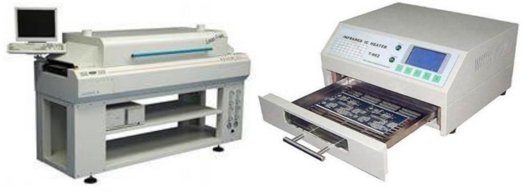
Soldering ovens: industrial (left) and for small-scale soldering (right)
In small-scale and pilot production, compact ovens are used, in which the boards are “baked” one at a time. Radio amateurs sometimes even adapt household ovens for this purpose, or heat the printed circuit board with hot air using an industrial hair dryer. Of course, the quality of soldering with such artisanal methods is very unstable, but the requirements for the reliability of amateur radio structures are usually not high.
After soldering is completed, the board is washed from the flux residues that are part of the solder paste, dried and checked. If there are DIP components in the design, they are soldered last, and even in large radio factories, this process is usually done manually. The fact is that it is very difficult and expensive to automate the DIP process, which is why modern radio electronics are mainly designed on SMD components.