Hc sr04 description. HC-SR04 Ultrasonic Distance Measurement Module. Necessary components for connecting an ultrasonic rangefinder
W1209 DC Temperature Controller, Relay Module, HC-SR501 Motion Sensor, ESP8266-12E Wi-Fi Module, HC-SR501 Motion Sensor, Power Supply, Brushed Motor Controller IC, IR Remote Control, NRF24L01 Radio Module, OKI 120A2, SD Card Module , Brushed motor controller IC, M590E GSM GPRS modem, Real time clock DS 3231/DS 1307, Mini 360 on LM2596 diagram, L293D, Infrared distance sensors, Real time clock, HC-SR501, Mini 360 power supply on LM2596 diagram, Controller L298N , HC-SR501, GSM GPRS, M590E GSM GPRS Modem, DS 3231/DS 1307 Real Time Clock, ESP8266-12E Wi-Fi Module, Card Module, Power Supply, Mini 360, L293D, Mini 360 Power Supply on LM2596 scheme, Radio Module , IR Remote Control, IR Remote Control, Ethernet shield, Brushed Motor Controller IC, Brushed Motor Controller IC, IR Remote Control, SD Card Module, NRF24L01 Radio Module, e OKI motor, L293D, Stepper motor, Power supply, L293D, Mini 360 power supply on LM2596 scheme, SD memory card, Ethernet shield, motion sensor HC-SR501, Wi-Fi module ESP8266-12E, OKI 120A2 stepper motor, Stepper motor,
Ultrasonic Distance Meters HC-SR04
Let's get acquainted with the distance sensors that will be useful in the projects discussed in the following chapters. The HC-SR04 ultrasonic rangefinder is a receiver and transmitter of an ultrasonic signal placed on the same board. In addition to the receiver and transmitter themselves, the board also contains the necessary strapping to make working with this sensor simple and easy.
 |
|
 |
|
The sensor has low power consumption, which is also an important advantage in the case of mobile robots that are not tied to a power outlet. The HC-SR04 sensor is powered by 5 V, which is also convenient when connecting it to the Arduino.
Specifications of ultrasonic range finder HC-SR04:
Measured range - from 2 to 500 cm;
Accuracy - 0.3 cm;
Viewing angle -< 15 °;
Supply voltage - 5 V.
The sensor has 4 outputs of the 2.54 mm standard:
VCC - power supply +5 V;
Trig (T) - input signal output;
Echo (R) - output signal output;
GND is ground.
Checking the operation of the sensor
Upload the program
sketch code
/* Sketch with the NewPing library, which can also be used for the HC-SR04 sensor
shown here SRF06 and allows you to connect ultrasonic sensors
with a single pin on the Arduino. You can additionally connect a 0.1 uF capacitor to the Echo and Trigger pins on the sensor. */
#include
#define TRIGGER_PIN 12 // Arduino pin tied to trigger pin on the ultrasonic sensor.
#define ECHO_PIN 11 // Arduino pin tied to echo pin on the ultrasonic sensor.
#define MAX_DISTANCE 200 // The maximum distance we control (in centimeters). The maximum distance of such sensors is in the range of 400-500cm.
NewPing sonar(TRIGGER_PIN, ECHO_PIN, MAX_DISTANCE); // Set up pins and maximum distance
void setup()(
Serial.begin(115200); // Open a serial protocol with a baud rate of 115200 bps.
}
void loop() (
delay(500); // Delay 500 milliseconds between wave generation. 29 milliseconds is the minimum allowed delay.
unsigned int uS = sonar.ping(); // Generate a signal, get the time in microseconds (uS).
Serial.print("ping: ");
Serial.print(uS / US_ROUNDTRIP_CM); // Convert time to distance and display the result (0 is out of range)
Serial.println("cm");
}
Open port monitor
Working Principle of HC-SR04 Ultrasonic Distance Meter
The rangefinder has two piezoelectric elements: one works as a signal emitter, the other as a receiver. The emitter generates a signal, which, reflected from the obstacle, falls on the receiver. By measuring the time it takes a signal to travel to an object and back, you can estimate the distance.
The sequence of actions is as follows:
- We apply a pulse with a duration of 10 μs to the output Trig.
- Inside the rangefinder, the input pulse is converted into 8 pulses at a frequency of 40 kHz and sent forward through the emitter T.
- Having reached the obstacle, the sent pulses are reflected and received by the receiver R, resulting in an output signal at the Echo pin.
- Directly on the controller side, we translate the received signal into a distance according to the formula:
Pulse width (µs) / 58 = distance (cm);
Pulse Width (µs) / 148 = Distance (inch).
Library Ultrasonic
For Arduino to work with the HC-SR04 sensor, there is a ready-made library - Ultrasonic. The Ultrasonic constructor takes two parameters: the numbers of the pins to which the Trig and Echo pins are connected, respectively:
ultrasonic ultrasonic(12,13);
here the output of the Trig sensor is connected to the 12th pin of the Arduino, and the Echo is connected to the 13th.
The library has one Ranging method, the parameter of which specifies whether to convert the distance to the object into centimeters or inches:
#define CM 1
#define INC 0
Thus, the line ultrasonic.Randing(CM) will return the distance to the object (of type long) in centimeters.
You can find the library files in the libraries/Ultrasonic folder of the electronic archive accompanying the book. To use the library in our projects, place it in the libraries folder of the Arduino installation directory.
The sketch that outputs the distance to the object in centimeters to the serial port is shown in the example.
sketch code
#include "Ultrasonic.h"
// sensor connected to:
// Trig - 12, Echo - 13 Ultrasonic ultrasonic(12, 13);
Serial.begin(9600);
float dist_cm = ultrasonic.Ranging(CM); Serial.println(dist_cm);
Connecting the HC-SR04 Sensor to the Arduino
The HC-SR04 ultrasonic sensor determines the distance and displays the obtained values in the serial monitor window in the Arduino IDE.
A small note: there is an excellent NewPing library freely available that makes the use of HC-SR04 even easier, an example of its use is also given below.// Generate a short LOW pulse to provide a "clean" HIGH pulse:
digitalWrite(trigPin, LOW);
delayMicroseconds(5);
digitalWrite(trigPin, HIGH);
delayMicroseconds(10);
digitalWrite(trigPin, LOW);
// Read data from ultrasonic sensor: HIGH value, which
// depends on duration (in microseconds) between sending
// acoustic wave and its return reception on the echo sounder.
pinMode(echoPin, INPUT);
duration = pulseIn(echoPin, HIGH);
// convert time to distance
cm = (duration/2) / 29.1;
inches = (duration/2) / 74;
Serial print(inches);
Serial.print("in, ");
Serial print(cm);
serial print("cm");
Serial.println();
sketch code
#include
#define TRIGGER_PIN 12
#define ECHO_PIN 11
#define MAX_DISTANCE 200
NewPing sonar(TRIGGER_PIN, ECHO_PIN, MAX_DISTANCE); // Set up pins and maximum distance.
Serial.begin(9600);
unsigned int uS = sonar.ping_cm();
Serial.print(uS);
Serial.println("cm");
If the HC-SR04 does not read the echo signal, the output signal will never be converted to LOW. Devantec and Parallax sensors provide a delay time of 36 milliseconds and 28 milliseconds, respectively. If you use the sketch above, the program will freeze for 1 second. Therefore, it is desirable to specify a delay parameter.
The HC-SR04 sensor does not perform well at distances greater than 10 feet. The pulse return time is about 20 milliseconds, so it is recommended in such cases to set the delay time to more than 20, for example, 25 or 30 milliseconds.
You can connect the ultrasonic distance sensor HC-SR04 to only one Arduino pin. To do this, you need to install a 2.2 kΩ resistor between the Trigger and Echo pins and connect only the Trigger pin to the Arduino.
To measure the distance to objects, you can use the HC-SR04 ultrasonic range finder, which works on the principle of a locator, like in bats. With the help of such a sensor, it is possible to design various robots that will go around obstacles, assemble circuits for automatically switching on lighting or other loads, and assemble an ultrasonic security system. The HC-SR04 rangefinder is a ready-made module that can be connected to various microcontrollers, I will conduct my examples together with the Chinese analogue of Arduino UNO.
On the front side of the sensor are two sensors, transmitting (T) and receiving (R). The transmitting sensor generates sound pulses at a frequency of 40 kHz. Having reached an obstacle, the impulse is reflected and captured by the receiving sensor. With sufficiently high accuracy, it is possible to determine the distance to the object, which can range from 2 cm to 4 m. The operation of the sensors is not affected by sunlight and the color of the object.

The electronics is located on the back of the sensor. Chip MAX3232 - controls the transmitting sensor. The LM324 operational amplifier amplifies the signal received from the receiving sensor.
To connect to the microcontroller, 4 pins are used:
Vcc– connects to the 5V pin of the Arduino.
trig– digital input, a logical unit is applied to it, with a duration of 10 μs. The transducer then transmits 8 cycles of an ultrasonic signal at a frequency of 40 kHz. When the reflected signal is received, the distance to the object will be calculated.
echo– digital output. A logical unit will be sent to it after the calculations are completed. Logical unit time, proportional to the measured distance.
Trig and Echo are connected to the digital pins of the Arduino, which ones are specified in the sketch.
Gnd– connects to the corresponding pin of the Arduino board.

Scheme of connecting HC-SR04 to Arduino, using the Chinese analogue Uno as an example.

Write to Arduino sketch #1, which will change the distance to the object. In the examples, pin " trig" is connected to pin 2 of the Uno, and the pin " echo» on 3 pin.
| int TrigPin = 2;// connect the Trig pin to the 2nd pin of the Arduino. int EchoPin = 3; // connect the Echo pin to the 3rd pin of the Arduino. void setup()( |
Line " duration = duration/29/2;» calculates the distance in « cm”, if you need to make calculations in inches, the line should look like this: “ duration = duration/74/2;».

The result of the sketch execution will be displayed in the serial port monitor window.
Sketch #2 turns on the LED built into the Uno board if the distance to the object is less than 50 cm. The LED hangs on pin 13.
| int TrigPin = 2; int EchoPin = 3; int LedPin = 13; void setup()( |
If, instead of an LED, we connect an incandescent lamp, as described in the article "", we will get a simple automatic lighting system. Having placed a similar design in some room, when a visitor enters the rangefinder coverage area, the light in the room will automatically turn on. The range finder quiescent current is less than 2 mA.
AT sketch #3 Let's replace the LED with a piezoelectric element (tweeter, buzzer), which will make a sound if the distance to the object is less than 50 cm. Thus, we get a simple sound radar or sound alarm.

Such "tweeters" are used in computers to alert the BIOS, as well as in children's toys with sound.

The connection scheme is simple, we connect the black wire of the buzzer to the GND pin of the arduino, the red wire to any free digital pin, with the PWM function (3,5,6,9,10,11,13). In the example, this is pin 5. We will connect the piezo emitter using the function analogWrite(). With this function, you cannot change the tone of the sound, the sound will be constantly at a frequency of about 980 Hz.
| int TrigPin = 2; int EchoPin = 3; int BeepPin = 5; void setup()( |
If the distance to the object is less than 50 cm, the buzzer will sound.
AT sketch #4 we will also use the buzzer, but only with the function tone(), which will allow you to change the tone of the sound, in different situations.
| int TrigPin = 2; int EchoPin = 3; int BeepPin = 5; void setup()( |
In line " tone(BeepPin, 500);" parameter " 500 " the sound frequency is set to 500 Hz. This parameter can be set from 31 Hz and up to the limits that the parameters of the piezo emitter and human hearing are limited to. This sketch will repeat the experiment of sketch No. 3, only using the tone () function, which will set the sound frequency.
AT sketch #5 Let's try to change the tone of the sound. At a distance of more than 50 cm, a sound will be emitted with a frequency of 1000 Hz. If the distance to the object is less than 50cm, the sound will change frequency by 500Hz.
| int TrigPin = 2; int EchoPin = 3; int BeepPin = 5; void setup()( |
Using the function tone() you need to pay attention to the fact that it interferes with the use of PWM on pins 3 and 11 of the Arduino, (this does not apply to the Mega platform). Let's say in my examples the function tone() is called on pin 5, but it can interfere with the operation of PWM on pins 3 and 11, this must be taken into account when building your further devices. Another point, with the function tone() more than one piezo emitter cannot be used at the same time. In order to turn on the sound on the second piezo emitter, the first must be turned off by the function noTone().
In the course of these experiments, I found out that a more accurate determination of the distance is made with a distance of up to 2 m. Also, the rangefinder to the object under study must be placed at a right angle, since the effective viewing angle is about 15 °.
Rangefinder is a device for measuring the distance to an object. The range finder helps robots in different situations. A simple wheeled robot can use this device to detect obstacles. A flying drone uses a rangefinder to hover above the ground at a given height. With the help of a rangefinder, you can even build a map of the room using a special SLAM algorithm.
1. Operating principle
This time we will analyze the operation of one of the most popular sensors - an ultrasonic (US) rangefinder. There are many different modifications of such devices, but they all work on the principle of measuring the time of passage of the reflected sound. That is, the sensor sends a sound signal in a given direction, then catches the reflected echo and calculates the time it takes for the sound to travel from the sensor to the obstacle and back. From the school course of physics, we know that the speed of sound in a certain medium is a constant value, but it depends on the density of the medium. Knowing the speed of sound in air and the time it takes the sound to reach the target, we can calculate the distance traveled by the sound using the formula: s = v*t where v is the speed of sound in m/s and t is the time in seconds. The speed of sound in air, by the way, is 340.29 m/s. To cope with its task, the rangefinder has two important design features. Firstly, in order for sound to be well reflected from obstacles, the transducer emits ultrasound at a frequency of 40 kHz. To do this, the sensor has a piezoceramic emitter that is capable of generating sound of such a high frequency. Secondly, the emitter is designed in such a way that the sound does not propagate in all directions (as is the case with conventional speakers), but in a narrow direction. The figure shows the radiation pattern of a typical ultrasonic rangefinder.
  As you can see in the diagram, the viewing angle of the simplest ultrasonic rangefinder is approximately 50-60 degrees. For a typical use case, when the sensor detects obstacles in front of it, this viewing angle is quite suitable. Ultrasound can even detect the leg of a chair, while a laser rangefinder, for example, may not notice it. If we decide to scan the surrounding space, rotating the rangefinder in a circle like a radar, the ultrasonic rangefinder will give us a very inaccurate and noisy picture. For such purposes, it is better to use just a laser rangefinder. Two serious shortcomings of the ultrasonic rangefinder should also be noted. The first is that porous surfaces absorb ultrasound well, and the sensor cannot measure the distance to them. For example, if we decide to measure the distance from a multicopter to the surface of a tall grass field, we will most likely get very fuzzy data. The same problems await us when measuring the distance to a wall covered with foam rubber. The second drawback is related to the speed of the sound wave. This speed is not fast enough to make the measurement process more frequent. Suppose there is an obstacle in front of the robot at a distance of 4 meters. For the sound to fly back and forth, it will take as much as 24 ms. It should be measured 7 times before putting the ultrasonic rangefinder on flying robots.
 2. Ultrasonic distance meter HC-SR04
In this tutorial, we will work with the HC-SR04 sensor and the Arduino Uno controller. This popular rangefinder can measure distances from 1-2 cm to 4-6 meters. At the same time, the measurement accuracy is 0.5 - 1 cm. There are different versions of the same HC-SR04. Some work better, others worse. You can tell them apart by the board pattern on the back. The version that works well looks like this:
 And here is the version that can fail:

3. Connecting HC-SR04
The HC-SR04 sensor has four outputs. In addition to ground (Gnd) and power (Vcc), there is also Trig and Echo. Both of these outputs are digital, so we connect them to any Arduino Uno outputs:| HC-SR04 | GND | VCC | trig | echo |
| Arduino Uno | GND | +5V | 3 | 2 |
 Layout appearance

4. Program
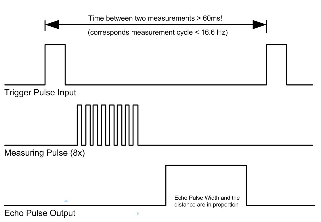
So, let's try to order the sensor to send a probing ultrasonic pulse, and then fix its return. Let's see how the timing diagram of the HC-SR04 looks like. The diagram shows that to start the measurement, we need to generate on the output trig a positive pulse with a length of 10 μs. Following this, the sensor will issue a series of 8 pulses and raise the level at the output echo, while switching to the reflected signal standby mode. Once the rangefinder senses that the sound has returned, it will complete the positive pulse on echo. It turns out that we need to do only two things: create an impulse on Trig to start measuring, and measure the length of the impulse on Echo, in order to then calculate the distance using a simple formula. We do. int echoPin = 2; inttrigpin = 3; void setup() ( Serial.begin(9600); pinMode(trigPin, OUTPUT); pinMode(echoPin, INPUT); ) void loop() ( int duration, cm; digitalWrite(trigPin, LOW); delayMicroseconds(2); digitalWrite (trigPin, HIGH); delayMicroseconds(10); digitalWrite(trigPin, LOW); duration = pulseIn(echoPin, HIGH); cm = duration / 58; Serial.print(cm); Serial.println(" cm"); delay (100); ) Function pulseIn measures the length of the positive pulse on the echoPin leg in microseconds. In the program, we record the flight time of the sound in the variable duration. As we found out earlier, we need to multiply the time by the speed of sound: s = duration * v = duration * 340 m/s We translate the speed of sound from m/s to cm/µs: s = duration * 0.034 m/µs For convenience, we convert the decimal fraction to an ordinary one: s = duration * 1/29 = duration / 29 And now let's remember that the sound traveled two desired distances: to the target and back. Let's divide everything by 2: s = duration / 58 Now we know where the number 58 came from in the program! We load the program on Arduino Uno and open the monitor of the serial port. Now let's try to point the sensor at different objects and look at the calculated distance on the monitor.
 Tasks
Now that we know how to calculate distance with a rangefinder, let's make some useful devices.- Construction rangefinder. The program measures the distance every 100ms using a range finder and displays the result on a character LCD display. For convenience, the resulting device can be placed in a small case and powered by batteries.
- Ultrasonic cane. Let's write a program that will "beep" with a buzzer at different frequencies, depending on the measured distance. For example, if the distance to the obstacle is more than three meters, the buzzer emits a sound once every half a second. At a distance of 1 meter - once every 100ms. Less than 10cm - beeps constantly.
Conclusion
The ultrasonic rangefinder is an easy-to-use, cheap and accurate sensor that performs well on thousands of robots. As we found out from the lesson, the sensor has disadvantages that should be considered when building a robot. A good solution would be to use an ultrasonic rangefinder paired with a laser rangefinder. In this case, they will offset each other's shortcomings.In this article, we will consider the principle of operation of the HC-SR04 ultrasonic rangefinder.
The principle of operation of an ultrasonic rangefinder is based on the emission of ultrasound and its reflection from objects in front. Based on the return time of the sound, using a simple formula, you can calculate the distance to the object. Rangefinder HC-SR04 is the cheapest rangefinder for hobby use. At a low price, it has good characteristics, it is able to measure distances in the range from 2 to 450 cm.

Components used (buy from China):
The principle of operation of the sensor can be divided into 4 stages:
1. We apply a pulse with a duration of 10 μs to the Trig output.
2. Inside the rangefinder, the input pulse is converted into 8 pulses at a frequency of 40 kHz and sent forward through the "T eye"
3. Having reached the obstacle, the sent impulses are reflected and received by the "R eye". We get the output signal on the Echo pin.
4. Directly on the side of the controller, we translate the received signal into a distance according to the formula:
pulse width (µs) / 58= distance (cm)
pulse width (µs) / 148= distance (inch)

Connecting to Arduino
The module is equipped with a four-pin 2.54mm connector
VCC: "+" power
TRIG(T): input signal output
ECHO(R): Output signal output (The length of the signal depends on the distance of the object from the sensor)
GND: "-" power
Having connected the sensor to the Arduino, all that remains is to fill in the sketch for work. In the sketch below, information about the distance will be sent to the computer port, and at a distance of less than 30 centimeters, turn on the LED connected to pin 13.
code example:
#define Trig 9 #define Echo 8 #define ledPin 13 void setup // initiate as exit pinMode(Echo, INPUT); //initiate as input pinMode(ledPin, OUTPUT); Serial.begin(9600); /* set the communication speed. In our case with a computer */) unsigned int impulseTime=0; unsigned int distance_sm=0; void loop() (digitalWrite(Trig, HIGH); /* We give a pulse to the trig input of the rangefinder */ delayMicroseconds(10); // equal to 10 microseconds digitalWrite(Trig, LOW); // Disable impulseTime=pulseIn (Echo, HIGH ); // Measure the pulse length distance_sm=impulseTime/58; Serial.println(distance_sm); // Output to the port if (distance_sm<30) // If the distance is less than 30 centimeters(digitalWrite(ledPin, HIGH); // LED on) else ( digitalWrite (ledPin, LOW ); // not lit otherwise ) delay (100); /* wait 0.1 seconds, The next pulse can only be emitted after the echo from the previous one has disappeared. This time is called the cycle period. The recommended period between pulses should be at least 50 ms. */ }Additional working example:
Interaction between rangefinder and servo. The distance measured by the rangefinder is converted into the angle of rotation of the servo
Program code example
//Tested on Arduino IDE 1.0.1#include
Arduino ultrasonic distance sensors are in great demand in robotics projects due to their relative simplicity, sufficient accuracy and availability. They can be used as devices to help avoid obstacles, get the size of objects, simulate a map of the room and signal the approach or removal of objects. One of the common options for such a device is a distance sensor, which includes an ultrasonic range finder HC SR04. In this article, we will get acquainted with the principle of operation of the distance sensor, consider several options for connecting to Arduino boards, an interaction diagram and examples of sketches.
The ability of an ultrasonic sensor to determine the distance to an object is based on the principle of sonar - by sending a beam of ultrasound, and receiving its reflection with a delay, the device determines the presence of objects and the distance to them. The ultrasonic signals generated by the receiver, reflected from the obstacle, return to it after a certain period of time. It is this time interval that becomes a characteristic that helps determine the distance to the object.
Attention! Since the principle of operation is based on ultrasound, such a sensor is not suitable for determining the distance to sound-absorbing objects. Objects with a flat, smooth surface are optimal for measurement.
Description of the HC SR04 sensor
The Arduino distance sensor is a non-contact type device, and provides high-precision measurement and stability. The range of its measurement range is from 2 to 400 cm. Its operation is not significantly affected by electromagnetic radiation and solar energy. The module kit with HC SR04 arduino also includes a receiver and a transmitter.
Ultrasonic range finder HC SR04 has the following technical parameters:
- Supply voltage 5V;
- The operating parameter of the power of the current is 15 mA;
- Passive Current< 2 мА;
- Viewing angle – 15°;
- Touch resolution - 0.3 cm;
- Measuring angle – 30°;
- Pulse width - 10 -6 s.

The sensor is equipped with four leads (standard 2.54 mm):
- Positive type power contact - + 5V;
- Trig (Т) – input signal output;
- Echo (R) - output signal output;
- GND - output "Earth".
Where to buy the SR04 module for Arduino
The distance sensor is a fairly common component and can be easily found in online stores. The cheapest options (from 40-60 rubles apiece), traditionally on the well-known site.
  Distance sensor module HC-SR04 for Arduino Distance sensor module HC-SR04 for Arduino
|  Another option for ultrasonic sensor HC-SR04 from a reliable supplier Another option for ultrasonic sensor HC-SR04 from a reliable supplier
|
 Distance sensors SR05 Ultrasonic HC-SR05 (improved performance) Distance sensors SR05 Ultrasonic HC-SR05 (improved performance)
|  HC-SR05 HY-SRF05 module for UNO R3 MEGA2560 DUE from a reliable supplier HC-SR05 HY-SRF05 module for UNO R3 MEGA2560 DUE from a reliable supplier
|
Scheme of interaction with Arduino
To obtain data, you must perform the following sequence of actions:
- Apply a 10 microsecond pulse to the Trig output;
- In the hc sr04 ultrasonic rangefinder connected to the arduino, the signal will be converted into 8 pulses with a frequency of 40 kHz, which will be sent forward through the emitter;
- When the impulses reach the obstacle, they will be reflected from it and will be received by the receiver R, which will provide an input signal at the Echo output;
- On the controller side, the received signal should be converted into a distance using formulas.
Dividing the pulse width by 58.2 gives the data in centimeters, dividing by 148 gives the data in inches.
Connecting HC SR04 to Arduino
Connecting an ultrasonic distance sensor to the Arduino board is quite simple. The connection diagram is shown in the figure.

The ground pin is connected to the GND pin on the Arduino board, the power output is connected to 5V. We connect Trig and Echo outputs to arduino to digital pins. Breadboard connection option:

Library for working with HC SR04
To facilitate work with the HC SR04 distance sensor on arduino, you can use the NewPing library. It has no problems with pings and adds some new features.
The features of the library include:
- Ability to work with various ultrasonic sensors;
- Can work with a distance sensor with just one pin;
- No lag of 1 second in the absence of echo ping;
- For simple error correction, there is a built-in digital filter;
- The most accurate distance calculation.
You can download the NewPing library
Distance measurement accuracy with HC SR04 sensor
The accuracy of the sensor depends on several factors:
- air temperature and humidity;
- distance to the object;
- location relative to the sensor (according to the radiation diagram);
- performance quality of the elements of the sensor module.
The principle of operation of any ultrasonic sensor is based on the phenomenon of reflection of acoustic waves propagating in the air. But as is known from the course of physics, the speed of sound propagation in air depends on the properties of this very air (primarily on temperature). The sensor, emitting waves and measuring the time until their return, does not guess in which medium they will propagate and takes some average value for calculations. In real conditions, due to the air temperature factor, the HC-SR04 may have an error of 1 to 3-5 cm.
The factor of distance to the object is important, because the probability of reflection from neighboring objects increases, in addition, the signal itself attenuates with distance.
Also, to improve accuracy, it is necessary to correctly direct the sensor: make sure that the object is within the cone of the radiation pattern. Simply put, the HC-SR04's "eyes" should look straight at the subject. 
To reduce errors and measurement errors, the following actions are usually performed:
- the values are averaged (we measure several times, remove bursts, then find the average);
- using sensors (for example,) the temperature is determined and correction factors are introduced;
- the sensor is mounted on a servomotor, with the help of which we “turn our head”, moving the radiation pattern to the left or right.
Distance sensor examples
Let's look at an example of a simple project with an Arduino Uno board and an HC SR04 distance sensor. In the sketch, we will get the value of the distance to objects and output them to the port monitor in the Arduino IDE. You can easily change the sketch and the connection scheme so that the sensor signals the approach or distance of an object.
Connecting the sensor to arduino
When writing the sketch, the following pinout option for connecting the sensor was used:
- VCC: +5V
- Trig - 12 pins
- Echo - 11 pins
- Ground (GND) – Ground (GND)
Sketch example
Let's start working with the sensor right away with a relatively complex option - without using external libraries.
In this sketch, we perform the following sequence of actions:
- With a short pulse (2-5 microseconds), we transfer the distance sensor to the echolocation mode, in which ultrasonic waves with a frequency of 40 kHz are sent into the surrounding space.
- We are waiting for the sensor to analyze the reflected signals and determine the distance by the delay.
- We get the value of the distance. To do this, we wait until the HC SR04 generates a pulse proportional to the distance at the ECHO input. We determine the duration of the pulse using the pulseIn function, which will return us the time elapsed before the signal level changed (in our case, until the reverse edge of the pulse appeared).
- Having received the time, we convert it into a distance in centimeters by dividing the value by a constant (for the SR04 sensor, this is 29.1 for the “there” signal, the same for the “back” signal, which will give a total of 58.2).
If the distance sensor does not read the signal, then the output signal conversion will never take the value of a short pulse - LOW. Since for some sensors the delay time varies depending on the manufacturer, it is recommended to set its value manually when using these sketches (we do this at the beginning of the cycle).
If the distance is more than 3 meters, at which the HC SR04 starts to work poorly, it is better to set the delay time to more than 20 ms, i.e. 25 or 30 ms.
#define PIN_TRIG 12 #define PIN_ECHO 11 long duration, cm; void setup() ( // Initialize communication on the serial port Serial.begin (9600); // Define inputs and outputs pinMode(PIN_TRIG, OUTPUT); pinMode(PIN_ECHO, INPUT); ) void loop() ( // First generate a short pulse duration 2-5 microseconds digitalWrite(PIN_TRIG, LOW); delayMicroseconds(5); digitalWrite(PIN_TRIG, HIGH); // Setting the signal high, wait about 10 microseconds. At this point, the sensor will send signals at a frequency of 40 kHz. delayMicroseconds(10); digitalWrite(PIN_TRIG, LOW); // Delay time for the acoustic signal on the sonar duration = pulseIn(PIN_ECHO, HIGH); // Now it remains to convert time to distance cm = (duration / 2) / 29.1; Serial. print("Distance to object: "); Serial.print(cm); Serial.println(" see."); // Delay between measurements for the sketch to work correctly delay(250); )
Sketch using the NewPing library
Now let's look at a sketch using the NewPing library. The code will be significantly simplified, because all the actions described earlier are hidden inside the library. All we need to do is create an object of the NewPing class, specifying the pins with which we connect the distance sensor and use the methods of the object. In our example, we need to use ping_cm() to get the distance in centimeters.
#include
An example of connecting an ultrasonic rangefinder HC SR04 with one pin
Connecting the HC-SR04 to the Arduino can be done using a single pin. This option is useful if you are working on a large project and you do not have enough free pins. To connect, you just need to install a 2.2K resistor between the TRIG and ECHO pins and connect the TRIG pin to the arduino.
#include
Brief conclusions
Ultrasonic distance sensors are versatile and accurate enough to be used for most hobby projects. The article discusses the extremely popular HC SR04 sensor, which is easily connected to the arduino board (for this, two free pins should be immediately provided, but there is also a connection option with one pin). There are several free libraries for working with the sensor (only one of them, NewPing, is considered in the article), but you can do without them - the algorithm for interacting with the sensor's internal controller is quite simple, we have shown it in this article.
Based on my own experience, the HC-SR04 sensor is accurate to within one centimeter at distances from 10 cm to 2 m. At shorter and longer distances, strong interference may occur, which greatly depends on the surrounding objects and how you use it. But for the most part, the HC-SR04 did the job just fine.