Police stroboscope from available parts. Automotive strobe light simple circuit for DIY assembly Police strobe light circuit board layout
The interest of the modern motorist is not limited to attention to the car as a means of transportation. In many respects, the effect and impression that can be made on all participants in the movement is important. After a widespread ban on imitators of flashing lights of law enforcement officers and official cars, somehow unexpectedly, the fashion for a stroboscope on the grill and a double signal began to gain momentum.
Most of the above schemes are not designed to completely imitate the signals of official cars, it is rather a purely sporting interest. And to whom and for what to pay fines, everyone decides for himself, based on his capabilities.
There are several simple ways to organize a stroboscope on a car, it all depends on the amount of effort and money that can be spent to build a car stroboscope. Most often, they try to get the most realistic flickering of strobe lamps.
Several simple schemes of LED strobe lights for cars have been tested in practice:
- according to the simplest scheme using two relays 494.3787;
- based on the 555 timer and the k561ie8 circuit;
- on the PIC12F675 microcontroller;
- on the element base transistors 315 series.
Note! The safest and most popular way is to use a flashing effect by installing LEDs in your car headlights. It's beautiful and stylish.
We assemble a car stroboscope with our own hands
The easiest way to build a reliable circuit on a car is to use a couple of relays from the gazelle turn signal system, a starter relay and a couple of trimming resistors. It is easy to assemble such a stroboscope circuit with your own hands, and even special knowledge or skills are not required.

The specified scheme provides for the connection to the daytime running lights of the car. If desired, you can switch the connected daytime running lights or strobe flashers. The advantage of this approach is the absence of overload-sensitive electronic components in the circuit. The relays, even in the event of an overload of the electrical circuit, in most cases will remain intact, although they can lead to blown fuses.
To build a strobe circuit, the following is required.
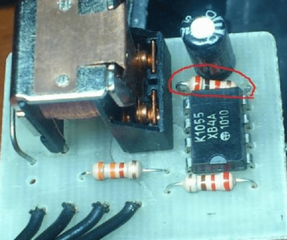
- First, we disassemble the case of the turn relay and carefully remove the white constant resistor with numerous transverse colored stripes.
- In a variable resistance of 20-25 kOhm, we solder the middle electrode to one of the side ones.
- We solder the variable resistance instead of the removed element in such a way that, after reassembly, the rotary stem of the variable resistor could be freely rotated.
- We assemble the circuit, we carry out a similar procedure with the second relay.
- We assemble the circuit shown in the figure, and after applying the supply voltage by turning the control rods, we select and synchronize the flashing frequency of the strobe lights on the car.
If you use a variable resistance of 450 kOhm, the blinking frequency will be much less, but for a more accurate selection of the blinking frequency, you can select several different resistances and achieve the desired frequency.

Building a circuit based on a microprocessor
The most “advanced” motorists in the basics of microelectronics believe that the controller-based stroboscope circuit will be the most effective. On the PIC12F675 microcontroller, the circuit will be able to provide current pulses up to one ampere with adjustable duration.
The stroboscope circuit for a car is easy to assemble with your own hands. As a load, a package of light elements is most often used, with the ability to change the flicker frequency of the stroboscope on LEDs. The processor itself controls two powerful KT817 transistors and can produce seven different combinations of signals. The system itself is quite common in industrial circuits for service flashers, especially for simple strobe systems on a car radiator grille.
The most unpleasant thing in connecting such circuits is the high sensitivity of any microprocessors to overvoltage or the occurrence of a short circuit mode. Therefore, when assembling and soldering, it is imperative to use a good ground. In addition, the use of a stabilized power supply is mandatory; usually, a circuit on a paired low-voltage zener diode is used for these purposes.
When connecting the stroboscope circuit to the car's electrical wiring circuit, it is necessary to first completely disconnect the power from the battery, it is strictly forbidden to start and test the circuit in the absence of load.
Do-it-yourself police stroboscope on a logic counter
To obtain an effect similar to the flickering of LEDs in a strobe on law enforcement service motors, you can use an interesting option on the 561 series logic counter and 555 timer. The circuit turns out to be somewhat more complicated than previous developments, but if you have a couple of hours of free time and the ability to solder, you can assemble a small homemade product on a printed circuit board.
Packages of LEDs with a total current consumption of not more than 3A are used as a load; if desired, they can be replaced with low-power halogen lamps with a total power consumption of up to 30 W.
The specificity of constructing such a stroboscope circuit on LEDs is an interesting feature of the formation of a control signal. The microcircuit on the 555 assembly acts as a source of a control signal input to the counter. Without going into the specifics of the operation of the stroboscope, we can only note that the scheme for igniting and extinguishing the LEDs is copied from the stroboscope of a police car.
Rectangular pulses are fed to the counter and summed up. After a certain programmable time, the potential on the control contact changes from high to low.
The stroboscope works like this: each of the LED packages flashes, gives a certain programmed number of flashes and goes out, then the signal is transmitted to the next LED package and so on in a cyclic mode.
Important! Powerful KT819 or bipolar KT818 are used as control keys in the stroboscope circuit, which allows you to control high currents in the load.
To power the 555 microcircuit, the maximum supply voltage cannot be increased more than 18 volts, the stabilizer is not designed for a larger operating range, and the circuit remains operational even when the voltage drops to 5 V.

How to make a stroboscope with your own hands on simple spare parts
The most budgetary way to build a do-it-yourself LED stroboscope is not to buy a bunch of spare parts on the radio market for a couple of thousand, but to try to use old Soviet or Chinese spare parts.
We use mikruha 155 series as a signal source, AG1 can be used. After power is applied, the microcircuit sets a positive potential on the control pin, and as the capacitor charges, the potential drops and opens the control signal to the KT315. The capacitance of the capacitor determines the length of the flash, at 0.1 uF it will be approximately 0.01 sec, which is quite enough to obtain the desired optical effect.
On the 6th leg 155 of the microassembly, a series of pulses will be generated, coupled with the pulses of the ignition system. They fall on the control electrodes of two KT 829 transistors. Then the transistor opens, and a significant current will flow through the load from the LEDs.
If the stroboscope circuit consumes more than 60 watts, use standard aluminum radiators to cool the transistors.
The result, or the design of strobe LEDs for cars
For most fans of homemade strobe lights, it is sometimes more important to hide the fact of owning homemade light illumination, similar to a police one. Therefore, often the package of light bulbs or LEDs is made removable so that it can be easily installed on the hood or roof of a car. Sometimes, for greater disguise, an easily removable plastic cover is put on top of such a block, in appearance it strongly resembles a taxi lantern.
The advantage of this design solution is that the stroboscope fixture is easy to remove and even throw away. A stroboscope with a plastic cover on top will resemble a taxi driver's lantern and will not attract the attention of the police in the parking lot or when the car accidentally stops on the road.

The second installation option is to install a package of strobe LEDs in the area of \u200b\u200bthe radiator grille of a car or in the cavity of a headlight lamp. This is a more expensive and effective way, as it will require some alteration of the car's optics, and in the event of a conflict with law enforcement officers, it can become the basis for placing the car in a car impound.
A very powerful LED strobe that will perfectly complement any disco dance floor. A stroboscope was built on three LED matrices with a total power of 150 watts.
The principle of operation of the device is to give very short pulses of light (flashes) after a given period of time. In action, it very much resembles lightning during rain, when a completely dark room illuminates a bright light for milliseconds.
During the disco, it looks especially bewitching.
Details:
- LED Matrix -
- 12 V source -
- Transistor K2543 -
- Diode bridge -
- Chip NE555 -
- Resistors and Capacitors -

Strobe circuit

I would not say that the scheme is complex, rather simple. But it does not have galvanic voltage isolation, which means that you cannot touch any of the circuit elements during its operation and be especially careful during assembly.
Visually, the circuit can be divided into a 12 V power supply, a pulse generator, a rectifier and a line of LEDs.
Strobe operation
A short pulse generator is assembled on the NE555 chip. The time between pulses can be changed by turning the knob of the variable resistor R3.A field-effect transistor switch is connected to the output of this generator, which switches a voltage of 220 V in the power supply circuit of LED matrices connected in parallel to each other.
LED matrices are powered by direct current, which is rectified by a diode bridge. This is necessary in order to be able to switch the circuit with a field-effect transistor, which only works with constant voltage.

Strobe assembly
The stroboscope is assembled in a casing from the cable channel. The LEDs are bolted to the wide side, no heatsinks. Since the LED is used somewhere at 2-5% of its power (pulse work), there is no need for heat sinks.
The side walls are cut out of the same cable channel and glued with glue. Above is a variable resistor to adjust the flicker frequency.

Blocks of the circuit in the case:


Warning
LEDs are very powerful and can damage your eyes, so looking at them while working is not recommended. Strobe flashes are especially dangerous, as the eye relaxes in the dark, and a bright pulse penetrates directly into the retina.Also, do not forget that the entire circuit is under mains voltage, which is life-threatening.
The result of the work
The work of the stroboscope, unfortunately, cannot be conveyed either through a photo or through a video. Since even a video camera captures a short impulse very poorly, and as a result, it simply lights up.But I can say from myself that the strobe turned out to be excellent, the flashes are short and very bright. It looks very impressive, in general, everything is as it should be.

On the Internet for a very long time I tried to find a circuit for an LED stroboscope. People who understand electronics will now say "just think, a stroboscope, and what's so complicated about it." Stroboscopes are different, and all previously known schemes did not suit me, since the only goal was to get the effect of a police strobe. Maybe not everyone noticed, but the police flasher works in a very interesting way - each light flashes several times, then switches. As a result, we get the effect, which is better known as the "police flasher".
The stroboscope can be assembled on different schemes using a multivibrator, but none of them provides the desired effect or the effect is not stable. Such a task is quite feasible if you know how to flash MK, but in my case it was not possible (unfriendly to microcontrollers). It remained to find an alternative based on simple and accessible elements. A very interesting electrical circuit was found on foreign sites using the 555 series timer. The microcircuit works as a square wave generator.
The circuit also uses the K561IE8 counter (in my case, an imported analogue was used, in general it is not critical). The microcircuit is a decimal divider counter, that is, it has 10 decoded outputs. It consists of high-speed counters and decoders. The work of the counter, I think, is clear to everyone, I will not explain. In order to get the flasher effect, where each LED blinks twice, you need to use two close outputs of the counter. When a signal is applied to the counter, pulses are generated alternately at the outputs. First, an impulse is formed at the first output, then it switches to the second, third, and so on until the end, then the process repeats from the beginning. The frequency and intensity of flashes can be adjusted if it is regulated by the value of the resistor between 6 and 7 pins of the timer. In the output stage, you can use almost any powerful reverse conduction transistors, in my version 13007 were used (soldered from the LDS ballast board).

You can also set the number of flashes per lamp (1-5 flashes before switching). To do this, simply add diodes to the outputs of the microcircuit. For example, one channel is pins 4 and 2, and the second is 7 and 9, respectively, for a triple flash one channel, you just need to connect pins 1,3,5 (first channel) and 6,8,0 (second channel) with diodes to each other friend. The power of the connected load depends on the power switches. If a low-power LED stroboscope is planned, then low-power KT315 can be used at the output, with more powerful loads, field-effect transistors should be used as output keys.

The device has a fairly wide range of input voltages, it starts to work from 4.5-5 volts, while the flash frequency does not change depending on the input voltage rating. Such a stroboscope cost only $ 1.5 (transistors were available). You can also exclude a 5-volt voltage regulator from the circuit; the microcircuit works great from a car battery. If you plan to use LEDs, then do not forget about the limiting resistors, otherwise you will observe the clouding of the LED crystal.

The entire installation was made in an aluminum case from a Chinese electronic transformer for powering 12 volt halogens.

The box turned out to be very suitable. The device is indistinguishable from the factory one, although the components were assembled on a breadboard.
A stroboscope is a very familiar device that has found wide application in many branches of science and technology. A simple example of a strobe light is police flashers. Such flashing lights are considered a special signal and their use is illegal. But despite this, some adventurers who seek adventure on their own are accustomed to using the illegal to distinguish themselves from others. To be honest, I consider myself one of them, so I decided to make a "MENTOVSKAYA" stroboscope with my own hands and share the circuit with you.
LED stroboscope circuit
Of all the schemes that can be found on the Internet, this the simplest and most fully working. Let me remind you that such a stroboscope differs from a simple flasher in that here you can set the flashing frequency and the number of LED blinks. Simply put, each LED flashes 2 , 3 (up to 4 times is possible) then switches and the second LED starts flashing. It turns out a complete analogue of police strobe lights, which are best used in the remote surroundings of your area, otherwise you face a round fine for using a special signal.

The stroboscope circuit does not contain MK. The master oscillator is everyone's favorite timer 555. The CD4017 counter has a domestic counterpart (K561IE8). This is a decimal divider counter with 10 decoded outputs.
The signal from the outputs of the microcircuit is amplified by transistor switches, there is a very large choice. If you are going to connect LEDs, then you can exclude transistors altogether, to power more powerful LEDs or LED assemblies, you can use any low-frequency bipolar transistors - KT819/805/805/829, etc.

More powerful lamps can be connected to the strobe, for example, halogen lamps from car headlights with a power of 100 or more watts. To do this, you only need to use powerful field switches IRFZ44, IRF3205, IRL3705, IRF1405 and other N-channel power transistors of the appropriate power.
The stroboscope was mounted in a housing from an electronic transformer, the housing simultaneously serves as a heat sink for transistors, although overheating is not observed on them.

Such a home-made stroboscope can work for hours, the circuit does not need additional adjustment and works immediately after switching on. The device is powered by the car's on-board network of 12 volts, although it starts working from 6 volts.
Video of the work of a homemade strobe: