Different ways of joining wood. Simple ways to connect wooden parts. Fastening elements made of wood - useful recommendations wood. Methods and ways of joining wooden parts Methods of joining wooden frames
Connecting wooden parts - connection methods
A mustache is called a beveled straight or stepped cut of the ends of the bars. For the simplest, direct connection to the mustache, the ends of the bars are marked at an acute angle of about 15; with a fine-toothed saw, bevels are cut with an allowance of 2–3 mm for processing (Fig. 73, a). Bevels are first planed with a planer, then they are processed with a grinder or jointer. To protect the thin ends of the bar from deflection and chipping, they are planed on a lining (Fig. 73, b). Applying the bevels of the bars one to the other, check them for clearance, paying attention to the fact that the axes of the bars are strictly parallel.
After precise fitting, the bevels are lubricated with glue and pressed in with clamps with spacers over the entire width of the bars or clamped in the zvinka. When splicing thin rails, the joints after gluing are tightly wrapped with strong threads and coated with glue again on top (Fig. 73. c). This connection method refers to the angular knitting of the bars. At both ends of the joined bars, after marking with a thickness gauge, identical ledges are cut out with a saw or chisel up to half the thickness of the bar (Fig. 73, d).
An incision with a saw along the markup is first made along the bar, and then across. For greater joint density, a longitudinal section is made on one bar outside the marking risk, and on the other inside it; a transverse incision is made with a slight inclination inward. By the method of joining a half-tree, in addition to angular knitting, it is possible to produce tee knitting of bars (it is also called middle, T-shaped, transverse). With tee knitting, the end of one bar is fixed in an overlay in the middle of the other, having hollowed out the corresponding straight or trapezoidal recess in it according to the marking with a chisel (Fig. 73, e. f. g). When connecting to the overlay in half a tree for greater strength; gluing and additional fastening with nails, screws, overlays or dowels is carried out. Nagels are wooden cylindrical or conical studs driven with glue into holes previously obtained with an awl, drill or gimlet on the parts to be joined. The ends of the dowels protruding beyond the plane of the product are cut off with a chisel. The connection of the part on spikes (studded knitting) has even greater strength and is widely used for corner and tee joints of bars. In spike knitting, the parts to be joined have one or more spikes and their corresponding sockets and eyes. Spikes, nests, eyes and their elements are shown in Figure 74. Nests can be blind if they are open only on one side, or through, if the hole passes through the bar and is open on both opposite sides. Spikes are single, double, triple; lugs are made in strict accordance with them. By design, the spikes can be integral with the bar, being its continuation, or can be made separately. The latter are called insert spikes. In shape, the spikes are straight (rectangular), cylindrical (plug-in), cut-in in the form of a dovetail, etc. The spikes, nests and eyes must be made very accurately and enter into the parts to be joined without a gap as tightly as possible. The presence of gaps between the spikes and the walls of the nest weakens the knitting and makes it fragile. With inaccurate manufacture of spikes, in the event of a thickened spike, when it is wedged into the socket, splitting may occur. The connection with a direct spike is the simplest and at the same time provides sufficient strength for the product. To carry out knitting with a straight spike on one kosh bar, using a saw and a chisel, one or more rectangular protrusions are cut out according to the marking - spikes, which I make through or semi-hidden (Fig. 75, a, b, c). When connecting the bars on one spike, its thickness is taken equal to 1/3 - 1/5 of the thickness of the bar, and when knitting into two spikes, their thickness is taken equal to the thickness of the cheeks. On another mating bar, exactly the size of the spike, mark and gouge out the corresponding recess - the socket. The depth of the blind socket is made more than the length of the spike by at least 2 mm; this is done so that in case of possible shrinkage of the bar, a gap cannot form between the shoulders of the spike and the edges of the socket. The thickness of the spike is taken not less than 1/3 of the thickness of the spike bar. The length of the blind spike is taken equal to approximately 2/3 of the thickness of the bar in which the nest is selected. At the stud entering the socket, one or two end ribs are chamfered at an angle of 30 °, which facilitates the insertion of the stud into the socket. Types of various more complex joints of bars and boards with angular viscous are shown in Figure 76. Sufficiently strong angular viscous bars, used for collapsible joints, are made on plug-in cylindrical or rectangular dowels - dowels, with a diameter of 5 to 12 mm, depending on the thickness of the bars. When making the connection requires very precise trimming of the bars and precise drilling of nests for plug-in spikes (Fig. 76, g, h). Somewhat more difficult is the angular knitting of boards and shields (at the corner) or the so-called box knitting. The connection can: be carried out with spikes - through, half-hidden and sunken (Fig. 77). The width of the spikes is taken equal to 0.6 - 0.8 of the wall thickness and the bevel angle of the spikes is 15°. The tee or T-shaped connection of the bars is used in the manufacture of cabinet shelves, tables, chairs and other joinery and is performed with a single or double spike into a through or blind hole. The tee connection is carried out as a detachable connection (performed on wedges) and one-piece (thorn). .78). Rallying is used in the manufacture of products of considerable width - shields, drawing boards, etc. (carried out with mandatory subsequent gluing. Examples of connecting wood elements by rallying are shown in Figure 79). The basic rules for pairing wood elements and knitting individual blanks are as follows. Blanks, individual elements and parts made of wood, intended for connection, are carefully prepared in advance. They must have the correct dimensions, and their sides must be parallel to each other. It is impossible to correct incorrect workpieces during the knitting process. Paired parts of the parts to be joined (same in purpose) must have the same dimensions and be interchangeable. After preparing and aligning the workpieces to be joined, determining their working surfaces and the connection order, marking is carried out. Paired mating blanks are marked on a pole. The marking of boards and shields starts from the edges, transferring the marking lines further to the plate and to the second edges. The marking is transferred from one side of the workpiece to the other by turning the workpiece in one direction (for example, towards itself). When knitting frames, the markings of the eyes are made double-sided. When studded knitting, the markings are carried out along the nest, taking into account the dimensions of the existing bits. The marking of the eyes is done by the spike; sawing the spikes is done with a wide, fine-toothed saw, from the front side of the spike (Fig. 80). The drawing of parallel lines during marking is carried out by a thickness gauge in turn on all prepared blanks, in compliance with the specified dimensions. The drawing is carried out from the same front or inner sides, taken as the base. To prevent splitting of wood and ensure the straightness of the lugs during transverse marking of the spikes, it is recommended to cut the marking lines passing through the lugs and shoulders with the angle of a sharp chisel before sawing or chiselling. When sawing spikes and eyes, the saw is directed in such a way that the cut goes next to the intended marking line, without touching it. When sawing the spikes, the saw is directed along the marked risk from its outer side, and when sawing the eyes, from the inside. Before gluing, the prepared parts and blanks are pre-assembled in a clamping fixture and distortions and various defects are eliminated. For greater strength, mainly when knitting products with through sockets, it is recommended to wedge the spikes; wooden wedges are put on glue. When assembling blanks and individual parts of wood into a whole product, mallets or hammers should be used, striking through softwood pads (Fig. 81). The most common ways of permanent connection of wood are the connection of parts with a mustache, the connection to the floor of a tree, knitting on studs, and others, and in all these cases, the strength of the connection is acquired only after gluing the parts to be joined.
glue
When using glue, remember:
- the surfaces to be glued must be well adjusted to each other;
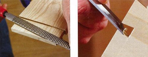
- for better bonding, the parts should be treated with a rasp, that is, roughened;
- parts to be glued must be made of well-dried wood;
- surfaces to be bonded must be clean and free of grease;
- the glue is applied evenly, not too thin (for this you can use the old blade of a hacksaw for metal);
- when gluing, the parts must be well compressed and secured with clamps, wedge clamps, etc.
Simple ways to connect wooden parts
Wooden parts can be connected in many ways. The simplest method is a butt joint, and the most difficult can be considered a dovetail joint. There are ways to connect wood, differing in complexity and strength.
The choice of connection type depends on what we are manufacturing. For example, when assembling cabinets, butt, seam joints and joints in a groove and mustache are used. More often, in the manufacture of door frames, a spike-to-socket connection is used.
1. Butt joint. In a butt joint, the edges of the material are connected using glue and other fasteners.
Advantage - easy execution.
The disadvantage is the low strength of the connection.
This type of connection is used where strength is not so important - front frames or decorative inserts. Such connections can be strengthened with dowels, lamellas or special screws.
2. Connection in the mustache. A mustache joint is a butt joint, only the ends are beveled at an angle of 45 degrees. The mustache connection also needs to be strengthened with fasteners.
3. Groove and seam joints. The joints in the grooves are longitudinal and transverse, and they differ in the direction of the groove in relation to the direction of the wood fibers.
groove connection
Seam joints are characterized by a rectangular ledge on the edge of the board.
Advantages of connection in grooves and seam connections - high strength of the connection.
The disadvantage is that it is more difficult to manufacture than butt joints.
In the manufacture of furniture, these methods of joining wood are mainly used. Each connection method will be discussed in more detail in the following articles.
Fastening wood elements with special metal plates will not only facilitate the carpenter's work, but also provide a reliable and durable connection. When using this method of connection, the elements of wood structures are not weakened at the junctions by notches and spikes, this allows the use of material with small cross sections under the same loads.
The use of metal overlays makes it possible to reduce costs compared to traditional designs. Linings are made of stainless steel or stainless steel can be replaced with galvanized iron. Such pads are applicable for both external and internal structures. If someone does not like the shine of the metal, they can be covered (in particular, when decorating the interior) with paint or colored varnish.
Linings and other details for connecting wooden elements are fixed with special twisted nails or screws (self-tapping screws). To ensure the design strength of the joints, it is necessary to determine the required number of nails for each overlay. If you have experience, then you can be guided by your own intuition.
If necessary, such overlays can be cut out or cut out of strip or sheet steel with a thickness of 2-4 mm. Holes for screws and nails must be countersinked so that the head of the nail or screw goes deep into the hole flush with the surface of the lining. 
Flat pads for connecting wooden elements are used for both light and more powerful structures. The pads are fixed either only with nails, or with nails and screws.
How to fix wooden elements
Corner (angle up to 135°) linings are designed to make connections that take heavy loads (for example, roof trusses or cantilever beams of a frame structure). Overlays let out with various width and length of the parties.
Corner fixings of wooden elements
Corner console with punched corner reinforcement designed for attaching heavy beams to masonry. First, in the masonry (away from the seams), threaded studs are fixed on the dowels, then the corner console is screwed.
wooden elements. How to fix
There are also universal fittings with a slot on one side. By bending or unbending, they can be adjusted to any angle of the mating parts. They are mainly used to make connections subject to light loads.
Universal connectors
Nodal or crossbar connecting pad provides the perception of compressive and tensile loads. Their dimensions and angles of conjugation are different.
Carrier beam connection
So the carrier beam is connected to the corner console. Pay attention to the fact that a small gap is left between the wall and the beam to ventilate the end.
Ring connectors
Ring fittings prevent displacement of structural elements that do not perform a load-bearing function. The connecting parts are tightened with bolts.
Linings for connecting rafters with girders
Linings for connecting rafters with girders. Their location allows you to compensate for the wind loads acting on the roof. The patches can be of various sizes.
Knot scarf
This nodal gusset allows you to connect three structural elements at the same time. It is designed to withstand very large loads.
Universal connections
Universal connectors and beam anchors. Both of them are able to withstand high loads.
After reviewing this material and considering examples of joining with metal plates, it will be easier for you to make your choice of how to join wood elements.
There are many ways to connect elements and parts made of wood.
Basically, these are joints of wood parts along the fibers - splicing in width - rallying and at an angle - knitting. When repairing an apartment, joining parts of wood along the length is rarely used, due to the fact that all elements and parts of products can be made from solid lumber.
Rally is used when receiving shields. It is difficult to choose a wide board for a product, especially since a wide board warps and cracks over time. Wide shields are recruited from separate bars or boards, using a connection for a smooth fugue, in a quarter, in a rectangular groove and a comb, in a groove on a rail.
In addition to all kinds of spiked joints, the simplest connection is also used - hammering together with nails and studs. But the nail head on the front surface of the product significantly impairs its aesthetic appearance, so they are hidden in various ways. So, for example, the nail is not driven in completely, the head is bitten off, and then driven in with a deepening, covering it with putty. Sometimes the head of the nail is pre-riveted, and the nail is driven in so that the resulting narrow head coincides with the direction of the wood fibers. They deepen it with hammer blows through the head of another nail laid sideways, and the recess is puttied. 
There is another way in which, first, a layer of wood is cut with a chisel, a nail is hammered in, and wood chips are glued into place.
If, when connected with a nail, the latter passes through, the protruding end is folded into a hook and hammered flush. A stronger connection is a screw connection. In this case, it must be remembered that it is necessary to screw the screw into a specially prepared hole, which is made with a drill or an awl. The diameter of this hole should be slightly smaller than the diameter of the top of the screw. Sometimes, when screwing into hard wood, the screw must first be lubricated with soap, grease or other similar material.
All connections described earlier are made with the obligatory use of glue, and in some cases they are additionally reinforced with wooden dowels, dowels, screws, metal plates, squares.
Making tight joints from wood
Professional layout with precision tools
Tight joints of wood products start with neat and precise markings. This is especially important if you are making connections by hand and marking lines serve as guides for tools. The accuracy of machining depends on the accurate setting of stops, stops, overhang and inclination of saw blades and cutters. The steps below will help you achieve great results. This does not require unique equipment, but should choose tools that guarantee accuracy and efficiency. Also, get in the habit of observing the following rules when measuring and marking.
- Use precise tools. For example, try, if possible, to use an accurate steel ruler instead of a tape measure with a flexible tape in most cases. Good tools cost more, but they will last you a lifetime.
- Consistency is the key to success. Use the same measurement tools throughout your project to avoid small inaccuracies that affect the quality of your connections. For example, the 300 mm marks on the two rulers may not match.
- The main thing is the result, not the measurements. In most cases, measurements should be avoided when you can use an already finished part with connection elements to mark an adjacent part. For example, having made spikes on the front wall of the box, use them to mark the “dovetails” on the blanks of the side walls.
- Use the right markup techniques and the right tools. With good marking and measuring tools, it is easier to achieve the required accuracy.
|
It is not always possible to accurately align the end of the ruler with the end of the workpiece, so in such a situation it is better, as they say, to sacrifice zero. Align the next ordinal division with the end and mark the size in accordance with it. |
To draw a thin line parallel to the edge of the workpiece, use a thickness gauge. Shows the outline of the nest on the post after determining the position of the end of the crossbar |


The sharp knife leaves the thinnest line, providing high accuracy of a marking. In some cases, the recessed line also becomes the starting position for the chisel.
Fine-tuning of machines for precise machining of parts
Machine tools and power tools will only produce great results if they are properly set up and adjusted. This page shows the main features of setting up three machines that are essential for most workshops: a saw, a planer, and a router table. Having prepared them for work, remember the following rules.
- First of all, make blanks of the same thickness. Start any project by cutting all pieces to the same thickness. Any differences in thickness make it difficult to obtain accurate joints and necessitate additional adjustments in grinding and sanding.
- Reasonable approach. Long boards are inconvenient to process, so it is better to immediately cut them into blanks with a small allowance, which are easier to handle, achieving the necessary accuracy.
- Double check the dimensions. The actual thickness of plate and sheet materials, as a rule, differs from the nominal, so a caliper should be used to measure them. Only after that, cut the grooves, tongues and folds of the appropriate width.
Before cutting anything, check that the blade is parallel to the slots in the table, set the cross (corner) stop to 90°, and then set the rip fence parallel to the blade. When ripping, use a pressure comb to hold the workpiece firmly against the rip fence.

Align the rear table with the highest point of the cutting edge path of the knives as shown in the figure on the right. Then, using a checked square, make sure that the rip fence is set exactly at right angles to the back table. For best results, always press the workpiece against the fence when planing. Slowly feed the board onto the rotating cutter head. When the front end of the board passes over the knives, move the downforce forward so that the board is pressed against the back table. For best results, adjust the rear table and rip fence.

Plan to do most of your milling work in multiple passes by setting the fence to the final height or width for the last pass. Fix the position of the router after each change in the overhang of the cutter. When selecting grooves, tongues, folds and other elements of connections, use clamps similar to the clamping comb shown here. It is easy to do it yourself, it does not require a lot of material.

The final fit guarantees success
No matter how many connections you want to make on the machine, after each change in settings, always make test passes and connection samples using offcuts. Adjustment should be continued until a tight assembly of the test joint is achieved, and only then proceed to processing the details of the project. But despite all your efforts, sometimes you can find imperfections in the connections. Chips on the saw table or subtle warping of a previously planed workpiece can ruin the job and make assembly impossible. If the piece is too thick or too wide, resist the temptation to adjust the size with the help of lathes. Precise fitting is best left to hand tools.
- Little zenzubel. With its help, it is possible to quickly remove a layer with a thickness of 0.5 mm or more from a wide spike or comb. The low angle zener is especially effective when working across the fibers. The cutting edge protruding from the side allows you to process the inner corner close to the stud shoulder.
- Rasp or file. A flat rasp with a coarse cut quickly removes material, but leaves a rougher surface than a planer. A flat file is slower, but it works well for smoothing the surface.
- Sandpaper. If you need to remove very little material from a spike or other wide surface, glue a piece of 100 grit sandpaper to a suitable piece of board or cork block. Use self-adhesive sandpaper, or stick with regular sandpaper using spray adhesive or double-sided tape. This method allows you to process only one plane without affecting the adjacent ones, as happens if you just wrap the bar with sandpaper.
- Chisel. Blades of various widths will allow you to remove material from any hard-to-reach places. When scraping a flat surface, hold the chisel with the bevel up, pressing its flat front edge against the wood.
When using a rasp, chisel, or any other tool to remove material, take your time and regularly check the result by joining the parts.
Plan your build sequence carefully
You have carefully cut out all the details, achieved tightness in all joints and are now ready to start assembling. But before you open the bottle of glue, be sure to do a trial dry assembly (without glue). When assembling the product, determine in what order it is better to connect the parts, how many clamps are required to tightly compress all the joints, and how best to place the clamps so that there are no distortions.
Assembling large and complex projects is best broken down into several simple steps, rather than fussing around trying to glue all the pieces together in one go. For example, when making a cabinet with paneled sides, first assemble the frames with panels, and then proceed with the main assembly. This approach gives you more time to check all connections and requires fewer clamps. Another way to buy time is to use glue with an extended setting time. For example, the regular yellow Titebond adhesive makes the entire assembly in 15 minutes, while the Titebond Extend variety allows you to align the bonding within 25 minutes.
When installing clamps, make sure that their pressure is on the middle of the joint. An incorrectly installed clamp can deform the parts so that a gap forms between them. Sometimes, despite your best efforts, the connections don't come out neat. An accidentally slipped tool, inattention or unnoticed filings near the stop lead to the fact that the connection is loose or a noticeable gap appears in it.

Assemble the locker in stages, first gluing the small side paneled frames. Then you can pay more attention to each connection. Then proceed to assemble the body
How can a seemingly ruined job be salvaged?
The gap can be covered with a mixture of fast-setting epoxy adhesive with sanding dust from the same wood (the mixture should have the consistency of a thick paste). It is better to use epoxy glue instead of PVA, since the putty is inevitably smeared on the surfaces adjacent to the joint and the epoxy glue hardens without being absorbed into the wood. Excess of such a composition is easy to remove by grinding, so that there are no problems when applying the finish. Use this filling method when the appearance of the joint is more important than its strength.

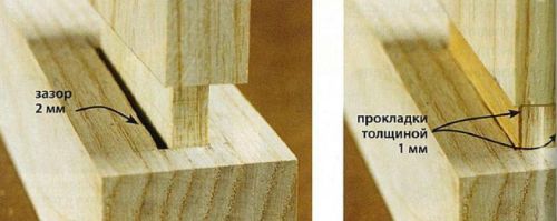
If, during trial assembly, the spike dangles in the socket, such a connection will not be strong. Filling the gaps with glue won't do any good, so don't be lazy to reinforce a piece that's too thin with wood. Cut out two overlays to make the spike a little thicker than required, and glue them on both sides. After drying, re-adjust the spike to the dimensions of the nest.
Turn a disadvantage into a virtue
Sometimes it is better not to hide the traces of repair, but to make them visible. In a too narrow ash thorn, two cuts were made and thin cherry wedges were inserted into them, which tightly pressed the narrow cheeks of the thorn to the edges of the socket. In other cases, such as countersunk joints, small chamfers or roundings along the ribs of the shoulders will make the loose seam less noticeable.

Replace Part
This can happen to any of us. Some mistakes don't make sense to fix for two reasons: (1) if no matter your skill and effort, the unsightly defect remains noticeable, or (2) if it's faster and easier to make a new part to replace the damaged one.
Details in wood products can be connected to each other with nails, screws or glue.
A nail is a fastener that consists of a head, a shaft and a point. Depending on the purpose, nails differ in diameter and length, as well as in the shape of the head (cap).
Before hammering nails, mark the places of their future location. When connecting parts with nails, a thin part is usually nailed to a thick one. The hammer is held so that the hand is at a distance of 20-30 mm from the end of the handle (Fig. 105, a). First, the nail is held with the thumb and forefinger of the left hand and light blows are applied to the hat with a hammer. After the nail has firmly entered the wood, the left hand is removed and the hammer is struck harder.
Rice. 105. Hammering (a) and pulling out (5, c) nails
If the nail is bent during hammering, it must be pulled out with tongs (Fig. 105, b) or a hammer with a special slot on the toe (Fig. 105, c). In order not to damage the surface of the product, a plank is placed under the pliers or the head of the hammer.
If the ends of the hammered nails protrude, they are bent around the metal mandrel and hammered back into the wood (Fig. 106). This increases the strength of the connection.

Rice. 106. Bending and hammering the protruding end of the nail
A hammered nail with a bent end is pulled out as follows: the bent end of the nail is bent with a screwdriver or chisel, leveled with tongs or pliers, knocked out with blows to the end of the nail with a hammer and the nail is pulled out by the head with tongs.
Rules for safe work
- Use only a working hammer with a well-fitted handle.
- Do not stand behind a friend working with a hammer.
- Hit the head of the nail in such a way that the direction of impact coincides with the axis of the nail.
- Don't leave your hammer on the edge of a workbench.
Screw connection
The connection of parts with screws is stronger than the connection with nails. A screw is a fastener consisting of a head and a threaded rod (Fig. 107).

Rice. 107. Screws with different heads: a - semicircular; b - secret; in - semi-hidden
Screw heads have slots - straight or cross-shaped grooves for screwing and unscrewing screws with a screwdriver. Installation sites for screws are marked in the same way as for nails.
A blind hole with a diameter slightly smaller than 0.9 of the screw diameter is drilled into the part into which they want to screw the screw, to a depth equal to the length of the screw part to be screwed. For thin screws, holes are pierced with an awl.
A through hole is drilled in the part to be attached with a diameter slightly larger than the diameter of the screw.
For countersunk and semi- countersunk heads of screws, the holes are processed (counterbored) with a large-diameter drill or a special tool - a countersink (Fig. 108, a, 6).

Rice. 108. Connecting parts with screws. Cutting a socket for a screw head: a - with a drill; b - countersink. Screwing in a screw with a screwdriver: in - with a semi-secret head; g - with countersunk head
After drilling the parts, they are connected, the screw is placed in the hole and screwed with a screwdriver clockwise (Fig. 108, c, d).
Rules for safe work
- Do not use a screw with a knocked-out slot.
- Use only a working screwdriver that fits the slot of the screw.
- Screw in the screw at a right angle to the workpiece.
- When screwing in the screw, do not support it with your hand.
- After screwing in the screw, clean the sharp burrs on the head with sandpaper or a file.
Connecting parts with glue
Many wood parts are joined with glue.
Adhesives are natural (natural) and synthetic (artificial). Synthetic adhesives have become more widely used (they are produced ready-to-use). Of the synthetic adhesives, PVA is used in school workshops.
PVA glue is a viscous white liquid. It is applied to the surfaces to be glued with a brush or swab.
Of the natural adhesives, casein and carpentry adhesives are used in school workshops. Casein glue is a yellowish powder. It is dissolved in water and mixed thoroughly. Freshly prepared glue is suitable for use within 3-4 hours, after which it hardens.
Before gluing, the surfaces of the parts are cleaned of sawdust, dirt, paint, then smeared with glue, kept for 2-3 minutes in air so that the glue is absorbed into the wood and thickens, and connected to each other. Then the parts to be glued are pressed in a clamp (Fig. 109) or in the clamps of a workbench and kept until completely hardened (about 24 hours).

Rice. 109. Gluing in a clamp: 1,2 - parts to be glued; 3 - glue; 4 - clamp bracket; 5 - clamping screw; 6 - clamp handle
Rules for safe work
- Glue parts only on backing boards.
- When applying glue, avoid getting it on your hands or in your eyes.
- Wash your hands thoroughly with soap after work.
Practical work No. 31
Joining wood parts with nails, screws and glue
Work order
- On unusable lumber, practice nailing wooden blanks of various thicknesses. Try prying out clogged nails with pliers or a slotted hammer. Connect the details of your product with long nails. Bend the protruding sharp ends of the nails and hammer them into the wood. Check the strength of the connection.
- On test pieces of wood, drill holes of the desired size and screw in various screws using appropriate screwdrivers.
Choose the screws of the required size to connect the parts of your product. Mark the locations of the screws. Connect the parts with screws.
- Prepare the workplace for gluing the parts of the product. Clean the surfaces to be bonded. Get your glue and brush ready. Apply with a brush an even layer of glue on the surfaces to be glued, let it dry for 2-3 minutes. Connect the parts and clamp them with a clamp, vice or workbench clamp. In the next lesson, check the quality of gluing.
New concepts
Nails, hammer, pincers, screw, slots, countersink, screwdriver, natural (carpentry, casein) and synthetic (PVA) adhesives.
test questions
- Where do nails, screws and glue meet?
- What is the difference between screw fastening and nail fastening?
- What can lead to screwing screws without first making holes in the parts?
- What safety precautions should be observed when connecting parts with nails and screws?
- Why are adhesive-coated parts exposed to air before bonding?
technology lesson
Subject: Types and methods of joining parts in wood products. Corner, middle and drawer stud joints, their elements and design features.
Program section:"Technologies for creating products from wood and ornamental materials based on design and technological documentation."
Class: 7.
Lesson Objectives:
1) Educational: to form knowledge about spiked joints and joints on dowels and dowels.
2) Developing: to help students develop the ability to choose a compound.
3) Educational: to continue the formation of a conscious need for work.
Lesson objectives:
1) Tell students about how to connect parts.
2) Explain and demonstrate the scope of the spike and dowel connection of parts.
3) Explain how the connection is calculated.
Lesson equipment:
1) Material and technical base: Samples of connecting parts with spikes and dowels.
2) Didactic support of the lesson:
Technology grade 7. Tishchenko A.T., Samorodsky A.T., Simonenko V.D. – Bryansk 1996
Teaching methods:
Verbal methods (explanation, conversation);
Visual methods (demonstration of visual aids).
Lesson type: lesson explaining new material.
Lesson structure:
Organizational moments (2 min);
Updating of basic knowledge (6 min);
Presentation of educational material (30 min);
Setting homework (2 min).
During the classes:
1) Organizational moments:
Greeting students;
Student attendance checks;
Setting up students for work;
Message about the topic and purpose of the lesson.
2) Updating of basic knowledge:
Let's remember in what ways you can connect wood parts (screws, nails, bolts, gluing). Where can these types of compounds be found?
3) Presentation of educational material:
The topic of our lesson: “Types and methods of joining parts in wood products. corner, middle and box tenon joints, their elements and design features.
The simplest carpentry connection can be represented as spike-to-socket connection or in the eye(Figure 11). A spike is a protrusion at the end of the bar (Figure 11), a socket is a hole into which the spike enters. Spike joints are divided into corner end, corner middle and corner box.
In the practice of amateur carpenters, there are very often corner end connections. To calculate the elements of the corner end (Figure 13) and corner mid-connections (Figure 14), use the data in Table 4.
Let it be necessary to calculate the connection on the "mustache" with a plug-in through flat spike (UK-11). The thickness of the connected bar is known (let s 0 = 25 mm). Then, taking this size as a basis, we determine the size s 1 . According to table 3, s 1 =0.4 mm, s 0 = 10 mm.
Let's take the UK-8 connection. Let the dowel diameter be 6 mm, then l (we choose the average value - 4d) is 24 mm, and l 1 \u003d 27 mm. The pin connections are made symmetrically to each other and with respect to the plane of the part, therefore, according to (Figure 14, h), the distance from the center of the hole for the lower pin to the center of the hole for the upper pin will be at least 2d, or 12 mm; the same distance from the center of the dowel hole to the end of the part to be joined.
Figure 14 shows the circuits cornermiddle(T-shaped) connections, for which, when calculating, it is necessary to observe the following main dimensions of spikes and other elements:
In the US-1 and US-2 connections, the use of a double spike is allowed, while
s 1 = 0.2s 0 , (3)
where s 1 - spike width, in mm;
s 0 is the width of the part, in mm.
l 1 = (0.3…0.8) B, (4)
where l 1 - the depth of the spike, in mm;
B is the height of the part, in mm.
l 2 \u003d (0.2 ... 0.3) V 1, (5)
where l 2 - the depth of the spike, in mm;
B 2 - the height of the part, in mm.
In connection US-3
s 1 \u003d 0.4s 0, (6)
where s 1 - spike width, in mm;
s 0 is the width of the part, in mm.
s 2 \u003d 0.5 (s 0 - s 1). (7)
where s 1 - spike width, in mm;
s 0 is the width of the part, in mm.
In connection US-4
s 1 \u003d s 3 \u003d 0.2s 0, (8)
where s 1 - spike width, in mm;
s3 - eye width, in mm;
s 0 is the width of the part, in mm.
s 2 \u003d 0.5 X [s 0 - (2s 1 + s 3)], (9)
where s 1 - spike width, in mm;
s3 - eye width, in mm;
s 0 is the width of the part, in mm.
In connection US-5
s 1 \u003d (0.4 ... 0.5) s 0, (10)
where s 1 - spike width, in mm;
s 0 is the width of the part, in mm.
l = (0.3… 0.8)s 0 , (11)
where l is the tenon depth, in mm;
s 0 is the width of the part, in mm.
s 2 \u003d 0.5 (s 0 -s 1), (12)
where s2 - eye width, in mm;
s 1 - spike width, in mm;
s 0 is the width of the part, in mm.
In connection US-6
l = (0.3… 0.5)s 0 , (13)
where l is the tenon depth, in mm;
s 0 is the width of the part, in mm.
In connection US-7
d \u003d 0.4 at l 1 l by 2 ... 3 mm;
In connection US-8
l \u003d (0.3 ... 0.5) B 1, s 1 \u003d 0.85s 0.
Table 4 - Dimensions of spikes and other elements of the corner end
connections
| Connections | ||||
End of table 4
| Connections | ||||
| l1 l by 2…3 mm | ||||
| l1 l by 2…3 mm | ||||
Note. Sizes 0 , B and B 1 are known in each particular case.
Often use the method of connecting to a dowel (nagel). A dowel is a cylindrical stick made of birch, oak, etc. It is evenly machined and hammered into pre-drilled holes - channels pre-lubricated with glue. Holes for dowels are made in both parts at once. The dowel should enter the hole tightly, with the help of mallet blows. The drill for preparing the holes must match the size of the dowel. To reduce the diameter of the dowel, grinding with sandpaper or a bastard file is used (risks are made not across, but along the dowel).
At connection selection it is necessary to consider the nature and magnitude of the load, as well as how the connection will resist the load.

a - in the nest; b - in the eye; 1 - spike; 2 - socket, eyelet
Figure 11 - The simplest spiked joints
AT corner box connections spikes are repeated many times. Basically, three types of such connections are used: on a straight open spike (Figure 12, a); open “dovetail” on the spike (Figure 12, e); on an open round plug-in spike - dowel (Figure 12, h).
From a comparison of the resistances of two connections (half-wood with a screw and a dovetail), it can be seen that the connection in the dovetail can withstand a load three times greater than the connection in half-wood with a screw. Based on this and a number of other examples, we can draw the following conclusions about the appropriateness of using certain joints: joinery knitting should be selected in accordance with the magnitude and direction of the load on the joint;

a - single; b - double; in - multiple;
g - round; d - "dovetail"; e - one-sided "dovetail"; g, h - serrated.
Figure 12 - Types of spikes
the load must be perceived directly by the product design itself (additional fasteners can be a screw, a metal square, a dowel, etc.); knitting with gaps is not allowed.
Gluing should be done only with prepared surfaces: the rougher, for example, the surface of the dowel, the more reliably it will stick to the array.

a - open through single spike - UK-1; b - on the awl open through double - UK-2; in - on the awl open through triple - UK-3; g - on an awl with a semi-dark through - UK-4; d - on an awl with a semi-dark end-to-end UK-5; e - on an awl with a descendant of non-through - UK-6; g - on a spike with a descendant through - UK-7; h - on spikes round plug-in, non-through and through - UK-8; and - on the "mustache" with a plug-in non-through round spike - UK-9; to - on the "mustache" with a plug-in flat toe spike - UK-10; l - on the "mustache" with a plug-in through flat spike - UK-11.
Figure 13 - Angle End Connections

a - on a single non-through spike - US-1; b - sewed single blind into the groove - US-2; c - on a single through spike - US-3; g - on a double through spike - US-4; d - into the groove and non-through crest - US-5;
e - into the non-through groove - US-6; g - on spikes round plug-in non-through - US-7; h - on the spike "dovetail" blind - US-8.
Figure 14 - Corner center joints
More simple than spiked, but less durable is the connection of wooden parts with dowels (Figure 15). Dowels- these are round inserts inserted into the holes of two connected parts.
The surfaces of the two parts connected by dowels must be precisely fitted to each other, and the holes for the spikes must be drilled exactly opposite each other, i.e. coaxially.

Figure 15 - Connecting parts with dowels
The diameter of the dowel should be 0.4 of the thickness of the parts to be joined. Holes are drilled under the dowels with drills of the same diameter as the dowel diameter to a depth of 0.5 dowel length plus 2 ... 3 mm.
The distance from the end of the part to the center of the dowel hole must be at least two dowel diameters.
The most critical operation is drilling holes for dowels in two parts. The centers of the dowel holes are usually marked with a thickness gauge and a joiner's square. Figure 16 shows the sequence of parts assembly with dowels.


a - markup; b - drilling holes at the end; c - marking, drilling holes on the plate and connecting
Figure 16 - The sequence of assembly of parts with dowels
Before connecting the parts, the dowels are smeared with glue, inserted into the holes and the parts are connected by pressing them for the duration of gluing, for example, with wedges on the lid of the workbench.
Connecting parts with screws in the dowel.
To connect the parts at an angle with screws, a hole is drilled at the end in the wood and a dowel smeared with glue is driven into it (Figure 17). The essence of the connection is that the screws are weakly connected to the end of the part, but firmly screwed into the dowel.

Figure 17 - Connecting parts with screws into the dowel
4) Statement of homework:
Paragraph §7, 8, 9 from the textbook pages 37 - 47, read and answer the control questions in the workbook. Write in a notebook at least three products connected by dowels and tenon joints. Calculate the dimensions of the spike joint for boards with a section: 20 * 100 mm (1 option), 40 * 250 (2 option).
JOINING THE PARTS ON THE NAILS Many of the woodwork you will be making in the training workshops will contain multiple pieces. They are connected to each other in various ways. The process of connecting parts into a whole product is called assembly. Many wood products that you will make in the training workshops contain several parts. They are connected to each other in various ways. The process of connecting parts into a whole product is called assembly.
Depending on the location of the parts in the products, end and middle connections are distinguished. They can be made with nails, screws or glue. End Connections Middle Connections The industry produces nails of various thicknesses, lengths and with different heads. The main tools used to connect parts on nails are a carpenter's hammer, pliers and an awl. Carpentry Hammers Awl Pliers
When connecting parts with nails, a thin part is nailed to a thick one. In order for the connection of parts to be reliable, the length of the nail must be 23 times the thickness of the nailed part. The diameter of the nail must be less than the thickness of the part being nailed, otherwise a crack may appear in the part. The place where the nail is driven in must be at least half the thickness of the part from the edge or end of the part. It is advisable to pre-pierce it with an awl. The nail begins to be hammered with gentle hammer blows, and when it enters half of the rod, it is necessary to hit harder. Hammer blows on the nail are applied from above, directly on the hat, and not at an angle to the nail shaft. The strongest connection is obtained when the nail is driven across the fibers or at some angle to them. If the nail went askew or bent, don't worry! Such a nail must be removed with a hammer with a special slot on the toe or with pliers. Punching holes with an awl Hammering nails Hammering nails at right angles to the grain of the wood Bent nails can be straightened on a metal bar or hard board and used in further work. In order not to damage the product, a piece of wood or plywood is placed under the jaws of the pliers or the head of the hammer. Pulling out nails with pliers Pulling out nails with a hammer
ATTENTION! You can only work with a serviceable tool, it must be used strictly for its intended purpose. When working, the hammer must be kept at a distance of 2030 mm (2 3 fingers) from the free end of the handle. Do not leave a carpenter's hammer on the edge of a workbench. You can not stand behind the back of a person working with a hammer. The tip of the awl should be directed away from the worker.
CONNECTION OF PARTS ON SCREWS Over time, the nail connection weakens: the nail can swing and even fall out completely. The connection of parts on screws is much more durable. Over time, the nail connection weakens: the nail can swing and even fall out completely. The connection of parts on screws is much more durable.
A screw is a fastener that consists of a head and a threaded shank. The head of the screw has a slot for a screwdriver. The slot can be straight and cruciform. Screws differ in the type of heads, which are semicircular, countersunk and semi-secret, as well as in the length of the rod. Most often, countersunk head screws are used. Such a screw does not protrude above the surface of the part. A screw with a semi-circular head A screw with a countersunk head A screw with a semi-counter-sunk head The places for installing the screws are marked in the same way as for nails. It is difficult to screw a screw into a part, therefore, in the workpiece, before installing small screws, a hole is made with an awl to a depth equal to about 2/3 of the screw length. For a countersunk head, a large diameter drill widens the inlet. The screw is inserted into the hole and screwed with a screwdriver clockwise. A screwdriver is selected in such a size that the width of its working part is equal to the width of the slot. The shape of the working part of the screwdriver should be the same as that of the slot. For thick and long screws, holes are drilled with drills. Their diameter is 4/5 of the diameter of the screw shaft, the drilling depth is approximately equal to half of its length.

ATTENTION! Use only a screwdriver that fits exactly into the slot of the screw head. The screw must be screwed in at a right angle to the parts. When assembling parts, do not use screws with a knocked down slot. Screws lubricated with machine oil or soap are easier to screw into the part. The burr on the head of the screwed screw must be removed with sandpaper.

Most often, wood glue is used to obtain adhesive joints. It comes in the form of grains or dark brown tiles. Glue is prepared in a special glue pot and used hot. The glue should not be very thick and without lumps. The glue is applied with a thin layer evenly on the surface of the parts to be joined with a brush and compressed with a clamp fixture. Wooden clamp Metal clamp After exposure (its time is determined taking into account the glue used), the glued parts are released from the clamp, the remaining glue protruding from the seams is removed. Sometimes, for gluing wooden parts, synthetic universal adhesives such as PVA, Supercement, BF are also used, which are widely used in everyday life for gluing products from other materials. However, synthetic adhesives emit harmful fumes. Therefore, their use requires special conditions: good ventilation of the premises, the presence of warm water for washing hands after work.


Finishing the final treatment of an assembled product in order to improve its appearance and protect it from moisture, insect damage, etc. Finishing a product includes several operations: cleaning surfaces, coating with dyes, applying patterns by burning, etc. These operations can be performed before assembly or after assembly of parts. Depending on the intended use of the product, some operations may not be applicable. Cleaning irregularities after sawing, as well as rounding the sharp corners of the workpiece, is carried out with a rasp or a file with a large notch. When filing, the left hand of the worker should lie on the toe of the tool, not covering it. Press the tool only when it moves forward. Cleaning of parts with a file Cleaning of parts after manufacturing is carried out with a sandpaper. It is based on cotton fabric or thick paper, on one side of which small grains of glass or hard minerals are glued.
For convenience, a piece of sandpaper is attached to a wooden block. It is convenient to grind small parts as shown in the figure. Cleaned parts or products are often painted with cotton paint, watercolor or gouache. A special stain is also used. Sometimes wood products are varnished, which gives it a beautiful appearance and protects the surface from moisture. Regardless of the type of dye, it is applied with a brush or swab with a piece of cotton wrapped in gauze. Cover the surface first along the fibers, then across. Applying color with a brush Applying color with a swab
