Re-grounding in a private house. Ground loop of a private house. What to avoid when installing a ground loop - the most common mistakes
A private house is an opportunity to relax every week with friends or family in nature. You don't even need to have a car. Electric trains, minibuses and buses run from megacities to nearby cities and villages all the time.
But having a private house somewhere in the countryside is not all. It is necessary to take care of the safety of every person who is there. To exclude the possibility of electric shock, it is worth making a ground.

Grounding guarantees the safe operation of household appliances. Moreover, if you have an electric stove or a washing machine installed, then you simply cannot do without it. In the latter case, the failure of a household appliance can lead to extremely disastrous consequences.
Important ! If you live in a private house without grounding, then by doing this you create a dangerous situation indoors for your loved ones and relatives.
Making grounding in a private house with your own hands is not so difficult. The main thing is to follow the standards and use high-quality components and materials. Many are trying to save money and make zeroing, motivating such an act by the fact that grounding is not necessary in a 220 V network.
However, this is not entirely true. Indeed, doing grounding in a 220 V network is not a mandatory safety standard in a private house. But such a step allows you to largely protect each tenant from electric shock.
Important ! If the power supply is from a 380 V network, then grounding will have to be done. This will allow every person living in a private house to feel safe.
Why do we need a ground loop

Let's start with a school biology course. A person is 70% water. That is why electric shock can cause us significant harm. Internal organs take a lot of damage. The body begins to convulse. Therefore, it is extremely important to quickly remove the victim from the current source. In the worst case scenario, after an electric shock, the heart stops.
Of course, no one will climb to bare wires to experience new sensations. But in case of failure, the cases of some devices become full-fledged electrical conductors. One touch is enough to grab the discharge. To prevent this from happening, it is enough to make grounding. In this case, every person living in a private house will be under reliable protection.
Let's consider a real situation. From long operation, the heating element inside the boiler collapsed. As a result, electricity began to be transmitted through the nichrome spiral into the water. Now every touch on the body of the boiler is deadly.
To eliminate the risk of electric shock, all parts of the device capable of transmitting current are grounded. In this case, the voltage that occurs during a breakdown will go exactly to the ground, without carrying any threat.
To better understand how to make grounding in a private house. Consider an example of such protection against electric shock at industrial facilities. The ground conductor is connected to the body of each machine and control panels. Such a measure allows you to insure each worker from a possible electric shock.

To make grounding for household appliances in a private house, you will additionally need to connect a protective conductor. It is connected to an outlet into which the plug of a certain device is inserted.
When the neutral conductor breaks, not only electricity disappears, the protection circuit breaks. If this happens, then grounding will be a neutral conductor. At the same time, the performance of each device will be preserved, as well as protection.
Attention ! The main role of grounding in a private house is to ensure safety when touching the housings of household appliances.
We make grounding in the country
What should be high-quality grounding
Before you make high-quality and reliable grounding in a private house, you need to know the basic technical requirements for structures of this type. First, consider the meaning of the concept itself. In fact, this is an electrical circuit that provides a safe output of electricity in the event of a breakdown of household equipment.

Structurally, grounding can be divided into three components:
- Grounding conductor. This part is a collection of conductors. Each of them is in constant contact with the ground.
- Ground conductor. This structural element connects the device to be grounded with a ground electrode.
- Grounding device or grounding- grounding + grounding conductors.
If you look at it objectively, then the ground electrode in a private house is a set of metal conductors that go into the ground. Any quality grounding must have an appropriate spreading resistance. This parameter indicates how easily the current enters the ground.
Important ! Resistance is like a valve. It blocks the flow of electricity. The smaller it is, the better and more reliable grounding in a private house.
Many parameters influence the strength of resistance in the grounding of a private house. Therefore, before you make this security system from electric shock in your home, you need to learn about them.
The first thing you need to pay attention to is at what depth the ground electrode lies.. Also, the resistance is affected by soil moisture and the number of conductors. It is best to make a contour around the entire perimeter of the house. If this is not possible, stop your choice on the north side. It is there that the moisture content of the soil is maximum.
There are special requirements for grounding conductors. It is not enough that they are made of quality steel. The thickness of the conductor must be at least four millimeters. In this case, the minimum diameter of the pipe is 32 mm; vertical bars 16 mm and more, horizontal 10.
Mounting

To make a system of protection against electric shocks in case of damage to household appliances, you need to choose a place where the conductors will enter. This is where the vertical rods will need to be hammered.
Important ! Before you do the installation of the device with your own hands in a private house, make sure that there are no communications in the place where you will lay the ground loop.
Ideally, you must first coordinate the work with the relevant services, such as heat and gas supply organizations. Please note that the restoration of a damaged heating or gas network is extremely expensive.
The easiest way is to make a linear contour, and place it parallel to the blind area. Some builders go for a variety of tricks, making grounding in the form of a triangle or polyhedron. Ideally, you should encircle the house around the entire perimeter. True, this will require a lot of materials and time.
Advice ! The main advantage of linear mounting is that, if necessary, the structure can always be extended.
You need to start installing a protective system in a private house by cutting off a corner or a rod. Its length should be two meters. The end should be pointed. You can use a hand drill to drill holes. If there is no such accessory in the household, use an ordinary shovel.

After the pit is dug near a private house, you need to hammer in the ground electrode. If the first rod entered the ground easily. The second can be made half a meter longer. The main thing is not to overdo it. Three meters is the maximum length.
Five grounding conductors are enough to make reliable protection for a private house. Trimming of the rods is done not below ground level. Approximately, this is somewhere around 20-30 cm. Between the ground electrodes, you need to dig a groove that will connect them.
Grounding elements in a private house can be connected by welding. If there is no welding machine available, you can do the same, but with ordinary bolts. Welding is still preferable, as it provides a higher level of reliability. It also increases the life of the entire structure.
Important ! The bolted connection must be tightened periodically.

We take measurements
After you make the installation of the ground loop in a private house with your own hands, you will need to take the appropriate measurements. The first thing you need to test is the resistance. The normative indicators are as follows:
- Network 220 V - resistance within 30 ohms.
- Network 380 V - resistance 5-10 ohms.
- Rare rocks of the soil, for example, rocky - 100 ohms.
The most high-quality ground loop should be at a 380 V network. In addition, for three-phase wiring, grounding in a private house is mandatory. Luckily, you can make your own.
Laying a ground electrode

After the testing has been completed and the indicators correspond to the norm, it is necessary to lay the grounding conductor from the circuit to the shield. The conductor diameter cannot be less than 8 mm.
The steel conductor is brought in through the wall of the house. You can choose the place yourself, the main thing is that it is convenient for you to work. Then grounding in a private house will be done efficiently and reliably.
At the end of the steel conductor, which is part of the deceleration, a bolted connection must be formed. You can cut a thread or weld a bolt. The tip must be pressed into a copper wire. The diameter of the last one is 4 mm. It is best to hide it in the plinth.
Attention ! Breaking the ground conductors with switching devices is prohibited.
Results
As you can see, making a ground loop with your own hands is not so difficult. Moreover, you can cope with such work without using any special equipment. The effect of such a protection system will be more than useful and will be able to protect the residents of the house from domestic injury.
Do-it-yourself grounding in a private house will help not only to avoid danger, but also save your budget. After all, electric current can cause irreparable damage to human health and life. In an emergency, even touching a conventional washing machine or microwave oven can lead to tragic consequences. If there is a break in the zero phase, then the body of electrical equipment becomes dangerous, while the ground loop acts as a phase through which the electric current goes to the ground.
Grounding installation is a necessary measure for any building, whether it is a private building, an apartment building or a cottage. In order to avoid the occurrence of a short circuit, as well as for the safe operation of any electrical appliances, grounding is simply necessary. How to make grounding? The voltage of 220 volts and 380 volts require a different approach and perform different actions, in fact they are two different networks. At a voltage of 220 V, it is possible to carry out standard grounding without arranging the circuit, but for the second option (380 V), a ground circuit is required.
In any case, if you are installing new wiring or trying to reanimate an old one, grounding must be done.
Contour installation, photo:
Ground Loop - Conductor Requirements
Let's figure out what a ground loop is: in fact, these are buried vertical ground electrodes connected to each other by horizontal ones. This design is accompanied by a grounding conductor, the main function of which is the connection of the circuit and the panel of the electrical panel. According to the rules for the installation of electrical installations (edition No. 7), it is recommended to use a steel angle for vertical conductors (50 × 50 × 5 mm - ideal), for horizontal conductors - a metal strip (with a rectangular section, 40 × 4 mm in size). The grounding conductor must be made of a round steel bar with a cross section of 8 or 10 mm². The exact parameters of the grounding elements are described in more detail by the rules for the installation of electrical installations (PUE) - section 1.7
When describing metal elements, the idea of using reinforcement suggests itself - this is absolutely impossible to do! Reinforcing bars have a surface hardened layer - this factor disrupts the uniform passage of electric current over the cross section. Also, this material is subject to oxidative, corrosive processes.
Materials for horizontal and vertical elements, photo: 
How to make grounding - circuit installation
First, we make a contour: for this, next to the house (not exceeding a distance of 1 m from the foundation), we mark an isosceles triangle on the ground. Then, along the borders of the received triangle, we dig a trench, a depth of 1 m will be enough. The width of the trench should be such that it is convenient for you to carry out welding work (0.5-0.8 m). Initially, horizontal ground electrodes are placed along the perimeter of the triangle, after which vertical ones are driven in at the corners - they should be buried to a considerable depth - 2 or 3 meters. This is easy to do with a sledgehammer; for the convenience of the process, it is better to sharpen the corner itself at the end.
Now install the ground loop. The requirements are as follows: the edges of the vertical ground electrodes must protrude 25 cm from the place of penetration. To close the circuit, we weld the horizontal ground electrodes to the vertical ones. The connection of parts must be carried out exclusively with the help of a welding machine and nothing else. After that, we connect the circuit to the electrical panel: we take a steel wire (section 10 mm), weld it to the circuit, put it in a trench towards the shield, weld an M6 (or M8) bolt to the end of the wire - it is necessary to fix the wire. If you do not have a steel wire, then a steel strip (the same one used to make horizontal ground electrodes) can be used as a grounding element.
Ground loop, photo: 
According to practical experience, steel strip is more suitable for grounding than wire, but it is quite difficult to bend it at the required places in the trench. Do not be too lazy to treat the welding places with special anti-corrosion agents, the main thing is that you should never use ordinary paint instead of this agent! Metal parts should be in extremely close contact with the ground, and a layer of paint prevents contact, creates resistance. After all the manipulations carried out, fill the trenches with earth, on this the process of arranging the contour can be considered completed. All the above actions are also applied when installing lightning protection - the process is the same.
Welding of contour details, photo: 
Separately, it is worth mentioning ready-made prefabricated grounding kits (for example, ZANDZ, KZTs-5, KZM-3, KZM-10, KZM-20), which are sold in electrical equipment departments. Such a grounding kit already has all the necessary details for arranging the system: copper-plated pins, a guide head, a lug, clamps, brass couplings for connection, as well as a special anti-corrosion agent. This is a rather convenient solution, since when you purchase this kit, you will receive all the necessary elements for high-quality grounding.
Connecting the electrical panel - the final stage of grounding
This process should be carried out by a qualified specialist or, at least, by a person who has repeatedly dealt with similar work. Beginners who are familiar with the installation of grounding by hearsay or have “surfed” the Internet about the stages of the process - even if they have thoroughly studied the theoretical part - cannot perform these actions. This matter must be taken extremely seriously, because any wrong step poses a threat to your life and health.
Near the place where the circuit exits the trench, a junction box must be installed on the wall of the house. Inside this box, a tire is mounted with two fasteners for bolts. The ground loop strip is connected to one fixture, a copper cable must be connected to the other, its cross section must be more than 10 mm². It is important that the cross section of this cable is not smaller than the cross section of the lead wire. Instead of bolting, you can use a welding machine to connect these parts. After that, the copper cable must be laid to the electrical distribution panel, then connected to the ground bus. All ground wires will depart from this bus. The main condition for this process is the requirement for the integrity of the grounding cable at all stages of laying - it must be solid, not have breaks. Checking the grounding, measuring its resistance is carried out at the last stage of the whole process.
The direction of the strip to the house, photo: 
In private houses, there may be different-phase electrical networks, so the grounding of 220V and 380V must be separated. However, it should be borne in mind that they can be directed to the same circuit. Sometimes on the relevant forums you can see comments about the fact that for a 220V network it is not necessary to equip a ground loop, you can only zero. In fact, the way it is, but still the presence of a circuit will by no means be superfluous for a 220V power supply.
If you yourself are grounding 380 V, then the presence of a circuit is a prerequisite. 380V power transmission is very demanding on the quality of the ground loop.
How to check grounding
The check is carried out after all installation work. There are special devices for this (for example, Extex GRT300, TH200, EP183M), the process of checking the grounding is the same for them. First, two pins should be deepened (the depth should be at least 50 cm), and the area on the tire should be cleaned. Then, according to the instructions attached to the device, the wires of the corresponding color must be connected to the ground bus and to the pins. Measurements are carried out as indicated by the instructions for the device. According to the PUE, the resistance indicator for a 220V electrical network should not exceed four ohms. Before burying the pins, make sure that no underground utilities pass through this place.
The phase in the outlet can be checked using a special tester; it should be in only one of the outlet holes. When checking the ground contact, the indicator light of the tester should not light, if it is on, then you need to check the connection or identify possible damage. When opening the outlet (of course, while the electricity must be turned off), you should find three wires connected, if there are two, and there is a jumper between the terminals (zero-ground) - this is an indicator that zeroing has been done, but not grounding. If everything is done correctly, all three wires are in place, then the socket closes, the electricity turns on, the phase-zero voltage, phase-ground, zero-ground voltage is checked using a multimeter. If there is no voltage at phase-zero, then this may indicate a break in the neutral wire, if there is no voltage at phase-ground, then this means that there is no grounding. If there is voltage at the phase-to-zero and phase-to-ground ratio, but there is no voltage at zero-to-ground, then, apparently, this indicates zeroing.
If you don’t have the appropriate measuring instruments at hand, but you need to check the grounding, you can use the old proven method - a light bulb with a cartridge and two wires. The ends of the wires must be stripped and inserted into the socket, while the light should be on. Next, remove one of the wires and touch it to the grounding antenna, if during these actions the light does not light up, then in the same way check the other wire. If a residual current device (RCD) is triggered, then this is an indicator of the presence of grounding. If there is no protection, but there is a ground-phase connection, the light will also be on, but its glow will be much brighter than when the phase-zero is connected.
Do-it-yourself protective grounding will protect you from possible electric shock, and your household appliances from breakage. Today we can no longer imagine our life without a variety of electrical appliances that make our life easier. Electricity is of great help to us, but it also carries a mortal danger if you do not know how to properly handle it. The organization of competent grounding is the most important stage in the installation of the wiring of any home. Qualified electricians know how to properly ground in a private house, but if you take on this business yourself, it will be better if an experienced person is next to you.
For a grounding device in a country house or in the country, you will need a little patience, building materials, a minimum of tools, and a little knowledge gained from this article. We will not think about what kind of grounding is and what grounding options should not be adopted. Also, let's not bother with information about the equivalent soil resistivity and the values of the calculated climatic coefficients of soil resistance seasonality.
We will go exclusively in the best way - we will take the successful experience of the already completed installation of grounding, which was carried out on the basis of an approved project, it was checked and the competent services gave the appropriate operating permit.
First, let's roughly calculate what we need:
Tool
- Welding machine and mask for welding.
- Sledgehammer 5-8 kg.
- Shovel (bayonet and shovel).
materials
- Steel corner 50 x 50 x 4 mm X 3 m - 3 pcs.
- Steel corner 50 x 50 x 4 mm X 1.5 m - 3 pcs.
- Steel rod D - 14 mm - length - from the place of installation of the ground loop to the house + height to the gable + a separate bar from the ground loop to the house and up to the ridge (when installing lightning protection).
- Electrodes 3 mm.
- Wire 4 x 4 mm 2 - length, from soldering with a rod, to the shield.
- Corrugated pipe for cable - length, from desoldering with a rod, to a shield.
- Terminal for connecting rod and wire.
Laying the outer part of the ground
Let's start with what we got. This is a country house in the village, that is, the requirements for electricity and security are at a high level.
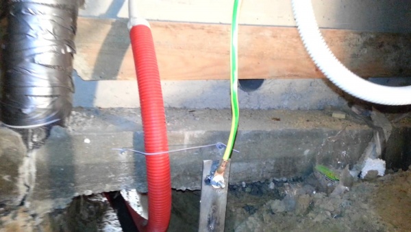
- Pole wires powering the house.
- Rod 14 mm. It comes out of the ground and rises to the place of desoldering and lightning protection.
- The place of desoldering (connecting) grounding, and power wires from the pole.
- cable 4 x 4 mm in a corrugated pipe going to the shield in the house (3 phases, zero with earth in one core)

Wires from the pole to the house.

2 rods welded to the ground loop and coming out of the ground. 1 for shield, 2 for lightning protection.

- Corrugated wire - ground with zero and 3 phases entering the house.
- Wooden pads for cables and grounding rods - to avoid direct contact with the house.

Lightning protection, arranged on the ridge of the house.

The arrow shows a grounding rod that comes out of the ground and rises to the ridge to be connected to the lightning protection cable. For the lightning protection device, a steel cable was used, with a diameter of 8 mm, the tension between the supports is achieved due to the door spring.

Location for wiring. 1 - 3 phases; 2 - zero connected to the ground.

This is the same place of desoldering from a closer angle.

Wire 4 x 4 mm. In the corrugation, coming from the street into the house, on the electrical panel.

Electrical shield. Separately, we see an earthen vein that is in contact with the shield due to the standard bolted connection located on the shield door.
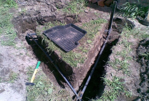
And now what we have left behind the scenes, that is, underground.

Where we decided to bury the ground loop, we tear off a moat in the form of an equilateral triangle - external dimensions 1.8 x 1.8 x 1.8 m, width - 40-50 cm, depth 1 m.

Accurately marking three points, between which the distance of 1.5 meters we hammer in the electrodes - 3 steel, 3-meter corners. This is where you really have to work hard. Corners on one side can be sharpened with a grinder - for better entry into the ground. Corners must be hammered strictly vertically. It will be necessary to drown them at half the height of the moat, that is, half a meter from the ground level, it will turn out deeper - please, it will only be inconvenient to carry out welding work.

We carefully weld three one and a half meter corners to the electrodes hammered into the ground - the corners, we weld all adjacent planes well.

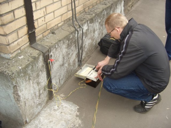
Then, you need to measure the resistance of our grounding. For reference, the maximum allowable resistance for a single-phase wiring system is 30 ohms. Special, competent services in this matter hammer 2 electrodes into the ground and check with their device. For us, in order to be sure that the contact of our circuit with the ground is good and the resistance does not exceed the permissible parameters, that is, our work is not in vain and the grounding device with our own hands in your private house will be really reliable, you need to do the following:
Find the socket closest to the buried steel structure in the house and use the indicator to determine the phase.
Ground resistance test

Then take a lamp with a cartridge and power one of the lamp contacts from the phase in the socket, and connect the second to the ground loop. If the lamp burns brightly, then the connection with the ground is good and the resistance does not exceed the permissible values. If the lamp burns dimly or does not light at all, then the resistance exceeds the permissible values, such grounding will not protect the house. It will be necessary to increase the area of the ground loop and check again.

If the test is successful - the lamp burns brightly, the resistance is acceptable, then we weld one end of a metal 14 mm rod to the steel corner of the ground loop and lay it to the house in the ground. Then we lift it under the pediment and commute with at least 4 copper squares from the core and lay it in the shield. In the shield, we connect the earth to the body of the shield using a standard, bolted connection and distribute the earth among household appliances and sockets. We return the excavated soil to the ditch.

A lightning protection device, when the ground loop is ready, will take a little time and save you from possible troubles.
Typical grounding device error
In this video, the grounding device is made, say, with a C grade with a plus. Reinforcement or corrugated metal is not used as electrodes or metal driven into the ground, since by its properties it is not able to stay in an aggressive environment for a long time - this leads to its inevitably rapid corrosion, respectively, such grounding will fail quickly enough. When using a rod, only a smooth surface is justified. And the method of hammering metal into the ground with the help of a perforator, frankly, pleased me, for this respect to the author.
Grounding is a necessary measure in any private house or apartment. This guarantees the safe use of electrical appliances and protects against the risk of short circuits. If you need to do grounding in a private house with your own hands: 220 V and 380 V are two networks for which you will need to perform different grounding steps. For the first option, normal zeroing without installing a loop is suitable, but for the second, a mandatory ground loop.
Do I need grounding in a private house
Grounding enhances the safety level for your electronics. Here's how it works:
- Electricity travels the path of least resistance. If an appliance, such as a toaster, breaks down, electricity can enter the metal sheath on the outside of the toaster.
- Touching it can result in severe shock, injury, or even death. But if the electrical system is grounded and the toaster is connected to ground, no electricity will flow outside the toaster. It will go into the ground. .
- The electrical system can be grounded using various types of devices. A "ground wire" is simply a wire connected to your electrical system that is firmly inserted into the ground. The metal pipes (called "conduit" by electricians) that hold and protect electrical wiring can also act as a ground.
Why is grounding necessary in a private house?
Grounding not only protects people, but also sensitive electronics.
Without grounding, electrical charges build up in wiring and create slight but permanent damage to sensitive electronics. This damage can shorten the life of computers, phones, any electrical appliance with "smart" (computer) components, and possibly a refrigerator or dryer.
Electric current is a steady flow of electrons. Just as water runs down a hill, electrons move towards a positive charge, such as the soil (like lightning strikes) or a ground terminal on a charger. Metal and water are good conductors of electricity because they hold electrons weakly and are relatively dense, allowing electrical current to flow through them.
Electric current requires a circuit of conductive material. A properly built electric fence is a potential circuit. Electric current is transmitted from the power source through the fence wires. The ground rods are installed and connected to the power supply. When a living organism touches the circuit, the circuit is completed, allowing electrical current to flow from the power source, through the fence wires, through the body, into the damp soil, to the ground rods, and back to the ground terminal on the power source.
Building an electric fence means building a potential circuit: a circuit that closes properly when something touches the hot wire and the soil at the same time.
How is grounding different from lightning rod
Light shielding systems are a first-class conductive network, modeled after a Faraday cage, used to protect a structure from the effects of lightning (direct or indirect).
The grounding system is a network of low quality conductors designed to allow the transfer of electrical energy (from a high quality network) from the network of conductors to the surrounding natural soil (earth). Many different high-end wiring networks rely on the grounding system to discharge unwanted electrical energies. This includes the lightning protection system, but also includes the main electrical grounding network, building structural steel, telephone and internet grounding systems, server computer room grounding systems, static grounding systems, gas pipeline grounding systems, water pipe grounding, and more.
Thus, the simplified relationship between a lightning protection system (LPS) and an earthing system is that the LPS captures electrical energy and directs it from the structure to the earthing system, which then dissipates the electrical energy into the earth.
Grounding device in a private house
The grounding scheme in a private house includes the following elements:
- three vertical grounds that are driven into the ground. They can be made in the form of an angle;
- three horizontal steel strips that connect the vertical ground;
- a steel strip that acts as a conductor between the ground loop and the switchboard.
Types of ground loops in a private house
Ground loops can be in the form of a triangle, rectangle, oval, line or arc. The best option for a private house is a triangle, but others are quite suitable.
Types of grounding in a private house can be mixed, that is, combine different types of circuits and materials.
Triangle
The pins are driven to a depth of 2.5 meters, then the distance between them should be 2.5-5.0 m. In this case, when measuring the resistance of the ground loop, optimal indicators are obtained.
Linear ground loop
An alternative method that consists of a string of pins. It is performed when it is impossible to make a normal contour. Proper grounding in a private house begins with the arrangement of the circuit.
Elements of the ground loop
A group circuit is an unintentionally induced feedback loop assembled by two or more circuits that share a common electrical ground.
Ideally, all grounded points in an electrical system should be at the same potential. However, different points of the same grounding system may have different potentials due to:
- Variations in soil resistance;
- Distance between grounding conductors;
- Voltage and current transient voltages from lighting or heavy current loads;
- Objects or buildings with faulty grounding.
The ground loop is mainly formed in equipment installations consisting of several peripheral devices and devices connected to different power sources and using data lines, video or audio wires for communication. If there is a difference between the different bases of the voltage reference, current will flow from the higher ground reference to the lower ground in a circular path that uses the data line.
The current induces inductive ground voltages, which can result in an unstable ground reference for the system. They are also a major source of noise and interference in electronic circuits such as video, sound and computer systems. Unwanted noise degrades signals and can result in data loss. In addition, a ground loop can create an electrical hazard, especially on exposed metal parts that are accessible to the user.
Fig 1. How to properly ground the house.
Interference elimination
Various wiring methods and circuits are used to reduce or prevent ground loops.
- Connect all physically connected devices to the same outlet, and ensure that grounded plugs are connected to the same circuit and ungrounded plugs are used in another outlet.
- Starting equipment from the same circuit with a common ground
- Schematic Design: Two common power supply designs:
- Floating Output: Isolates output voltage from ground loops by separating line and neutral wires from source grounds. This is suitable for applications where interference from ground loops can damage sensitive electronic circuits or cause errors in measurement equipment.
- Grounded Output: Neutral is grounded and tied to the source chassis ground. Chassis ground is also connected to the power supply input ground pin. They are used in applications where a grounded neutral is required, as well as to comply with government regulations.
What is the difference between zeroing and grounding
If a three-wire cable (zero, ground, phase) is installed in a single-phase electrical wiring system, and a five-wire cable (three phases instead of one) is installed in a three-phase wiring system, then this is absolutely grounding without zeroing.
Ground Loop Material
What you need for arrangement:
- Cardboard box about 20×17 cm (7.5×6.5) Ins;
- Aluminium foil;
- Cable;
- Tape (electric or duct tape works best)
- Resistor 100 kΩ;
- Blue tape or double-sided tape for fastening (optional);
- Three-pin plug (three blades).
Ground electrode
The ground electrode must consist of one or more ground rods (also a ground plate or ground mat) interconnected by a grounded tape or cable, which must have a total total resistance value, at any time of the year and before being connected to another grounded one. earthing systems or means not exceeding 1 ohm. The distance between 2 rods should not be less than 6 meters.
The earthing resistance of the main ring must not exceed 1 ohm.
- The ring-type earth electrode shall consist of earth conductors in a closed circuit, hidden in the foundations of the external walls under waterproofing, or alternatively at a distance of 0.6 m around the perimeter of the foundations of the buildings, as shown in the drawings. Connect all ground conductors to this ring. Insulated flags for connection to the building, made of the same material as the grounding conductors, should be located at the service entrance and in the premises of the main switchboard, ending with bolt-type grounding points (studs) or control links for connecting the main grounding bus. , If necessary, provide additional ground rods connected to the ground ring in order to reduce the resistance of the ground electrode to an acceptable value.
- The functional earth electrode must be provided separately from the other earth electrode(s) via a spark gap (470 V), but connected to it. Functional ground electrodes must be used to ground electronic equipment (communications equipment, digital processors, computers, etc.) as required by the specific Manufacturer's Specifications and Recommendations section.
- Alternative ground electrode. Once approved, other types of ground electrodes may be used, including:
- Copper plate(s)
- Tape mats (stripes)
Kernel
- The main ground rod shall be provided at the point of entry to the facility or main distribution room as described in the Specification or shown on the drawings. Connect all ground wires, protective wires and connection wires to the main ground bar.
- Provide 2 insulated main earth wires, I at each end of the busbar, connected via test connections to an earth electrode in 2 separate earth wells.
- The conductor must be sized to withstand the maximum earth fault current of the system at the point of application with an end temperature of the conductor not exceeding 160°C. C (320 degrees F) for at least 5 seconds.
- The length of the main earth conductors must be at least 120 mm2, or as required by the specific section of the Specification. The main earth bus must be located in an accessible location in the electrical room and clearly marked.
- The main earth bus should be in the form of a ring or rings of bare conductors surrounding or within the area containing the objects to be grounded. If 2 or more rings are installed, they must be connected by at least two conductors, which must be widely spaced.
- Test connections (test connections) shall be located in an accessible location on each main earth conductor, between the earth terminal or busbar and the earth electrode.
conductors
- Protective conductors must be separate for each circuit. The choice of sizes must comply with the standards table.
- Protective conductors must not be formed by a pipeline, line, air duct or the like.
- Continuity of protective conductors: A series connection of a protective conductor from one piece of equipment to another is not permitted. Foreign and exposed conductive parts of the equipment must not be used as protective conductors, but must be connected by bolted clamp connectors and/or soldering to continuous protective conductors, which must be insulated with molded materials. The conductor sheaths must be green/yellow PVC to meet the requirements with a minimum thickness of 1.5 mm.
- Only bare tape conductors should be used for ground electrodes or voltage control cells.
- Earth-grounded conductors should generally be laid 1000 mm below the underground power cables in a dug trench. The backfill near the conductor must be free of stones and the entire backfill must be well compacted. All conductors not buried in the ground must be straightened immediately before installation and maintained at a distance from the adjacent surface.
- Ground Fault Loop Impedance: For end circuits supplying outlets, the ground fault impedance at each outlet must be such that the overcurrent protective device trips within 0.4 second. For final circuits supplying fixed equipment only, the impedance of the earth fault loop at each point of use must be such that the trip occurs within 5 seconds. Use appropriate tables and submit them for engineer approval.
Equipotential connection
- Optional equipotential bonding: Connect all extraneous conductive building parts such as metal water pipes, drain pipes, other service pipes and duels, metal conduits and raceways, cable trays and cable armor to the nearest earth terminals using equipotential bonding conductors. The cross section of the protective conductor must be at least 1/2 of the protective conductor connected to the appropriate earth terminal, with a minimum of 4 mm2.
- The individual components of the metal structures of the installation must be connected to adjacent components, forming an electrically continuous metal path to the connecting conductor.
- Small electrically isolated metal components mounted on non-conductive building fabric should not be attached to the main earth bar.
- Bolted connections in metallic structures, including pipelines, which do not provide direct metallic contact, must be connected by a conductor, or both sides of the connection must be separately connected to earth, unless the connection is intended to be an insulated connection for cathodic protection or other purposes.
- Main equipotential bonding: Main incoming and outgoing water pipes and any other metallic service pipes must be connected by main equipotential bonding conductors to the main earth terminal or bus bar. Connecting connections should be kept as short as possible between the service entry/exit point and the main ground bus. Where meters are installed, gluing must be done from the side of the meter room. The cross section of the conductors must be at least 1/2 of the cross section of the ground wire connected to it, and not less than 6 mm2.
Ground protection
- The connection of each earth conductor to the earth electrode and of each connecting conductor to foreign conductive parts must be marked in accordance with the rules.
- Protective and earth conductors shall be identified by the green-yellow color combination of the insulation or the color of the bus conductors in these colors, as approved.
- The source earth conductor (or neutral earth conductor) must be identified along its entire length by a continuous black insulation labeled "neutral earth". The pit of the earth ground rod must also be clearly marked.
- Exposed external earth or earth conductor connections must be protected against corrosion with grease fittings or Denso tape (bitumen tape) or equivalent.
- The grounding and lightning protection system for any new extension must be properly connected to the existing system.
- In the general case of ground conductor connections to structures, connections within the conductors of the lightning protection system shall be of the exothermic type with copper welding, unless otherwise specified.
Do-it-yourself ground loop in a private house
Many owners of private houses and apartments are familiar with the problem of old and dilapidated electrical wiring, to which it can be very difficult to connect the ground. The only correct option in this case is to completely replace the old wiring with a new one. However, not everyone can afford it, so sometimes you have to deal with what you have.
If it is not possible to replace all the wiring, then at the very least you need to install new outlets, switches and junction boxes. At the same time, there is no need to change their layout. When installing new outlets, it is very important to control the ground wires. They must be located in junction boxes and reach the ground bus through the switchboard. Mounted on the body of the shield.
Another relatively simple and cheap option for proper grounding in private homes is to completely disconnect the old wiring.
In this case, it simply detaches from the screen and remains in the wall, and the new wiring is laid outside. Plastic covers work well for this purpose, and new switches and sockets can be installed into existing wall openings.
To update the junction boxes, it will be enough just to remove the old wires from them. The new wiring diagram is relatively easy to assemble if you have all the necessary components:
- cable channels to protect external wiring;
- wires;
- sockets, switches and junction boxes.
If you need to rewire an old house and ground electrical equipment, you will also need to install a new switchboard. In this case, the old wiring can be left, but only low-power electrical appliances should be connected to it.
By the way, the best place for burying earth loops in a private house with your own hands is the north side of the house, since there is usually maximum soil moisture. Accordingly, the resistance to propagation will be minimal.
Grounding requirements are as follows:
- the length of the vertical bar must be at least 16 mm;
- horizontal - from 10 mm;
- minimum steel thickness - 4 mm;
- the minimum diameter of steel pipes is 32 mm.
Before starting the installation of the ground loop, you must select a place under it. There should be no communications in the place chosen for the drive rods, and in order to make sure of this, it is necessary to coordinate the site with the relevant services: gas, water, telephone and heat power.
The ideal place for the location of the ground loop is the blind area of \u200b\u200bthe house. It is best to make the outline linear, you can also lay it around the perimeter if he has the means, time and desire. Most often, grounding is performed in the form of various geometric shapes, such as a triangle, polyhedron or rectangle. The nice thing about setting a linear outline is that you can always make it bigger.
How to make grounding in a private house as simple as possible? To do this, it is enough to drill a hole about 2 m deep using a hand drill and insert the first ground rod into it. If it falls to the ground easily, the next one may drive a little deeper, but you must not exceed the depth of 3 m, otherwise the ground switch may simply be stuck.
After all grounding devices are cut into the ground, they must be cut from above, approximately 15-20 cm below ground level. Then between them it is necessary to dig a pit of the appropriate depth, along which to lay the connecting rods. They can be fixed with welded or bolted connections, but with the latter option, you will have to periodically check, remove rust and tighten the contacts.
Helpful advice! It is best to connect the elements of the ground loop by welding. Then you do not have to constantly check the circuit, and the propagation resistance will remain constant even after several years.
Ground loop PUE norms
"Earth" is connected to a special bus. From it, the "earth" is connected to each line and bred around the house.
Grounding installation
How to make grounding in a private house with your own hands, so that all sizes match the recommendations of SNiP? Instructions on how to properly make grounding in a private house yourself:
- Ground rods are available in copper or galvanized metal. Although copper is more conductive, it also corrodes faster.
- Corroded metal is not a good conductor and may interfere with the circuit.
- Galvanized rods will last longer than copper rods because they are protected from corrosion. The ground rods should protrude 10 to 15 cm (4 to 6 inches) from the soil.
- Ground rod clamps are designed to carry electricity from the rod to the return wire and work better than homemade clamps or those designed for a different purpose.
- Double check that brass clamps are used with copper rods and dissimilar metal (non-corrosive) clamps are used with galvanized rods: mixing metals can corrode components more quickly.
- To ensure that the ground rods are in contact with enough moisture in the soil to complete the circuit, it is recommended that the ground rod be installed 90 cm (3') below the water level for every joule of power supplied by the power supply.
- The water table is the level below which the earth is saturated with water, and the depth can vary greatly depending on the location. Where the ground is dry or the water table is low, this may not be possible - regularly emptying a bucket of water on each ground rod can help maintain contact.
- The required length can be divided between multiple earth rods, but they must be spaced at least 3m (10') apart, otherwise they act as one earth rod.
- In areas with very shallow bedrock depth, it may not be possible to bury the rods deep enough to properly ground the guard. Some farmers have had success in such situations using ground plates to ground houses. They can be found in many hardware stores.
Test work for performance
The quality of work is checked in two ways:
- electrical appliance (test of quality and correctness of work);
- multimer.
Why you can not make separate grounding
For proper operation of circuit breakers, a connection between neutral and ground is required. Over-current protection devices (OCPDs), such as circuit breakers and fuses, actually require a short and intense increase in electrical current (short circuit) in order to detect a fault and shut down the circuit. Without a sudden and sudden increase in electrical flow, the fault can continue without turning on the circuit breaker to stop the flow. This actually happens quite often and can be easily measured by checking the amount of current flowing through the ground wire. In most cases, it should be less than 1A. If the current flowing through the grounded conductor is more than an amp and you are not in a high voltage (600V+) environment,
To visualize the reason why a connection between neutral and earth is required, it is necessary to consider the entire electrical circuit from the 120-volt outlet all the way to the auxiliary transformer hanging on the pole:
- In a properly designed circuit, if a fault occurs on a 120-volt outlet between the hot wire and ground, the current will flow through the ground wire back to the main panel, where it will travel to the neutral wire through the connection between neutral and ground, all the way to the auxiliary transformer, disconnecting hot wire to circuit breaker, shutdown circuit breaker.
- In a poorly designed circuit, if a fault occurs on the 120-volt outlet between the hot wire and ground, the current will flow through the ground wire back to the main panel where, since it has no neutral to - ground, the current will flow through the ground rod to ground and across the ground, and up the ground rod and to the auxiliary transformer, back up the hot wire to the circuit breaker.
- The ground resistance is almost always too high to allow enough current to trip the breaker and you end up with a permanent ground fault that never trips the breaker and this is a really dangerous situation. You cannot use earth as a conductor.
Another problem that can arise is that multiple (and illegal) neutral links can exist in the system (only one link is allowed in the main panel). When this happens, both ground and neutral become current-carrying conductors, which effectively means you have two neutral wires running in parallel. This divides the current and puts electrical energy into the chassis of all metallic objects in the system. Another dangerous situation.
In addition, exposure to arc flash energy can also be increased if you do not have a solid neutral to ground due to the reverse time curves of circuit breakers.
This subject can be a very difficult concept to grasp, and misuse of neutral and ground connections can have very serious and life-threatening consequences.
Grounding scheme in a private house
There are two options: TN-CS and TT. Each of them has its own characteristics and disadvantages. Let's consider them below.
TN-CS system
The difficulty of ensuring that bonding requirements are met at construction sites means that TN-CS materials should not be used for temporary supplies. Electricity regulations also do not allow the use of TN-CS supplies to power caravans and caravan sites.
A real hazard can arise when non-current-carrying installation hardware is connected to the neutral of the system, as in the case of a TN-CS powered system. The earth system is effectively in parallel with the neutral and thus can share the normal neutral current under certain conditions.
construction sites
The purpose of grounding at a construction site is to provide light and power to continue work. By the very nature of the installation, it will undergo a rough treatment that is unlikely to be applied to most permanent installations.
Special rules apply to building power installations to minimize the risk to operating personnel. In addition to using the TN-S system, some additional requirements also apply.
How to arrange grounding in a private house? Requirements and norms
Requirement #1
Distribution and supply equipment must be protected. This means providing mechanical protection against objects with a thickness of more than 1 mm and protection against splashing water. Such equipment will include switches and isolators to control circuits and isolate incoming power.
The main insulator must be locked or otherwise secured in the off position. Emergency switches must cut off all energized conductors, including the neutral.
Requirement #2
Because 12 volt power tools draw too much current to be practical, most outlets are likely to be powered at 110 volts from center connected transformers and will therefore meet this requirement. Sockets at the construction site must be separated by extra low voltage (SELV) or protected by a residual current circuit breaker (RCD) with an operating current of not more than 30 mA, or must be electrically separated from the rest of the power supply, each socket is powered by its own individual transformer.
Requirement #3
Cables and their connections must not be subjected to tension, and cables must not be run on roads or walkways without mechanical protection.
The power circuits of the equipment must be supplied from the distribution site, including overcurrent protection, local RCD if necessary, and outlets if necessary.
Receptacles must be enclosed in distribution assemblies, attached to the outside of an enclosure, or attached to a vertical wall. Sockets must not be left unattended, as is often the case on construction sites.
Requirement #4
Such attitudes are also temporary in nature. As construction progresses, they will be moved and changed. Typically, such installations are subjected to thorough inspection and testing at intervals that never exceed 3 months.
Requirement #5
The equipment used must be suitable for the specific power source to which it is connected and perform its duties on site. If more than one voltage is used, plugs and sockets must be interchangeable to avoid miswiring.
Six voltage levels are recognized for site installation. They are:
- 25-volt single-phase SELV for portable hand lamps in wet and confined environments
- Single-phase 50-volt, center point grounded for hand lamps in wet conditions
- 400-volt three-phase, for use with fixed or portable equipment with a load greater than 3750 watts
- Single-phase 230 V, for construction sites and fixed lighting
- 110-volt three-phase, for portable equipment with a load up to 3750 W
- Single-phase 110-volt transformer-fed, often with a center-tapped, grounded secondary, to power portable tools and equipment such as a searchlight, with a load of up to 2 kW. This power supply ensures that the voltage to earth must not exceed 55 V . The primary winding of the transformer must be protected by an RCD unless the equipment is to be used indoors.
The requirements will also apply to:
- networks undergoing repairs, changes or additions;
- demolition of buildings;
- public engineering work;
- construction work such as road construction, coast protection, etc.
Special requirements for construction sites do not apply to temporary buildings erected for use by builders, such as offices, toilets, dressing rooms, dormitories, canteens, meeting rooms, etc. These areas / buildings are not subject to change as construction progresses and, thus exempt from these requirements.
Connecting the house to the ground loop using the TT system
Based on the measurement results, the following conclusions can be drawn:
- Type of protective conductor used (TN, TT or IT system)
- Earth resistance value for TT system
- In the case of a TT or TN system, the result is very similar to a Fault Loop
Resistance value, so the instrument can also calculate the estimated short circuit current in the fault circuit.
General about the principle of measurement
Since there is no mains voltage between terminals N and PE that can be used as a test voltage, the instrument must generate an internal voltage. This voltage can be constant or variable. The instrument used uses AC test voltage, the measurement is made by the user interface method according to the figure below.
Result = Ut / It = R N-PE
Where:
Ut— Test voltage measured with a V-meter.
It- test current measured with an A-meter.
R N-PE— N-PE loop resistance.
N-PE loop resistance measurement in a TN system
The measuring device measures the resistance of the neutral and protective conductors from the power transformer to the measurement point (the loop is marked with a heavy line in the upper figure).
The test result in this case is quite low (a couple of ohms maximum), indicating that the TN system is active.
 Resistance measurement between neutral and protective conductor in a TN system
Result 1 = R N + R PE
Result 2 = I psc = 230 V × 1.06 / (R N + R PE)
- R N - resistance of the neutral wire (highlighted by a thick line)
- R PE - protective conductor resistance (highlighted by a thick dotted line)
- I psc is the prospective short circuit current in the fault circuit
N-PE loop resistance measurement in TT system
The tester measures the resistance in the following circuit - the neutral conductor from the power transformer to the measuring point (socket), the protective conductor from the power outlet to the earth electrode and then back to the power transformer through the earth and the transformer earthing system (the circuit is marked with a thick line in figure 3 below) .
The test result in this case is quite high (more than ten ohms), indicating that the TT system is involved.

 Resistance measurement between neutral and protective conductor in a TT system
Result 1 = R N + R PE + R E + R O
Result 2 = I psc = 230 V × 1.06 / (R N + R PE + R E + R O )
Since it can be assumed that the resistance R E is much higher than the sum of all other resistances, the following can be noted:
Result 1 ≈ R E
Result 2 = I psc = 230 V × 1.06 / R E
- R N- resistance of the neutral wire from the power transformer to the measuring point (socket)
- RPE— Resistance of the protective conductor from the mains socket to the earth electrode
- R E— grounding resistance of the protective ground electrode
- R O- grounding resistance of the transformer grounding system
- I psc- prospective short circuit current
N-PE loop resistance measurement in an IT system
As can be seen from figure 4, there is no hardwired connection between the neutral and protection conductor in the IT system. The test result is therefore very high (it may even be out of display range) indicating that the IT system is involved.
 Resistance measurement between neutral and protection conductor in an IT system
 Ready-made grounding kits for a private house
Grounding compound for backfilling:
This is a specially designed conductive compound tested by CPRI; which is able to absorb and retain moisture for a long time; this reduces soil resistivity and helps dissipate the fault current more quickly. He will help himself to make grounding in a private house. Fluctuations.
Peculiarities:
- Economical and useful to use grounding technology for residential, industrial users LT & HT
- Very easy installation and easy installation
- Corrosion, weather, water resistance, high durability, cost savings and a cost effective solution for the entire life cycle.
- Proper grounding ensures a longer life for all electrical and electronic equipment.
- Fluctuation in OHMIC value is minimal (within safe limits) code of product
- Resistance in vertical position: 32.5% ground resistivity in place.
- Resistance in the horizontal plane: 21.05% of soil resistivity in Place.
- Unbalanced Current: 6.28 Amps
- Short Term Duty: 596.60 Amps
- Body material: SS 304L.
- Central conductivity: Spl corrosion resistance SS.
- Size: length 65 mm, diameter 1.2 m.
- Weight: 3 kg approx.
- Granulometry: 0.85 to 4 mm / gray in color and odorless.
- Bulk density: 500-650 kg per semen (compressed) / 450-500 kg (uncompressed).
- Solubility in water: Partially soluble 1000g per liter at 20°C.
- pH value: 6.9-7.2.
- Vertical installation:
Drill a 150mm x 1.5m hole in the ground and position the Mobi ground so that the handle is above the ground. Fill the back of the hole with loose grout. Depending on soil resistivity and desired pit resistance (PR), connect to another Mobi earth at least 1.2 m apart if a lower PR is required. - Horizontal installation:
Make a trench in the ground 600mm wide x 900mm deep x 1500mm. Fill the first 300 mm with soil solution. Place Moby's earth horizontally in the trench. Fill the trench with a loose soil solution. Depending on the soil resistivity and the desired pit resistance (PR), connect the Mobi in parallel with another earth at least 1.2 m apart if a lower PR is required. - Dismantling:
After completion of operations and grounding is not required, pull Mobi's ground out of the ground in case of vertical installation and after digging the top layer of earth in case of horizontal installation to pull it out of the trench. Clean gently and repack for future use.
Technical specifications:
Physical data:
Compound filling (Terec chemical compound in granular form as below):
Installation procedure:
How to ground a socket in a private house
Old-fashioned two-prong sockets connected to two-wire cables do not have ground wires that protect people and electrical devices in the event of a malfunction. However, it is possible to install a new three-prong socket or GFCI socket into the same socket without any wires, as long as the box itself is grounded.
Fortunately, metal boxes attached to armored or BX cable - a type of wiring commonly found in older homes - are usually grounded; the flexible metal sheath of the cable performs the same functions as a special ground wire.
To replace two-prong sockets, follow these steps:
- Check grounding. Insert one prong of the circuit tester into the socket's hot plug (shorter) and touch the other to the screw that secures the cover. The tester should light up. If it is not, the box is not grounded. You can install a GFCI (see tip below) or call an electrician to fix the wiring.
- Remove the old container. Turn off the power at the switch panel or fuse box. Unscrew the old socket from the box and disconnect the wires.
- Plug in a new outlet. Connect the black (hot) wire to the brass terminal and the white (neutral) wire to the silver. On the GFCI, use the terminals according to the “line” label on the back of the receptacle. (If your box is not grounded, skip to step 6.)
- Screw in the ground screw. This green screw, sold in hardware stores, fits into a threaded hole in the back of the box. Attach one end of an 8-inch green ground wire or pigtail (also available from hardware stores) to the screw and tighten.
- Ground the outlet. Attach the other end of the 8" ground wire to the green ground lug on a three-prong or GFCI receptacle. Insert the new container into the box.
- Turn on the power. Use a circuit tester to make sure the circuit is working.
Conclusion
Grounding in a private house is necessary, especially if there are a lot of metal electronic devices. Let's summarize the article:
- grounding can be done by hand;
- it increases the level of safety and protects the power grid from an accident;
- to make sure that the grounding is correct, you need to perform a test run;
- the ground loop can be anything, but the best option is a triangle.
If you are not confident in your abilities or have not dealt with electronics before, consult a specialist and enlist their support.
A lot has already been said about how important a properly installed grounding system is for a private house or cottage. Therefore, there is no particular need to repeat the danger of electric shock in a house that is not connected to a ground loop. And if you want to ensure the safety of your living space to the maximum, then the information presented in this article will no doubt be useful to you.
Types of grounding for a private house
Depending on the design features of the power line suitable for the house, various grounding systems are used. The following varieties are distinguished: TN-S, TN-C, TN-C-S, TT, etc. Private houses and cottages are usually connected to two types of grounding systems: TN-C-S and TT. And if your house is missing, then it is these systems that are easiest to implement in practice, it is them that many craftsmen create on their own, and it is about them that this article will be discussed.
Briefly explain what the letters in the name of the systems mean:
- The first character indicates the grounding parameters on the power supply (T - ground, etc.).
- The second character (N or T) characterizes the grounding parameters of open parts of home electrical installations. The letter N, for example, means grounding or connecting the protective conductor of a home electrical installation to the neutral of the power source (transformer substation).
- The letters S and C denote a subspecies of the system in which grounding is done through the power supply.
Simply put, if the letters TN are the first in the designation, then we are talking about a system with deaf grounding of the power source, and the consumer's electrical system is connected to its neutral by means of neutral and protective conductors. As we have already said, grounding systems come in several varieties:
- TN-C is a system with combined neutral and protective conductors. The supply line in this case consists of two or four-core cables (phase and neutral conductors - in a single-phase power supply system, three phase and one zero - in a three-phase power supply system). The TN-C system can hardly be called a full-fledged grounding system, because the grounding conductors of the electrical installation in it are connected to the neutral wire coming from the transformer. Usually it is called zeroing, because it is hardly capable of performing all the functions of a ground loop.
- TN-S is a system with separated neutral and protective conductors. The supply line in this case consists of three- or five-core cables (phase, neutral and protective conductors - in a single-phase power supply system, three phase plus neutral and protective conductors - in a three-phase power supply system).
- TN-C-S is a system in which the neutral and protective conductors combine their functions only in a certain area, which starts near the power source and ends at the entrance to the house. Here they are also divided into zero protective (PE) and zero working (N) wires (the protective conductor in such a system is re-grounded). In fact, the TN-C-S system is created on the basis of TN-C.
- TT is a system in which the domestic power supply system has a separate dead ground, which is not connected in any way to the ground of the supply substation.
Grounding in all TN category systems is carried out through a transformer substation, while the TT system involves the creation of a ground loop directly near the house. You can argue for a long time about which of the two systems is better - TN-C-S or TT, so we will immediately indicate the pitfalls of these two systems.
If you are thinking about creating a TN-C-S system, then first of all you should make sure that the power line that supplies electricity to your home is reliable. After all, the state of suburban power lines (and they are, in most cases, air) leaves much to be desired. No one will guarantee that one fine day, as a result of an accident on the line (if a flimsy support, etc., tilts under its weight), the bare neutral wire will not connect to the phase wire. As a result, zero will burn out from the transformer, and we will get a deadly voltage that “walks” along the body of household electrical appliances.


AlexeyL FORUMHOUSE user
For the TN-C-S scheme, you must either be completely confident in the safety and reliability of the PEN conductor coming to you down the street, or you must guarantee this safety by your own grounding. In the typical state of local air networks, one can only be sure of the opposite: the unreliability of the PEN. And the construction of a ground that can withstand the zero current of many neighbors in the event of a neutral break and a large phase imbalance of loads is a very difficult and expensive task.
Let us explain: PEN is a combined working zero (N) and protective zero (PE) conductor connecting a transformer substation with an introductory home shield.
The use of SIP cable as part of the supply line provides some security guarantees, but with the unsatisfactory condition of the ground supports, all these guarantees can be called into question. Simply put, it is possible to create a TN-C-S type grounding system only if you have complete confidence in the reliability of the supply line.
The TT system in a private house also has its drawbacks. Systems of the presented type require the mandatory presence of RCDs or dif-automats in the grounding circuit, which should be regularly checked for operability. To ensure safe operation, the CT must be equipped with potential equalization systems and an artificial ground loop, the creation of which requires time, effort and certain costs.
In practice, the creation of a TN-C-S system always looks more preferable, but in case of a doubtful state of the current supply lines (the supply line is formed by bare conductors, its frequent breaks are observed, air supports are in an unsatisfactory condition, etc.), it is recommended to create a system as a more reliable alternative TT.
Briefly about the TN-S system
If a TN-S system is connected to the house, then it is enough to equip the inlet shield with a grounding bus, to which the PE inlet ground conductor and protective conductors going to household consumers should be connected. The PE conductor can be connected to a repeated ground loop. We will return to the question of how to do this.

AlexPetrow FORUMHOUSE user
With TN-S, a five-wire line with separate PE and N comes to the consumer. In such a system, nothing needs to be divided.
We are talking about the division of the incoming neutral wire, which is supplied to the consumer in TN-C systems and is divided when creating the TN-C-S system. A similar division is shown in the diagram.

TN-C-S system design
If the TN-C system is suitable for your home, if you have verified the impeccable condition of the supply line and made sure that the SIP cable is used as the supply conductor, you can begin to create a TN-C-S type grounding system.
The separation of the conductor into a protective conductor PE (having a yellow-green color) and a zero one (has a blue color) is carried out in the input shield.

In the shield, re-grounding is connected to the system.
In accordance with the updated edition of the PUE rules, the separation of the PEN conductor must be carried out before the introductory switching protective device and before the electric meter. It is strictly forbidden to include protective and switching devices in the circuit of PEN and PE conductors. You can only break the conductor circuit N (PUE 1.7.145).

AlexPetrow
PEN and PE conductors are inseparable! All switching devices (automatic switches, knife switches, packet switches, metering devices, etc.) must be located on the N conductor line (it can be "torn" and sometimes necessary).
Separation of the PEN conductor is carried out according to the following scheme:

For separation, two buses should be used: the main grounding (GZSH) and zero (N). The main grounding bus is connected to an additional grounding circuit through the shield body, the PEN input cable is connected to it and the grounding terminals of the sockets installed in the house are connected. The following are connected to the N bus: an electric meter, circuit breakers and power terminals of home energy consumption points.
The main ground bus becomes the PE bus after the jumper connecting the GZSH and N. It is to PE that an additional ground loop and protective conductors are connected to the ground terminals of the sockets.

AlexPetrow
In fact, physically and organoleptically there should be two tires - PE (GZSH) and N. PEN is divided according to the "rule of the Russian letter H" - this is how the correct division looks like. The supply PEN can come to either end of the vertical bar (bus), and this dash after the jumper will always be PE. The other vertical line will always be N (all the way). A jumper is just a jumper. PE is grounded, and protective conductors will be switched on this bus, and N serves as a load current conductor. After separation, they should not be connected.
The separation is more clearly shown in the photo.

In accordance with the rules of the PUE, it is recommended that the main ground bus be made of copper. It is allowed to use steel tires and it is strictly forbidden to install aluminum tires. GZSh and N tires are made from the same material.

stanislav-e88a FORUMHOUSE user
Zero (N) from the separating bus goes to a 2-pole input machine, then to the counter. From the counter zero - to consumers. Double automata are not needed (except for the introductory one). PEN must be divided before it. Everything is simple with the phase: it goes to the introductory machine, then to the counter, then to consumer groups.
The main requirements for the PEN conductor separation unit are as follows:
- The zero separating bus N must be installed on an insulator without fail, that is, it must be isolated from the shield body, to which the PE bus is additionally connected (after all, after separation, these two buses should not touch anywhere);
- All conductors suitable for separating busbars must be fastened with strong bolted connections, which ensures reliable connection and the possibility of detaching individual conductors;
- The cross section of the GZSH must be greater than or equal to the cross section of the supply conductor PEN.
It is recommended to use specialized wires as protective PE conductors. If PE conductors and phase conductors are made of the same material, then the dependence of the minimum PE cross section on the phase conductor cross section will be as follows.
The sign "£" in this case means - "≤".
If the protective and supply conductors are made of different materials, then the PE cross section must be equivalent in its conductivity to the cross section of the phase wires considered in the table.
The minimum cross-section of a matched conductor in a TN-C system must comply with the following values: 10 mm² for copper conductors and 16 mm² for aluminum. If the cross section of the conductor is smaller, then it is forbidden to separate it! In this case, you should resort to the creation of a TT system.
Re-Earthing and Residual Current Devices in TN-C-S Systems
If you want to protect yourself and your family as much as possible from leakage currents, then the TN-C-S grounding system should be equipped with residual current devices (RCDs) or differential circuit breakers. In accordance with the recommendations of the updated edition of the PUE (ed. 7), TN-type systems equipped with residual current devices (RCDs) must be connected to re-grounding, which is mounted at the entrance to the house.

SB3 FORUMHOUSE user
Re-grounding is required at the ends of overhead lines and branches from them longer than 200 m, as well as at the inputs of overhead lines to electrical installations, in which, as a protective measure against electric shock during indirect contact, a protective automatic power off is performed.
If RCDs are not used in your system, and there is already re-grounding within 200 m from your shield, then there is no special need to create additional grounding at the entrance to the house.

Crazy cat FORUMHOUSE user
If there is already re-grounding at a distance of 200 m from the input, or the input is made by a cable laid in the ground, there is no need to re-ground.
About RCD: for additional protection against leakage currents in case of indirect contact with open surfaces of electrical appliances, it is recommended to introduce residual current devices (RCD) or differential automata into the general power supply circuit. Such protection works on weak leakage currents, turning off the mains power (leakage currents, despite their small value, can be dangerous to humans). Their installation is advisable for the reason that conventional circuit breakers only work on short-circuit currents.
In modern systems, it is customary to install RCDs of two different ratings: a general fire RCD that operates on a leakage current of 100 mA, as well as one (or several) RCDs connected to the line of plug sockets and triggered by a current of 30 mA or 10 mA.
RCDs connected to household appliances that directly interact with water (washing machines and dishwashers, water heaters, etc.) must operate on a leakage current of 10 mA. RCDs are not installed on the line of lighting systems.
As a result, we will have such a scheme.

The function of protection devices or differential circuit breakers must be checked regularly (once a month, etc.). To do this, there are special buttons on the body of the devices - “test”.
Re-grounding involves connecting the housing of the input shield to the ground loop.

In accordance with the rules of the PUE (clause 1.7.102), in AC networks with voltages up to 1 kV, underground structures of electrical poles, metal water pipes, grounding circuits of lightning rods, etc. can be used as a repeated grounding loop for TN-C-S systems. These elements should be used first. If this is not possible, then an artificial contour is created.
In DC networks, grounding conductors must be connected to an artificial ground loop, which should not be connected to underground pipelines.
We will return to the question of the design of an artificial ground loop.
The cross section of the conductors connecting the shield and the ground loop in networks with a solidly grounded neutral and with voltages up to 1 kV must comply with the following parameters.

If an aluminum conductor is used, its area must be at least 16 mm².
Potential equalization system
After creating a grounding system equipped with automatic shutdown devices, a protective conductor appears in the house, connecting all elements of the power supply system. This conductor poses a potential threat. After all, if any consumer is damaged, a dangerous potential is transferred to the body of all undamaged electrical appliances. He will be present there until the RCD is triggered, creating a danger with direct contact. In order to reduce the specified voltage in the building, it is necessary to create a potential equalization system (PSE) capable of equalizing the potential of all its conductive parts (building structures, utilities, etc.).

ASZyuzin1950 FORUMHOUSE user
The potential equalization system is not an independent measure of protection, but its presence when using automatic power off is mandatory.
The SUP is a kind of grid of conductors (PE), which unites all the current-carrying elements of the object through the GZSH, that is, through its PE part. The connection of the PE busbar and the conductive parts of the building is made radially (a separate PE conductor is connected to each grounded structure). You can find out more in the corresponding FORUMHOUSE section.
TT grounding system in a private house
If you have come to the conclusion that it is not advisable or dangerous to connect a TN-C-S system to your home, then the only alternative that allows you to ensure your own safety is to create a TT system. Her scheme is as follows.

As you can see, the GZSH and grounding conductors are nowhere connected to the input PEN conductor and the neutral wire - N.
The use of RCD protection devices or differential circuit breakers as part of a TT system is a prerequisite for its safe operation. The operating characteristics of the protective devices in this system correspond to the RCD parameters for TN-C-S systems.
Also, in TT systems, the main potential equalization system (OSUP) should be created. Ideally, the BPCS is created complete with an additional system (DSUP).
If the TT system is connected to a metal shield, then all conductors in the shield must be double insulated. As an alternative to metal shields, plastic shields can be used.

AlexPetrow
The metal shield is grounded. We make double insulation in the shield and take precautions against direct and indirect contact (the neutral bus will be in an insulating box, etc.). If the shield is plastic - even better (there are some for the street).
For more reliable insulation of conductors at the points of their passage through the body of the metal shield, special textolite bushings can be used.

The GZSH is connected with a copper wire to a conductor leading to an artificial ground loop. In the shield, PE conductors are connected to the ground bus, coming from domestic consumers and from potential equalization systems.
It is advisable to make underground elements connecting the ground loop with the shield from steel (from a strip). The use of bare aluminum conductors in this case is prohibited.
Calculation and creation of a ground loop
As you know, the dangerous potential that occurs in the protective conductor PE during the breakdown of the phase voltage to the housing of the household appliance is directed to the area with the least resistance. And in order for the voltage to continue to go into the ground when a person touches the open parts of the electrical installation, protecting people from electric shock, the ground loop must have low resistance. Therefore, the calculation of the ground loop is reduced to determining the resistance to the spread of currents on the grounding device. This indicator depends on several factors:
- From the area of grounding elements.
- from the distance between them.
- From the depth of their immersion in the ground.
- From the conductivity of soils.
For TT grounding systems installed in networks with voltages up to 1 kV and equipped with RCD protective devices, the PUE rules (clause 1.7.59) establish the following relationship: RaIa<50 В. Где:
- Ia - minimum RCD setting current (in our case, it is 10 or 30 mA);
- Ra is the total resistance of all elements of the grounding system.
In accordance with the formula, for an RCD with a setting of 30A, this figure should not exceed - 1660 ohms (the minimum requirement for a TT system). Such values, regulated by the rules of the EIC, can be misleading. Therefore, in practice, many people strive to achieve a ground loop resistance that does not exceed 4 ohms (which meets the requirements for a power supply ground loop).
Human FORUMHOUSE user
I was able to drive 6 electrodes of 1.5 m into one point, but Makita, taken from work, helped me. Driven 0.2 m below the zero level. I did not measure the ground resistance, but the practice of using such electrodes as ground electrodes shows that an electrode 9–10 m long gives less than 4 ohms on our soils.

If you are in doubt about the number and length of electrodes, then it is best to contact specialists to calculate the ground loop. Also, these parameters can be obtained from neighbors who have a valid ground loop, approved by the supervisory authorities for operation after carrying out the appropriate resistance measurements.
The electrodes can be placed both in a row and at the corners of geometric shapes (at the corners of a triangle, etc.). In each case, their location is determined by the convenience of installation work and the availability of free space.
The distance between the electrodes is determined by the rod utilization factor, which is -2.2. That is, in order for the system to work with maximum efficiency, the distance between two identical electrodes must be no less than 2.2 times the length of each of them (in all directions). With a decrease in this distance (and in practice it most often happens), the efficiency of the system will decrease.
Before starting the installation work, the top layer of soil is removed, and then, at the marked points, the electrodes are clogged.

The upper ends of the electrodes are tied with a strip or steel bar and connected by welding.

At the final stage, the ground loop is connected to the electrical panel.
All connections in the construction of the ground loop must be made by welding.

For those who want to learn more, there is a topic on our portal dedicated to this issue. You can learn how to produce and how, based on the practical experience of FORUMHOUSE users. In the video - how to