Making a circuit of a pulse fuel pump. Ltd company "cross-m" fuel pulse pump, heatstar, eltra-thermo, eberspacher (eberspecher), webasto (webasto), plunger pair, tumbling. Fuel pump model km02
Since September 2011 Firma "KROSS-M" LLC has started production of impulse fuel pumps model KM01 of a flow type with a solenoid valve with a voltage of 24 volts with a semi-hermetic contact for liquid preheaters ShAAZ (Shadrinsk), Teplostar and air heaters "Planar" with fuel supply from 0.4 to 2.5 liters per hour. KM01 pumps are analogous to model 10TS.451.02 pumps manufactured by the Samara enterprise Advers LLC. By individual order, the pumps can be adjusted to the fuel consumption required by the consumer. Pump weight - 370 grams. Warranty period of operation of the product - 12 months. Non-failure resource at the correct operation not less than 20 million cycles. The pumps have been successfully tested at -55°C.
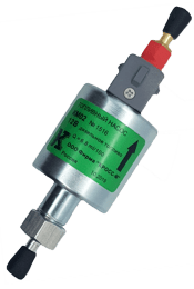
FUEL PUMP MODEL KM02
 |
 |
In March 2012, KROSS-M Firm LLC began production of impulse fuel pumps of the KM02 flow type with a 12-volt solenoid valve with a semi-hermetic contact for starting liquid heaters.
The performance of KM02 pumps is similar to that of KM01 pumps: from 0.4 to 2.5 liters per hour. A distinctive external feature of the KM02 pumps is a green label, which indicates a voltage of 12 volts. By individual order, the pumps can be adjusted to the fuel consumption required by the consumer. Pump weight - 370 grams. Warranty period of operation - 12 months. Non-failure resource at the correct operation not less than 20 million cycles. The pumps have been successfully tested at -55°C.
FUEL PUMPS KM07W, KM08W and KM15W
 |
KROSS-M Firm LLC has started production of KM07W and KM08W fuel pulse pumps for Webasto (Webasto), Pramotronik heaters, an analogue of the pump DP30 and DP42. The pumps are available in 12 and 24 volts with semi-hermetic contact. A distinctive feature of the pumps is a dark red label with the letter W after the pump model, the first letter from Webasto. The electrical connector of the KM07W and KM08W pumps corresponds to the connector of German pumps, so they can be connected to the electrical circuit of German heaters without any alteration. Pump weight - 370 grams. Warranty period of operation of products - 12 months. Non-failure resource at the correct operation not less than 20 million cycles. The pumps have been successfully tested at -55°C.
Samples of labels for KM07W and KM08W pumps:
OOO Firma KROSS-M started production of Eberspacher (Eberspacher) fuel impulse pumps for heaters and heaters with fuel supply (gasoline/diesel fuel) from 0.3 to 1.2 liters per hour. The pumps are available in 12 and 24 volts with semi-hermetic contact. A distinctive feature of the pumps is a gold-colored label with the letter E after the pump model, the first letter from the spelling of the Eberspacher company. The outlet fitting of the pumps is made with a diameter of 5 mm and exactly matches the German models. The electrical connector of the pumps corresponds to the connector of German pumps, so they can be connected to the electrical circuit of German heaters / heaters without any alteration. The weight of one pump is 310 and 370 grams. Warranty period of operation of products - 12 months. Non-failure resource at the correct operation not less than 20 million cycles. The pumps have been successfully tested at -55°C.
Sample labels for pumps:
Fuel filter - 55 rubles.
Suction fitting with polyurethane gasket for Eberspacher pumps - 155 rubles.
Connecting block - 70 rubles.
Prices are inclusive of VAT
PACKAGING AND DELIVERY
When packing, the pumps are placed in an individual gripper bag and a cardboard box, after which they are stacked 20 pieces into a large cardboard box. This double packaging is an additional guarantee of protecting the pumps from mechanical damage during their movement and transportation to their destination.
 |
 |
 |
 |
Delivery of products to the destination is carried out both by self-pickup and with the help of a transport company convenient for the client. We ship products by such transport companies as: "AUTOTRADING", "DEVELIE LINII", "BAIKAL SERVICE", "PEK", "KIT", "ZhelDorEkspeditsiya", which must be specified when submitting an application for products.
The diaphragm dosing pump is practically the most popular unit used in industry and everyday life, as it is highly practical and efficient. Among the main advantages it is worth mentioning compactness, adjustable performance, as well as high accuracy of liquid dosing. This was achieved thanks to a special design. Such a device will easily help to pump the required volume of water in a certain time.
From this article you will learn:
What is the working principle of a diaphragm dosing pump
What are the advantages and disadvantages of diaphragm dosing pumps
How a diaphragm dosing pump is used
How to Evaluate the Efficiency of a Diaphragm Dosing Pump
How to choose a diaphragm dosing pump
Where to buy a diaphragm dosing pump
Diaphragm metering pump: principle of operation

All models of diaphragm dosing pumps can be conditionally divided into two parts: analog and digital. Each of them is also divided into constant and proportional dosing pumps.
It is also important to understand that there are four series of devices in terms of performance: 600, 603, 800, 803. All options presented on the portal are made from PVDF and with ceramic ball valves, which guarantees stable operation of the system with almost all chemical solutions.
our company Biokit offers a wide range of reverse osmosis systems, water filters and other equipment capable of restoring tap water to its natural characteristics.
Our specialists are ready to help you:
connect the filtration system yourself;
understand the process of choosing water filters;
select replacement materials;
troubleshoot or solve problems with the involvement of specialist installers;
find answers to your questions over the phone.
Entrust water purification systems from Biokit - let your family be healthy!
The owners of the patent RU 2307958:
The invention is intended for use in self-contained gas-generating cogeneration plants - mini-CHP, systems of pulsed sprinkling for irrigation of farmland or fire extinguishing, hydropercussion dispersers of solid and liquid substances. SUBSTANCE: impulse jet pump contains a pipeline, lower and upper pressure tanks, between which a combustion chamber is installed, equipped with inlet and outlet valves, a spark plug. The pump is equipped with a nozzle for ejection of water and a shock valve installed between the combustion chamber and the upper pressure tank, blocking the inlet to the upper pressure tank, and a valve consisting of a movable needle-rod located in the nozzle and fixed on a piston connected to a spring. Increases the rate of water ejection. 1 ill.
The present invention is intended for use in self-contained gas-generating cogeneration plants - mini-CHP, pulsed sprinkling systems for irrigation of farmland or fire extinguishing, hydropercussion dispersers of solid and liquid substances, etc.
Known pulse sprinkling apparatus, consisting of a barrel and a nozzle with a hole. A water-air tank is placed on the side surface of the barrel, in the upper part of which an ignition device is installed. Inside the barrel there is a locking body made in the form of a piston and a valve. The upper part of the water-air tank is connected to the completely under-piston barrel, communicated with the atmosphere through a check valve (see A.S. No. 501718, class A01G 25/00, B05B 1/08, published 05.02.76, Bull. No. 5). After ignition of the combustible mixture in the tank under the pressure of expanding gases, the piston moves and the valve opens the nozzle hole, from which a portion of water and exhaust gases are ejected.
The disadvantage of the impulse sprinkler is the need to install an additional energy source to achieve the required degree of compression of the combustible mixture in the tank, as well as a special distribution system to control the inlet valves.
The closest device adopted as a prototype is the Humphrey pump, which is a four-stroke internal combustion engine in which a moving column of water plays the role of a piston. After ignition of the mixture of generator gas with air in the combustion chamber, the water column is set in reciprocating motion within the system lower tank - combustion chamber - upper (pressure) tank, each time carrying a new portion of water from the lower to the upper pressure tank (Technical Encyclopedia , v.14 M.: OGIZ RSFSR, 1931, p.331-332).
The disadvantage of the Humphrey pump is a relatively narrow area of use: lifting large masses of water to a small height. The Humphrey pump, being an efficient converter of the energy of fuel combustion, mainly into the potential energy of rising water, does not contain in its technological chain a converter of this energy into the kinetic energy of pulsed water emissions.
The kinetic energy of a portion of water moving at high speed can be converted into short pulses of high unit power, following one after another. It is these energy sources that can be most in demand in many branches of technology.
Thus, the technical task of the invention is to expand the capabilities of the well-known Humphrey pump: in addition to lifting large masses of water to a small height, the ability to produce a pulsed ejection of a portion of water with high kinetic energy is added, which allows it to be used in various fields of technology: in agriculture for water lifting , irrigation or fire fighting; in the chemical and mining industries for dispersion, crushing of materials; in the energy sector for converting the energy of fuel combustion into the kinetic energy of pulsed liquid emissions for conversion into electrical and other types of energy, etc.
The technical result of the invention is an increase in the speed of the ejection of water, providing short pulsed ejections of water of high unit power, following one after another.
The specified technical result in the implementation of the invention is achieved by the fact that in a well-known pump containing a lower and upper pressure tank, between which a combustion chamber is installed, equipped with inlet and outlet valves, a spark plug, according to the invention, the pump is equipped with a nozzle for ejecting water and installed between the combustion chamber and an upper pressure tank with a shock valve blocking the entrance to the upper pressure tank, and a valve consisting of a movable needle-rod located in the nozzle and fixed on a piston connected by a spring.
A distinctive feature of the claimed device is the presence of new structural elements, namely the additional installation of a shock valve at the inlet of the upper pressure tank, and a valve consisting of a movable needle-rod located between the combustion chamber and the upper pressure tank. These valves form a hydropercussion system that provides powerful pulsed cyclically repeated bursts of water from the valve nozzle with a movable needle-rod, while the emission power can reach up to hundreds of kW, depending on the closing speed of the shock valve.
During operation of the device with the shock valve open, the liquid is directed through it to the upper pressure tank at a speed increasing with time, and at the moment when the pressure force of the fluid on the shock valve exceeds its weight, it rises and closes the hole to the upper pressure tank. In this case, hydraulic shock occurs and pressure increases in the pipeline and on the surface of the valve piston, as a result of which the needle-rod that covers the nozzle rises and the fluid, accelerated by hydraulic shock, is ejected at high speed from the valve nozzle. Thus, it is thanks to the installation of the above valves, which are a hydraulic shock system that converts the kinetic energy of a moving fluid into the energy of a hydraulic shock due to the rapid closing of the shock valve, it became possible to increase the rate of water ejection by impulses, giving short impulse ejections of water of large unit power, following each other. after each other with great frequency.
The analysis of the level of technology carried out by the applicant, including a search through patent and scientific and technical sources of information, and the identification of sources containing information about analogues of the claimed invention, made it possible to establish that the applicant did not find an analogue characterized by features identical to all essential features of the claimed invention. The definition from the list of identified analogues of the prototype, as the analogue closest in terms of the totality of features, made it possible to establish a set of distinctive features in the claimed device that are essential in relation to the technical result perceived by the applicant and are set forth in the claims.
The claimed invention is illustrated in the drawing, which schematically shows an impulse jet pump, general view.
The impulse jet pump consists of a lower 1 and an upper pressure tank 2, between which a combustion chamber 3 is installed, equipped with outlet 4 and inlet 5 valves, and a spark plug 6. A shock valve 7 is installed between chamber 3 and tank 2, blocking the entrance to pressure tank 2 , and a valve 8, consisting of a movable needle-rod 9 located in the nozzle 10 for ejection of water and fixed on the piston 11, connected by a spring 12. The pump also contains a pipeline 13 and an inlet valve 14 for water.
The proposed device - pulse jet pump - operates as follows.
The principle of operation of the inventive impulse jet pump is similar to a four-stroke internal combustion engine, and the role of the piston is played by a reciprocating column of liquid. In the event of an explosion of a mixture of combustible gas produced by a gas generator installation using wood and other waste, coal or any other fuel, and air in combustion chamber 3, the burnt gases expand and move the water column through pipeline 13 and percussion valve 7 towards the upper pressure tank 2 until the exhaust valve 4 opens, through which the exhaust gases exit. When the exhaust valve 4 is opened, the purge valve opens and the combustion chamber 3 is filled with fresh air. When water moves towards the upper pressure tank 2, an additional expansion of gases is obtained, the pressure becomes less than atmospheric, and water is sucked in through the inlet valve 14. The incoming water partly follows the moving column of liquid, partly fills the combustion chamber 3.
When the shock valve 7 is open, the liquid is accelerated towards the upper pressure tank 2 at a rate that increases with time. At a certain speed, the pressure force on the shock valve 7 increases so much that it exceeds its weight. In this case, the shock valve 7 rises under the force of the liquid pressure and closes the hole in the upper pressure tank 2.
During the lifting of the shock valve 7, a water hammer occurs and the pressure in the pipeline 13 increases. Despite the fact that the shock valve 7 did not have time to close completely, the pressure in the pipeline 13 and on the platform of the piston 11 of the valve 8 reaches a value exceeding the compression force of the spring 12. As a result, the needle-rod 9, which covers the nozzle 10, is thrown back and the water, accelerated by hydraulic shock, is ejected from the nozzle 10 at high speed. 2 is opened due to the weight (lowering) of the shock valve 7 and the water column begins to reverse movement. With the reverse movement of water, the removal of burnt gases continues until the water reaches the exhaust valve 4 and closes it, after which the fresh air is compressed in that part of the combustion chamber 3, which is located above the exhaust valve 4. The pressure of the compressed air in this case reaches the value more than the static pressure corresponding to the height of the upper pressure tank 2, so the water column begins to move towards the upper pressure tank 2, accompanied by repeated water hammer, described above.
When the water level in the combustion chamber 3 reaches the exhaust valve 4, the pressure in the combustion chamber 3 will obviously be equal to atmospheric pressure, and with further movement, a rarefaction occurs again, the intake valve 5 opens, and the mixture of gas and air fills the combustion chamber 3. Repeated reverse movement of the water column compresses the working mixture, after which the latter is ignited and a new working cycle begins.
The proposed device in comparison with the known has the following advantages:
There is no additional source of energy to achieve the required degree of compression of the combustible mixture in the combustion chamber;
There is no special distribution system to control the intake valve;
Possibility of obtaining short impulse water bursts of large unit power.
Pulse jet pump containing a pipeline, lower and upper pressure tanks, between which a combustion chamber is installed, equipped with inlet and outlet valves, a spark plug, characterized in that the pump is equipped with a nozzle for ejecting water and a shock valve installed between the combustion chamber and the upper pressure tank, blocking the entrance to the upper pressure tank, and a valve consisting of a movable needle-rod located in the nozzle and fixed on a piston connected to a spring.
Dosing pumps are becoming increasingly popular in both home and industrial automation systems. Such pumps are widely used in fuel supply systems, and in drip irrigation systems and for supplying certain doses of the necessary reagents to tanks. However, industrial products are often of imported origin and are characterized by high cost. We will try to offer a solution that will turn an ordinary pump into a dosing pump.
In the case of using a DC motor as a drive for a dosing pump, the pump performance can be controlled by changing the supply voltage. However, in order to, say, reduce the performance of a pump, it is unsafe to reduce the voltage to low values, because. the engine may move out of the stable control zone. The way out in such a situation may be to provide a pulsed power supply mode for the pump. With each pulse, the engine, as it were, starts to work anew, overcoming the moments of resistance associated with the starting modes (dry friction, speed gain, etc.). .
Quite simply, a pulsed power supply is implemented on standard logic microcircuits. In this scheme, to set the pulse power mode, a generator with a variable pause between power supply pulses is used. Indeed, after all, the power pulse should not decrease to zero in order to guarantee the operating time in the pulse is the minimum necessary for stable operation. The pump cycle time is set using resistor R2. Pause time - resistors R1 and R3
Diode VD3 is used to recuperate the current caused by the self-induction EMF of the motor winding after a break in the power supply through the motor winding. Its purpose here is no different from diodes connected in parallel with the windings of a DC relay to eliminate voltage surges. The VT2 transistor switch is able to provide switching loads with current consumption up to 9 A. Photo of the working layout of the device:

List of radio elements
| Designation | Type | Denomination | Quantity | Note | Score | My notepad |
|---|---|---|---|---|---|---|
| U | Valve | CD4093B | 1 | To notepad | ||
| VT1 | bipolar transistor | BC547C | 1 | To notepad | ||
| VT2 | MOSFET transistor | IRF630A | 1 | To notepad | ||
| VD1-VD2 | rectifier diode | 1N4148 | 2 | To notepad | ||
| VD3 | rectifier diode | 1N4007 | 1 | To notepad | ||
| LD1 | Light-emitting diode | AL307A | 1 | To notepad | ||
| VD4 | zener diode | KS210B | 1 | To notepad | ||
| R1 | Variable resistor | 100 kOhm | 1 | SPO | To notepad | |
| R2 | Resistor | 36 kOhm | 1 | To notepad | ||
| R3 | Resistor | 110 kOhm | 1 | To notepad | ||
| R4 | Resistor | 200 ohm | 1 | To notepad | ||
| R5 | Resistor | 11 kOhm | 1 | To notepad | ||
| R6 | Resistor |
Pulse dosing pumps are called so because of the nuances of their principle of operation: one of the key roles in the operation of such pumps is played by short electrical impulses supplied to the pump drive.
impulsive nature
On our website, there are impulse dosing pumps of the diaphragm (diaphragm) type, also called solenoid pumps. The principle of their operation is as follows: the membrane, bending in one direction or another, increases or decreases the volume of the working chamber of the pump. Accordingly, the chamber is alternately underpressure or overpressure, the liquid is sucked into the chamber or pushed out of it.
The pulsation of the membrane is determined by the reciprocating movements of the pusher, which moves freely inside the solenoid coil. When an electrical impulse is applied to the coil terminals, a magnetic field arises in it, which directs the pusher towards the membrane - the "ejecting" action of the pump is practiced. After the end of the pulse, the magnetic field disappears; the reverse stroke of the pusher is provided by the spring element of the pump mechanism - the working chamber is filled.
scrupulousness
Dosing accuracy is determined by several factors:
- the size of the working chamber;
- the amount by which the membrane is bent;
- the number of membrane pulsations (pump cycles) produced during dosing.
The last parameter - the number of cycles - coincides with the number of pulses applied to the inductor. Technical manuals for solenoid pumps usually list the so-called "pulse volume" in milliliters. Knowing the volume of an individual pulse and the frequency of their supply, you can easily calculate the dosing time.
For example, with a pulse volume of 0.14 ml and a frequency of 120 pulses per minute (pumps of the PKX series, type 01-05), to dispense 420 milliliters,
420 ml / (0.14 ml/imp * 120 imp/min) = 25 minutes.
However, the volume of the impulse can be variable: for example, the pumps of the DLX series have an optional installation of a back cover with a special adjustment knob, with which you can adjust the amount of stroke of the pusher - respectively, the bending of the membrane and the volume of the impulse. In this case, it is better to adjust the dosing taking into account the readings of the external flow meter.
General leadership
The time and volume of dosing for different models of impulse dosing pumps can be adjusted in different ways. The most affordable models have only one option - manual analog or digital adjustment. More "advanced" models support working with an external level sensor or a pulse flow meter. The most complex ones (BT series pump, model PH-RX-CL/M; DLX-PH-RX-CL/M pump, etc.) are equipped with an integrated controller capable of processing signals from sensors of level, flow, acidity, redox potential, chlorine content, temperature. These pumps are essentially compact dosing stations that can be used to solve individual or complex tasks - for example, water treatment or the supply of laboratory reagents.
Dosing systems can also be created using simple models - based on external modular controllers; also such systems are offered in the form of ready-made assembled solutions.
Performance
Impulse dosing pumps are the most common type of pump for dosing relatively small, up to 20 liters per hour, volumes of liquid chemicals. If you need to supply more significant volumes, you can pay attention to the peristaltic pump of the BH3-V PER series (maximum productivity - 100 liters per hour) or industrial diaphragm and plunger pumps (up to 535 and 1027 l / h, respectively).
Detailed information about all the listed series and models of pumps, with detailed technical specifications, application examples and related data can be found in special sections of the site or requested from an online consultant.