He put the metal tile not in the castle. Joints of various elements on a metal tile. Rules for the construction of the truss system
21.11.2011, 15:48
Good afternoon everyone!
I'll duplicate from their home.
Roofers are about to finish the roof, but there is one small BUT. When you go behind the house on the right, you can clearly see the joints of the sheets.
When you look straight ahead or to the left, the joints are absolutely invisible and everything seems to be fine. On the other side of the house, the situation is similar, only the joints are less visible.
Then I took a closer look at other houses covered with metal tiles - similarly (in some places the joints are even more visible).
Attention questions:
1. Who is to blame and what to do?
2. Is it critical - will water swim in, blow out snow? There were a lot of sheets, we decided not to cut them, but to slip them sometimes into 2 waves, sometimes into 3.
3. In general, was it possible to make sure that the joints were not visible (as I said, it is similar on other houses).
Drawings are attached. The joints are circled in red.
Thanks in advance.
21.11.2011, 19:12
I don't think we have that.
21.11.2011, 19:48
fasten the MCH sheets along the edges immediately through two sheets ...
How are you with the wind rose????
you can rivet the joints with colored rivets ...
21.11.2011, 19:53
sanyok, maybe I didn't understand you a little. How is it to fasten along the edges immediately through 2 sheets? So, that's how it sticks...
21.11.2011, 19:56
where is the MC made?
21.11.2011, 20:03
sanyok meant to fasten two sheets at once to each other along the side fly fishing.
More questions:
1) sheet length
2) how to lift
3) the same question as sanyok - who is the manufacturer
4) metal thickness
Well, for a snack - they did such an overlap in vain - the edge of the tile and the previous "longitudinal strip" are not exactly the same profile.
21.11.2011, 20:07
most likely domestic MCH ...
in high-quality production, the length and thickness of the sheet does not matter .... this is our mentality .. the shorter and thicker - the better)))
transportation and lifting does not play a role on a normal MCH .. YATD ....
..or all sheets from different batches (rolling machines)
21.11.2011, 20:13
1. The length of the sheets - there is a party (which is closer to the ridge) 3 meters, which lies below - 4 meters.
2. Raised with handles along the parapet. I mean 2 knocked down pairs of boards, supported on a rafter. The leaf is placed at the bottom, tied with a rope somewhere in the middle and dragged along this tree.
3. Metal profile, metal - they speak Swedish.
4. Thickness 0.5mm, matte "Viking".
Sanyok had in mind to fasten two sheets at once to each other along the side fly fishing.
Can you show it schematically, otherwise I don't quite understand.
PS. apparently, roofers will learn to fly from the roof ....
21.11.2011, 20:24
I disagree (partially).
1) well, I won’t immediately comment on “from different camps”.
2) the thickness of the sheet is important when unloading and lifting - as I saw with customers - no one wore the sheets vertically, but more horizontally, and their playful handles were placed anywhere, and not at least on the steps of the tiles.
3) the length of the sheet matters. I'll explain why. The length of the rolled sheet is measured by a roller, and not even rubberized, but simply rough at the stage between the longitudinal forming by the shafts and the transverse forming by the stamp. The roller is connected to a "figure" that generates impulses, the number of which indicates the length of the interval. The error of this sensor is RELATIVE, and one-sided due to the slippage of the roller. And according to all theories of measurements, the longer the length, the greater the error in ABSOLUTE values. Therefore, with a large length of the sheet, an accumulation of errors takes place.
4) another reason for such a disaster is possible, but this is extremely rare. This is the non-rectangularity of the tile sheet, it is checked simply by measuring the diagonals. Such trouble happens either with deviations in the geometric dimensions of the raw material (for example, the sheet is ALREADY, and when forming with shafts it tries to shift, the first sign is a small "accordion" or "herringbone" along one of the edges of the sheet), or when the mill is not tuned.
21.11.2011, 20:26
They got ahead. Then it is not entirely clear what is the reason. The thickness is normal, the sheets are not long, they lifted normally. HZ, why is that!
21.11.2011, 20:26
something like this.. schematically..
21.11.2011, 20:29
Eugene, Concerning the 4th point - how to understand that this is exactly my case? It seems like the junction line is the same along the entire slope ...
And how in general should the sheets be lifted so as not to cause injury to him?
Pavel, yes, I am also sure that since I should not have. I really want to know who is to blame.
21.11.2011, 20:30
something like this.. schematically..
Yes, that's how I have it.
21.11.2011, 20:31
21.11.2011, 20:35
maybe ... the screws were squeezed .... the edges reared up ....
Hmm ... chtol happens everywhere ... And by the way, how do you know if they have pinched the screw and in general - is there such a thing? Then is there a limitation - with what force it is necessary to clamp the frosts ...
21.11.2011, 20:37
until the rubber band breaks...
21.11.2011, 20:39
Approximately so on the side fly fishing
21.11.2011, 20:43
On the 4th point, no way. Only before installation, on the ground. Dee and this is hardly the case, more like "crazy hands". YATD (s)
21.11.2011, 20:45
IMHO, normal
You can't see it against the light, but you can see it against it.
even wallpaper when glued with an overlap against the light will show you the joint
And then there's the metal...
I also have seams on one side. I did it myself. I didn’t pinch anything.
although maybe this is the only way the Belarusian martyr shows himself? ..
To "calm down" you can clamor at the roofers. Spoil yourself and the builders in the mood.
but it probably won’t be possible to redo something better than it is
Maybe the photo certainly does not quite convey the horror. but no holes seem to be visible.
a month will pass and you won’t even look at the roof if it doesn’t leak. and because of this overlap, it will not flow 100%.
there would be no other problems, but this is a trifle.
Mch "metalprofile" did?
21.11.2011, 20:47
Is there access to the connected MCH from the attic?
or sewn in there?
21.11.2011, 20:54
sanyok, what will it give? After all, the joint from the inside looks like in my cutaway picture. There is not a tight fit at all (from the inside).
21.11.2011, 20:55
put sealant into the seam there ....
the problem is that it doesn’t drip on your head ...
21.11.2011, 21:03
Yes, it hardly drips there. And if a little, then the waterproofing film will delay. So if the appearance is not embarrassing (and he will not be embarrassing in six months), nothing is fatal.
21.11.2011, 21:05
21.11.2011, 21:20
I noticed. What can really excite:
VeloKril, on the roof of the house, check the most obscure place - the junction with ventilation pipes,
which (probably due to some kind of strong knowledge) the architect planned 1 meter below the ridge and parallel! skate
Here the jambs are very convenient to make for builders.
because from above (from the ridge) leakage down the pipe is possible
Check these places very thoroughly with the builders. or without them.
21.11.2011, 21:44
Moreover, either I don’t see the adjunctions, or there really aren’t any. In my opinion, something is wrong! Or the builders are going to install them later (but this is such a hemorrhoid - to put them under the tiles from behind and bring them out on the sides ON it).
21.11.2011, 22:06
Damn, I've written about this so many times!
If vertical lines are visible along the seams, the locks are stretched and not set properly. Stretched, they can be both in length (if the sheet was taken and transferred in a horizontal plane, it bent and the metal straightened a little. Or they took it when carrying and unloading not by the left lock, but by the upper right edge of the sheet.
Not planted - this means that stretched locks will never sit one to one on two adjacent sheets. And they will not repeat the common edge together. That is, the upper edge will not lie on the lower one as if poured in shape.
You can’t fix it with anything. Only if you order new sheets and do everything from scratch.
And if you still managed to overlap the wave more, then this is generally pipets! (if I understood your installation process correctly).
Nothing should leak if the roof slope is at least 15 degrees (this is the limit for any metal tile). But if there are very huge cracks (not visible in the photo), then dirt, dust and snow can end up in the cracks over time. Depending on what kind of landscape you have you in the area.
Screws will not bend like that in any way. They can be pushed through, then it will glare and puff a little, but obviously not like that.
Well, you got the masters! Excuse me...))))
Do you know why now the brigades do not really like to make roofs for the MCH? Because metal at all stages requires accuracy and time. With other roofs it will be easier in everyday life.)))
It is necessary, I look, to open a separate topic about the MCH. I can describe everything in detail. I would like to learn how to draw here ((((. Where to fasten the screws, it’s not necessary to look at the side view of the drawing, but the view of the sheet from above. There are strictly defined points. If you move a little, or take the wrong step -that's it, glare will be provided.)))
And especially I could write about all the junctions - like around pipes, walls, etc. The most important thing is a strict sequence of work. There is a little hint (guess??))): the height of the MCH wave is considered to be 36-38 mm, that is, roughly 4 cm. attach immediately at the right distance from the crate. And then just slip the sheet and ... Well, okay, maybe there will be time, and I will ripen to describe everything in detail separately))
And the pipes always need to be completely sheathed from the very beginning, and only then do the MCH. And now they’ll just crush the entire roof until they finish everything. What a horror! There is also a pipe on the slope. Well, there will be a lot of fences! Killed just by such masters.))))
Or the owner himself did not purchase a profile, corners, an umbrella cap, etc. , and the installation of the MCH has already begun.
21.11.2011, 22:19
Oska, whatever you want, but you need to write now....
21.11.2011, 22:24
Sanyok, this is a long time. Now I can’t. If only to answer a specific question, if they ask quickly))
21.11.2011, 22:27
At the pipe on this house, first, the lower junctions should have been made, then a vertical shift of 4 cm upwards - the upper junctions, then the entire lining, and only then the installation of the MCH.
Here the entire roof needs to be redone. Otherwise, it will definitely flow through the pipe!
From the pipe, from its upper edge along the slope, from below, under the MCH, there should have been a whole "tie" of the lower junction. And now that's it! The crowbar has passed!)))
In general, the complete dismantling of everything, and from the very beginning, but correctly.
21.11.2011, 22:42
Maybe someone will come in handy. Once upon a time I did a compilation from different sources ...
21.11.2011, 22:48
21.11.2011, 22:50
There are inaccuracies. And it is written very superficially. This is an ordinary instruction, as in a booklet from Metalprofile. So to speak, without details and subtleties. But still, some points are voiced, at least.))))
21.11.2011, 22:51
VeloKril, about galvanizing in more detail. How did you make it to the pipe, what shape. And about the bottom apron, please write what you have done there.))) Maybe you will still break through))
21.11.2011, 22:52
Well, to be honest, I thought that after the roof it was possible to make pipe sheathing. Sheets unloaded themselves, horizontally. I didn't know locks could stretch like that. It can be seen that I myself will learn to fly from the roof.
At the expense of pipes - first there was a film, then a counter-lattice, then a crate, then a galvanized sheet 2.2 by 1.1 somewhere (about 3 square meters), then a lower apron, then a tile, then an upper apron, then there will be pipe sheathing.
Thanks everyone for the replies. Oska was especially pleased :). Until her last answer, there was still optimism :).
We just didn’t want to upset you right away ... you never know ..))))))
21.11.2011, 23:07
Looking closely at the pictures, it is clear that there is something around the pipes from below. What kind of apron is there and what shape is the extension for the apron?
21.11.2011, 23:10
Oska, there are inaccuracies, I know, I even know one for sure, but I don’t know how to redraw the drawing. Of course, this is in a nutshell "instruction", for a general idea, in order to more emphasize the difference between slate and MCH. But there is a tie! :da:
Since "such a booze has gone", there is a proposal - but let's write a good instruction, with all the subtleties familiar to forum users. Moreover, it is better in the form of a brochure (in electronic form), and not in the form of answers on the forum, because not everyone can find them. To begin with, you can create a theme, and after a while, compile the brochure into one file. How does such a thought have the right to life, or will we strangle it right away, huh ..?
A metal tile is a material that has already firmly entered our modern and "everyday" construction. It is pragmatic, which means an optimal price-quality ratio. So we can not ignore this topic. So, in this article we will talk in detail about the methods of laying metal tiles, subject to various design features of the roof.
Initially, we will consider the main elements of the roof that we can meet on our building.

| The main elements of the roof P 1 cornice 1.1 Pipe located on a slope, the width of the pipe does not exceed 80 cm: pipe apron |
End points and joins of linear elements 2.1 Beginning or end of the ridge (end of the ridge), cap of the ridge 2.2 The beginning of the ridge, the stub of the ridge 2.3 Toe-in of two skates perpendicular to each other: T-triplets 2.4 Convergence of two ridges and a ridge (top 8 alms) U-tee 2.5 - 2.13 Non-standard roofing units that require professional skills of the craftsman are performed using non-standard elements made to order according to sketches or from a flat sheet in place roof window 3.1 Skylight Penetrations for roof ventilation 4.1 Straight ridge fan Penetrations for engineering networks 5.1 Antenna output Security Devices 6.1 Tubular snow holder |
Now a little about the metal tile itself.
1. General information about metal tiles
 A metal tile is a good example of the transfer of the traditional, centuries-old form of ceramic slot tiles to metal, the use of which on roofs in the form of other forms has also been worked out for centuries. The metal tile combines the aesthetic and functional advantages of traditional tiles with the reliability and durability of modern galvanized steel with a polymer coating.
Visually, the roof consists of a large number of identical "tiles". It is customary to say that across the slope is divided into WAVES, and along - into ROWS, the distance between the rows is usually called STEP.
The waves are formed when the sheet passes through the profiling rolls of the machine, and the rows are formed by stamping.
The working width of the sheet of the most common metal tile is 1100 mm, and this width is made up of 6 waves (the overall width of the sheet of metal is 1180 mm).
For 1 sq. m of surface accounts for 15.6 "tiles" and this goes well with the generally accepted sizes of ceramic tiles.
The step of the most common metal tile is 350 mm, and a row consisting of 6 waves is usually called a MODULE. The length of a single-module sheet is 450 mm, of which:
Approximately 50 mm - the distance from the standard lower cut to the lower stamping line (measured from the cut to the crest of the wave);
350 mm - step, or distance between stamping lines;
Approximately 50 mm - the distance from the upper stamping line to the standard upper cut (measured from the crest of the wave to the cut).
Example: the length of a three-module sheet with regular lower and upper cuts is 1150 mm, a ten-module sheet is 3600 mm, the figure shows a six-module sheet with a length of 2200 mm.
The lower cut is always regular, the upper one can be separated from the upper stamping line not only by 50 mm, but also by 100, 150, 200, 250 or 300 mm when forming a “special order”.
Sheets of metal tiles with regular upper cuts are usually called "warehouse": single-module, three-module, and so on, as a rule, up to ten modules.
Sheets of metal tiles from a "special order" are usually named according to their overall length, for example: sheet 2300 (50+6x350+150), sheet 3750 (50+10x350+200), sheet 6100 (50+17x350+100). The maximum length of a metal tile is usually 6.5-7 m.
A single-module metal tile sheet covers an area of 1 row of 6 waves. Ten-modular - 10 rows of 6 waves, two ten modular - 20 rows of 6 waves when joined in rows or 10 rows of 12 waves when joined in waves.
The roof can be equipped with “stock” sheets of metal tiles or sheets of metal tiles specially made for your roof - “special order”.
When placing an order for metal tiles, “lay out” the sheets of metal tiles on the drawings, taking into account the fact that the joints of the sheets in rows should pass in a single line through the entire slope and intersect with the lines of the joints of the sheets along the waves. At the same time, points of joining four sheets will appear on the slope, which is a standard solution for high-quality metal tiles, during the design of which special measures were provided to compensate for a possible visual accent at the junction of four sheets at one point.
With proper installation of high-quality metal tiles, the joints along the waves and the joints in the rows do not stand out on the common plane of the roof and do not reduce its reliability.
The minimum allowable angle of inclination of the roof is 11 degrees, which corresponds to the ratio of the legs of a right triangle 1:5.
The average consumption of self-tapping screws is 7.5-8 pcs. per 1 sq. m, taking into account the installation of roofing strips.
Metal tiles are supplied with standard roofing strips 2 m long and coated flat steel sheets 1.25x2 m in size, for the manufacture of which the same raw materials were used as for the manufacture of metal tiles.
 Standard roofing strips are usually made for roofs with a slope of 30 degrees. Adjusting these slats for pitched roofs from 10 to 70 degrees is a simple routine operation.
On a special request, roofing strips made according to your drawings can be supplied with metal tiles.
The metal tile is an integral part of the roofing system. When installing the roofing system, special attention should be paid to the organization of under-roof ventilation and waterproofing.
In order to organize under-roof ventilation on the eaves, in some cases, to protect against penetration of birds under the roofing, it is necessary to use a ventilation tape, and on the ridge - to protect against blowing snow - an aeroelement of the ridge.
For waterproofing, it is best to use TYVEK or DELTA waterproofing membranes.
2. Rules for fastening metal tiles
To fasten the metal tile to the crate of the boards, use special roofing screws 4.8x28 mm with an EPDM rubber gasket, painted in the color of the roof.
Adjust the torque limit of the screwdriver so that when the sheet of metal is finally pressed against the crate, the rubber gasket is slightly compressed.
Screw the self-tapping screw perpendicular to the boards of the crate. With a reduced torque of the screwdriver, the compression of the gasket required for sealing will not be achieved.
If the torque of the screwdriver is increased, the gasket will be compressed too much, which can lead to a reduction in the service life of the gasket. In addition, with an increased torque of the screwdriver, there will be a danger of turning the self-tapping screw in the crate and loosening the fastening.
Constantly visually check the degree of compression of the gasket. If a self-tapping screw gets into denser wood, for example, into a knot, with a “regular” screwdriver setting, the self-tapping screw may remain “under-twisted”. Increase the torque limit of the screwdriver, tighten the self-tapping screw and restore the previously set torque limit on the screwdriver.
ATTENTION! Remove the steel chips formed during the tightening of the screws, using, for example, a soft brush.
The main rule for attaching metal tiles to the crate
When fastening sheets of metal tiles along the area of the slope, twist the frosts into regular places located 10-15 mm below the stamping line in the middle between the crests of adjacent waves. With a correctly mounted step crate, you can safely screw the self-tapping screw into any regular place, since there is guaranteed to be a step crate board under the regular place. The metal lies on this board without a gap, and when the screw is screwed in, the metal tile sheet will be securely pressed against the step crate without deformation of the sheet. At the same time, the self-tapping screws will be almost invisible on the roof, since they are located in the shadow of the "step".
A step crate is a crate of boards of the same size, mounted at equal distances from each other with a step equal to the step of the metal tile. The eaves and ridge boards of the crate can have a different thickness and can be installed outside the general rhythm of the step crate.
ATTENTION! The following four figures show typical errors when attaching a metal tile to a batten.

Rule number 1. Docking sheets of metal on the waves.
The fastening of metal tile sheets to each other along the waves is designed to protect the "slope plane" from the effects of side wind and to give the entire "slope plane" a uniform appearance. Drive the self-tapping screws in each row below the stamping line to any place in the "sector" from the crest of the wave to the outer edge of the top sheet, as shown in the figure.
ATTENTION! To ensure that the longitudinal joints of the sheets do not stand out on the plane of the roof, tighten all the screws of these joints until the sheets are finally attached to the crate.
Rule number 2. Docking sheets of metal tiles in rows. 
Docking of sheets in rows always takes place on the board of the step crate. Screw the screws into regular places in each wave.
The figure shows the places of fastening of the metal tile along the area (main rule) and along the perimeter of the sheets (rules 1-5).
Twist along the area of the slope
self-tapping screws with uniform “breakdown” along the slope, moving, for example, from the eaves to the ridge through the row, twisting the screws in every third wave, with a shift to the left or right by one wave when moving to the next fastened row. 
To protect the roof from the effects of wind load, additionally fix with self-tapping screws:
Sheets of metal tiles between themselves when docking along the waves (rule No. 1);
Sheets of metal tiles between each other when joined in rows (rule No. 2).
Sheets of metal tiles to the crate along the cornice line (rule No. 3);
Sheets of metal tiles to the crate along the ridge line (rule No. 4);
Sheets of metal tiles to the crate along the end lines (rule No. 5).
The total consumption of self-tapping screws is on average 7.5-9 pcs. per sq. m.
Rule number 3. Fastening metal tiles on the eaves.
The most common method of forming a cornice assembly is when the lower regular cut of the metal tile protrudes beyond the edge of the cornice strip by about 50 mm and rainwater enters the gutter directly from the metal tile sheet. The cornice strip serves to protect wooden structural elements from splashes.
In order for the lower wave not to “sink” down, the eaves board must be 10-15 mm thicker than the others. The center-to-center distance from the cornice board to the first board of the step lathing is 250 mm with a board width of 100 mm.
Screw the self-tapping screws along the eaves line 60-70 mm above the stamping line in every second wave.
When using the second method of forming the cornice assembly, the regular cut of the metal tile is located on top of the cornice strip and rainwater enters the drain from the cornice strip.
This method can be useful for finding a way out of difficult situations, for example, when installing metal tiles with a stepped cornice and unsuccessful step sizes, or when the roof geometry is broken.

Rule number 4. Fastening metal tiles when approaching the ridge.
 When installing the roof with "warehouse" sheets, the top board of the step lathing will be the supporting board of the ridge. In most cases, you will need to mount an additional ridge board above the top board of the step batten, while ensuring a gap between the ridge boards of adjacent slopes of at least 80 mm to ensure under-roof ventilation.
In order to make it possible to bring the ridge strip at the ends of the house over the end strips, mount a ridge support board with a thickness increased by 10-15 mm. If you mount a ridge board of normal thickness, the ridge will “sag” down relative to the end plank line.
Fastening the ridge strip to the metal tile.
To fix the ridge (spine) plank, tighten it with self-tapping screws to the highest points of the metal tile sheets. Since these points are located at the same distance from the crate, the ridge bar will not deform when the screws are tightened to the nominal compression of the gasket. The distance between the screws should not exceed 0.8 m.
Rule number 5. Fastening of metal tiles on the ends of the slope.
Screw the screws along the end lines of the slope into regular (corresponding to the main rule) places of the metal tile in each wave.
End plate fastening
To fix the end strip, tighten it with self-tapping screws to the highest points of the metal tile sheets in every second wave.
Since these points are located at the same distance from the crate, the end plate will not deform when the screws are tightened to the nominal compression of the gasket.
In addition, attach the end plank to the gable board with self-tapping screws in increments of no more than 0.8 m. Since these screws will be clearly visible, screw the screws in accordance with the markings in order to maintain the rhythm.

3. Rules for handling metal tiles
 ATTENTION! When working with sheets of metal, use gloves.
ATTENTION! Sheets of metal tiles should be taken by the edges of the stamping lines on the sides of the sheets. The application of forces at a point between the edges of the stamping lines on the sides of the sheet can lead to irreversible deformation of the sheet at the points of application of the forces.
Unpack the packs and lay out the metal tiles in accordance with the "layout" of the sheets into separate piles for each slope when working with a "special order" or into separate piles according to the size of the sheets when working with measured sheets. To safely lift the sheets to the roof, mount the “guides” from the boards from the level of the blind area to the level of the eaves.
ATTENTION! From the moment of unpacking a pack of sheets of metal tiles to the moment of fixing the sheets on the roof, there is a danger of uncontrolled movements of sheets under the influence of wind gusts.
Take precautions when storing and moving sheets of metal.
ATTENTION! Before going out on the roof, make sure that the method of insurance you have chosen is correct.
A high-quality metal tile does not deform when a person moves along the sheets in shoes with soft soles, subject to the following rules:
The leg should always be on only one "tile";
The foot should always be parallel to the slope line;
You can only step into the deflection of the wave with the transfer of weight to the toe.
ATTENTION! Don't step on the crest of the wave. Even a roofer weighing less than 50 kg will crush a sheet of quality metal if he steps on the crest of a wave at a point between the stamping lines.
4. Rules for cutting metal tiles
ATTENTION! It is forbidden to cut the metal tile with an abrasive disc ("grinder").
The fact of cutting a metal tile with an abrasive disc (“grinder”) automatically leads to the removal of the quality guarantee of the protective coating of the metal tile.
Use electric nibblers or good metal shears to cut metal tiles.
ATTENTION! Before cutting, put on protective gloves and goggles.
It is most convenient to work with electric nibblers - they can cut metal tiles both on roofs and on the site. The cut structure is the same as when cutting with scissors.
When cutting thin-sheet galvanized steel with shears for metal, the cut structure is such that zinc is transferred mechanically from the outer surface to most of the cut from the outer surface during the cutting process, and zinc is transferred to the remaining part of the cut over time due to the “cathodic protection” effect.
Cutting a metal tile with scissors is more difficult than cutting a flat sheet with scissors. It is necessary to choose comfortable scissors (it is useful to purchase "right" and "left" scissors) and practice.
At the training stage, and in some cases during the installation of metal tiles, you should step back from the marking line to the “cutting” side by a few centimeters, cut it off “roughly”, and then trim the line.
5. Rules for mounting metal tiles on a simple rectangular slope
 ATTENTION! Before starting work, make sure that the waterproofing is installed in accordance with the rules for waterproofing.
Pay special attention to the eaves of the roof.
The figures show examples of the organization of condensate removal from the waterproofing film on the cornice overhang.
The first figure shows how the waterproofing film is brought to a special condensate drip. In this case, all moisture will be guaranteed to be removed beyond the dimensions of the eaves "box".
The second figure shows how the waterproofing is brought into the eaves "box". In this case, condensate may drip from the slots in the eaves eaves. This case is not applicable with increased requirements for the appearance of the cornice filing or with "stucco cornice".
There is no correct way to bring the waterproofing film into the gutter.
Installation of step crate
With a rafter pitch of 600-900 mm, use a 100x25 mm edged board for the crate. Start with the installation of the eaves board, the cornice line should be straight (check on the "lace") and strictly horizontal. As a cornice board, use a board thickened by 10-15 mm. Mount the first board of the step batten with a step of 250 mm from the cornice board, the rest - with a step of 350 mm, checking the step from the first board of the step batten every 5 rows.
ATTENTION! If you made a mistake with the installation of the cornice board, most likely, you will need to redo the ENTIRE step crate.
Mount the hooks of the drainage system on the eaves board, providing slopes in accordance with the project. Mount the cornice strip on the cornice board over the hooks of the drainage system with an overlap of at least 20 mm on each other, connecting them to each other along the flanging lines or simply overlapping.

 When installing a metal tile, you can move both from left to right and from right to left. When mounting from left to right, the next sheet must be slipped under the one previously fixed on the slope. When mounting from right to left, the next sheet must be superimposed on the previously fixed on the slope. In both cases, to ensure high-quality joining along the waves, first fasten the sheets together with self-tapping screws “roughly” through one or two rows to ensure optimal joining of the sheets with each other, then twist the rest and only after that fix the mounted sheet on the slope.
When joining the sheets of metal tiles in rows on the slope, there will be places where the "four corners" of the sheets of metal tiles are joined together.
The most correct way of positioning the sheets is such that above the two "sheet corners" with capillary grooves there will be two "sheet corners" with a "covering edge". To do this, first join a couple of sheets in rows, and then join a couple of the following sheets to the side of them. Another installation method is also allowed: first mount the bottom sheets joined along the waves, and then mount the top sheets. In this case, there will be a slight thickening of the junction points of the “four corners”.

The reason for this thickening is clear from the figure. To eliminate such a thickening, it is necessary to slightly “straighten” the capillary groove on one of the bottom sheets below the stamping line or cut off a small fragment of the corner, which slightly complicates installation.
When developing the profile of the metal tile, it was not foreseen the possibility of mounting the sheets of the metal tile "split" with spacing relative to each other of the joints in waves and joints in rows.
A large number of joints, indicated in the figure by the number 2, can lead to a "running" of the shift of the stamping lines relative to each other and a violation of the "rectangular ™" of the slope typed from the sheets of metal tiles. In isolated cases, for example, when approaching the edge of a slope or when avoiding obstacles, such a joint of sheets, indicated in the figures by the number 1, is acceptable.
 The figures below show the method of bringing water to the slope from the apron of the roof window. In the left picture, you can see that water from the apron of the roof window flows onto a specially cut bottom sheet.
The right picture shows the next step, the apron of the roof window is covered with a side sheet specially cut to the width, the lower part of which covers the apron of the roof window and reaches the regular joint of the metal tile sheets in rows.
The bottom and side sheets are cut from one sheet of metal tile, and due to the “overlay” of parts of the sheet on top of each other at the exit point of the apron, the total length has decreased by one module. If, when laying out the sheets of metal tiles, the sheet from which the bottom and side sheets were cut was not “extended” by one module, it can be extended with a single-module sheet.
A typical mistake is to “embed” the apron of the roof window into a side cut on a sheet of metal, in which a hole will remain on the edge of the cut, on the surface of the slope. Small but a hole.
ATTENTION! If necessary, “embed” a roof window, a pipe (located significantly below the ridge) or a dormer window into the slope, prepare two single-module sheets of metal tiles for each element built into the roof.


With any methods of joining sheets of metal tiles to each other, these sheets will be assembled into a rectangle, which will have equal sides, upper and lower edges, as well as diagonals. The exact correspondence of these dimensions to each other is determined mainly by the quality of profiling. It is impossible to “stretch” in width, to “lengthen”, to turn a “rectangle” assembled from sheets of metal tiles into a “trapezoid” or “rhombus”.
Attempts to "stretch" or "compress" the laying of sheets due to the joint will inevitably lead to visual "protrusion" of the joint lines.
From the correct positioning on the slope of the first sheet depends on how accurately the "rectangle", assembled from sheets of metal tiles, will fall on the slope. Rotate, move, stretch the "rectangle" will not work. When mounting the first sheet, you set the cornice line, both gable lines and the ridge line.
The main line is the cornice line. It is clearly visible and not covered by any slats!
Starting the installation of metal tiles, "aim" at the cornice line. When installing the first 3-4 sheets of the bottom row, carefully fasten the sheets to each other and fasten them minimally to the crate.
If during the check a deviation from the eaves line is found, correct the position of the sheets, fix them and continue mounting the slope. Carry out the final fastening of metal tile sheets in accordance with the previously given Rules.
Installation of end strips


Before installing the end strips, mount the support boards along the lines of the eaves, as shown in the figure. Fasten the end plank to the slope at the points of contact with the tops of the waves in every second wave and from the end to the support board in accordance with the previously made markings. Connect the end strips to each other along the flanging lines or overlay with an overlap of at least 2 cm.
If the width of the slope was not “customized” to the size of the wave of the metal tile, the sheet may approach one of the gables with the lower part of the wave. At the same time, the standard gable bar will not cover the comb. Adjust, if possible, the size of the gable overhang or mount an additional safety roofing strip, made especially for this place. Install, if necessary, a universal seal between the safety roofing strip and the sheet of metal.
Installation of ridge rails

ATTENTION! Make sure that all planned under-roof ventilation measures are implemented.
On gentle slopes, to prevent snow from blowing under the ridge, mount a ridge aero roller between the metal tile and the ridge bar. If the installation of point ridge fans is planned to ensure under-roof ventilation, install a universal seal between the metal tile and the ridge bar.
Start installation from one of the ends, mount the ridge over the end strips, let the edge of the ridge out by 2-3 cm. Attach the parts of the flat ridge to each other with an overlap of at least 10 cm or using tinplate technology. Dock the details of the semicircular ridge with each other along the stamping lines.
At angles of inclination of the roof more than 45 degrees, the location of the ridge board and the method of fastening the ridge significantly depend on the specific value of the angle of inclination of the roof.

At the stage of mounting the battens, model the ridge assembly for your case of combining the angle of the roof and the model of the ridge plank. This is the only reliable way to get a good result or to detect an error in time when ordering a metal tile.
Adjust the angle of the ridge strip to the angle of the roof slope by bending or unbending it along the lines indicated in the figures. Mounting shelves of skates in the "free" state must correspond to the angles of inclination of the slopes.
In most cases, you will need to mount an additional ridge board above the top board of the step batten, while ensuring a gap between the ridge boards of adjacent slopes of at least 80 mm to ensure under-roof ventilation.
The thickness of this board should be 10-15 mm more than the thickness of the boards of the step crate.
At slope angles of more than 45 degrees, the shape of the semicircular ridge will differ from the original.
The standard plastic plug will need to be modified or a steel plug made by you from a flat sheet will need to be mounted.
6. Rules for the installation of metal tiles on trapezoidal and triangular slopes
ATTENTION! Make sure that the waterproofing is working and that it is possible to implement the planned under-roof ventilation measures. In addition to the bars of the counter-batten along the rafters, attach the same bars along the ridges in the plane of the slopes on both sides of the ridges. Mount the cornice board and stepping boards. Form the cornice assembly, including installation of the gutter hooks, condensate drip and cornice strip.
Prepare for installation sheets of metal tiles intended for each slope in accordance with the "layout" of the sheets. As a rule, on the "layout" there are instructions for starting the installation, from one of the edges or from the center line. As with the installation of a rectangular slope, first of all it is necessary to align the bottom sheets along the eaves line (the figure shows an example of starting the installation from the left edge).
Cut sheets of metal tiles along oblique lines along the ridges so that the distance between the cut sheets on adjacent slopes is 60-100 mm.
Mount from the bottom up, placing the joints in rows in a common line in accordance with the layout.
Mount the ridge strips on the ridges from the bottom up. Fit the ridge battens to the angle formed by the slopes. Cut the lower part of the straight ridge according to the angles given by the ridge line. At the bottom of the semicircular ridge, mount the plastic cap of the ridge, having previously fitted it in place.
Make sure that the axis of the ridge bar strictly corresponds to the axis of the ridge. The axis of the ridge is easy to determine for the case of the same angle of inclination of neighboring slopes.
At different angles of inclination of neighboring slopes, it is more difficult to determine the axis of the ridge. Be sure to determine the axis of the ridge and fasten the ridge bars in strict accordance with the axis.
Only in this case you will be able to beautifully join the ridges and the ridge in the upper part. In most cases, the junction of two ridges and a ridge you will beautifully make using a plastic Y-tee. In cases where the Y-tee is not suitable for such a joint, use colored self-adhesive tapes, usually used for junctions when working with cement-sand or ceramic tiles. With good tinsmithing skills, you will make beautiful joints of ridges and skates from a flat sheet using self-tapping screws, rivets and sealant.
7. Rules for the device of valleys

The device of the valley, starting under the line of the ridge and ending at the line of the cornice
ATTENTION! Make sure that the waterproofing along the valley is installed correctly, there are gaps for water and small debris along the valley counter-lattice, there are no tears or mechanical damage to the waterproofing.
Mount in the valley by an additional board between the boards of the step crate. Prepare the required number of valley planks and mount them from the bottom up with an overlap of 200-300 mm. Cut the lower plank of the valley just below the eaves line and make a flanging on it along the eaves line. Install a universal seal along the flanges of the valley strips and under the ridge.
Cut the sheets of metal tiles bordering the valley according to the markup. Sheets should not reach the center line of the valley 60-100 mm on each side. When fastening the cut sheets, it is allowed to screw the self-tapping screws into “regular places” located 10-15 mm below the stamping line in the lower part of the wave through the metal tile sheet and through the valley plank no closer than 250 mm from the valley axis.
In these places, the sheets of metal tiles touch the plane on which the valley planks lie. At the same time, the self-tapping screws that have passed through the metal tile sheet and through the valley plank will firmly press the metal tile sheet to the valley plank at the attachment points with self-tapping screws. When indenting from the "regular places" at the attachment points between the sheet of metal and the valley strip, there will be a gap, which can lead to leaks through the valley strip at the points where self-tapping screws pass through it.
ATTENTION! It is not allowed to tighten self-tapping screws at a distance of less than 250 mm from the axis of the valley. If the project provides for the installation of a decorative lining of the valley, mount it, moving from the bottom up with an overlap of at least 10 cm.
Device of a valley starting on a slope and ending on a slope
ATTENTION! Make sure that the waterproofing along the valley is installed correctly, there are gaps for water and small debris along the valley counter-lattice, there are no tears and mechanical damage to the waterproofing.
Mount in the valley by an additional board between the boards of the step crate. Place the metal tile sheet against the side wall of the dormer window as follows:
Cut the sheet of metal tile adjacent to the side wall of the dormer window along the length so that the line of your cut is at least 200 mm higher than the exit of the valley to the slope (the remaining part of the sheet of metal can be used to continue installation with the addition of a single-module sheet to it in order to exit to a common line of joining sheets in rows);
To bring the sheet to the side and front walls of the dormer window, make cutouts according to the size of the dormer window and mount the metal tile sheet.
On a sheet of metal along the walls of the dormer window, mount a universal seal.
Install the cornice strip on the eaves of the dormer window. Mount the pre-prepared valley strips in the valley. Cut the bottom of the valley plank along the eaves and along the exit line to the slope. If necessary, mold the edge of the valley facing the slope in order to ensure a tight overlap of the valley plank on the metal tile sheet. It is allowed to slightly trim the bottom sheet of the metal tile with a mallet.
When extending the valley, provide an overlap of 200-300 mm, depending on the angle of inclination of the slopes.
In the upper part, join the sheets of the left and right valleys using tinsmith techniques or on self-tapping screws using sealant. The protection of the dormer window ridge line from water ingress from the upper slope depends on the thoroughness of the preparatory work in this place.
Mount a universal seal along the flanges of the valley.
Get ready for the installation of sheets of metal with oblique cuts on a large slope.
If you use the part remaining from the side sheet of the metal tile, bring the lower cut on it to the form of a regular one and add a single-module sheet to it in order to bring the top level of the sheet to the common joining line along the rows on the slope.
Prepare for installation the first sheet of the main slope above the valley. Its lower part must necessarily be below the exit line of the valley to the slope. Place the prepared sheet on the metal tile sheet previously mounted below the valley, with the sheets overlapping at least 200 mm, and the valley sheet will be sandwiched between the mounted and previously mounted sheets. Mount all sheets bordering the valley.
Make sure that the gaps between the cut sheets and the centerline of the valley are 60-100mm.
When fastening the cut sheets, it is allowed to screw the self-tapping screws into “regular places” located 10-15 mm below the stamping line in the lower part of the wave through the metal tile sheet and through the valley plank no closer than 250 mm from the valley axis.
In these places, the sheets of metal tiles touch the plane on which the valley planks lie. At the same time, the self-tapping screws that have passed through the metal tile sheet and through the valley plank will firmly press the metal tile sheet to the valley plank at the attachment points with self-tapping screws.
When indenting from the "regular places" at the attachment points between the sheet of metal and the valley strip, there will be a gap, which can lead to leaks through the valley strip at the points where self-tapping screws pass through it.
ATTENTION! It is not allowed to tighten self-tapping screws at a distance of less than 250 mm from the axis of the valley.
If the project provides for the installation of a decorative lining of the valley, mount it, moving from the bottom up with an overlap of at least 10 cm.
ATTENTION! It is forbidden to mount a sealant between the sheets of metal tiles and the decorative overlay of the valley.
Fix the decorative overlays of the valley to the upper points of the sheets of metal tiles adjacent to it.
ATTENTION! Make sure that the screws securing the valley lining have not damaged the previously installed valley planks.
The overlay of the valley decorates oblique cuts of the metal tile and reduces the likelihood of snow blowing between the sheets of the metal tile and the valley. The water collected from the slopes falls under the valley lining and flows along the valley fold line. Last year's leaves that have fallen on the roof also fall under the valley lining and, with a sufficient gap between the cut edges of the metal tile, will be washed away with water along the valley planks.
ATTENTION! If the house is located in the forest, dismantle the valley lining from time to time and clean the water channel.
8. Rules for avoiding pipes and other obstacles
 Bypassing a pipe located on a slope, the width of the pipe does not exceed 80 cm
When bypassing pipes and other obstacles on the roof, you have to solve two problems:
The first task is to "intercept" the water from the slope above the pipe, "disperse" it to the right and left, "draw" it along the pipe and "release" it onto the slope under the pipe;
The second task is to prevent water from entering the house and bringing it to the roof, descending along the walls of the pipe.
To solve these problems around the pipe, you need:
Manufacture and mount a metal apron, part of which is located in the roof plane and fixed on the roof, and part rises along the pipe 150-200 mm above the roof plane;
Mount the junction bar over the apron and seal the joint between the pipe and the junction bar.
ATTENTION! Make sure the pipe is plastered to the desired height. After installing the apron, the part of the pipe under the apron will become inaccessible. Make sure that the waterproofing is led to the side edges of the pipe, and on the slope above the back edge of the pipe, a drainage groove is built into the waterproofing (no further than 0.8 m from the rear edge of the pipe).

Mount additional batten boards over the rear edge of the pipe at a slope length of approximately 50 cm. Cut the left and right sheets of metal tiles adjacent to the pipe along the length so that your cut lines are above the stamping line, and the distance from the top edge of the pipe to these stamping lines is not less than 150 mm. The remaining parts of the metal tile sheets can be used to continue the installation with the addition of a single-module sheet to them in order to reach the common line of sheet joining in rows.
Mark lines on the side faces of the pipe 150 mm above the plane of the top of the roofing, transfer these lines to the front and rear faces of the pipe, and you will find out the required height of the lower and upper aprons.
Prepare the bottom and side (right and left) parts of the apron. Correctly made details:
They rise to the side face of the pipe by 150 mm;
They enter the slope by at least 200 mm;
The lateral parts of the right and left parts of the apron go beyond the nearest wave crest of the metal tile;
With the lower part, the side parts of the apron reach the bottom of the lower part of the apron;
The upper part of the side parts of the apron go 150-200 mm higher than the back face of the pipe.
Connect the 3 parts of the apron to each other and fix the lower apron to the metal tile with screws.
Use a mallet to straighten the sheets of metal tile in those places where they will be covered by the upper part of the apron. Prepare the top piece of the apron. Properly made apron: - comes to the lower edge of the pipe to the marking line;
On the sides covers the side parts of the apron;
Up the slope it goes 100-200 mm higher than the sheets of metal;
At the top of the slope, it ends with a flanging up.
Connect the top apron with the side apron using tin technology.

If necessary, seal the joints between the parts of the apron. Mount the universal seal in the upper part of the apron.
The top sheets of metal tiles must have a horizontal regular cut in the lower part, and in the upper part - reach the common line of joining along the rows on the slope or to the common line of the ridge.
If you use the parts remaining from the side sheets, bring the lower cuts on them to the form of regular lower cuts and add a single-module sheet to them in order to bring the top level of the sheets to the common joining line along the rows on the slope.
Lay these sheets over the splashback, with the top of the splashback sandwiched between the installed and previously installed sheets.
ATTENTION! A typical mistake is to install the top part of the apron into the cut of the metal tile, as shown in the lower figure, since the cut is located on the water drain line.
To prevent the ingress of water from the side faces of the pipe under the apron, rigidly fasten the junction bar along the perimeter of the pipe over the apron and seal the gap between the junction bar and the side faces of the pipe by laying the sealant in a specially cut groove or in the outer flange of the bar.
Before mounting this junction bar, proceed with a mallet to the upper parts of the flanges to the side faces of the pipe. In some cases, the junction bar can be subsequently covered with plaster.
Bypassing a pipe located on a slope, the width of the pipe does not exceed 80 cm, the distance from the ridge to the rear edge of the pipe does not exceed 1 m
Making an apron in this case is easier than in the previous one, because it is possible to bring the upper part of the apron under the ridge over the sheets of metal instead of embedding this part into the slope between the sheets of metal. Sometimes this technique is also used to bypass pipes located 3-5 meters from the ridge, a flat sheet goes above the pipe directly under the ridge. Reliable, but ugly, since the strip of flat non-profiled sheet above the pipe falls out of the overall picture of the slope.
Bypassing the pipe located in the ridge
This is the simplest case, and the width of the pipe does not matter.
Pay special attention to connecting the side aprons of different slopes to each other and sealing the junction of the skates to the pipe.
Bypassing a pipe or other obstacle located on a slope, the width of the obstacle exceeds 80 cm
This case is more difficult than the previous ones. You will need the skills gained from avoiding pipes less than 80 cm wide, and the skills gained from making slope access valleys.
On top of the slope, make a "decline", guaranteed to take the water to the right and left of the pipe. "Razuklon-ka" consists of two additional slopes, covered with metal tiles, with valleys with access to the slope. If the pipe is not wide, for example, 1.2 m, it makes no sense to cover the slopes of the "decline" with metal tiles, a flat sheet is enough.
Pipe bypass. Cases requiring the work of a professional tinsmith
In the previous sections, only rectangular pipes were considered.
When bypassing a round pipe, the principles of embedding an apron in the roof remain the same as described above. To connect the parts of the apron to the pipe, professional tinsmith skills are required. Modern insulated round pipes made of stainless steel, as a rule, are equipped with a special transitional apron-cap.
Sometimes, due to a misunderstanding, the pipe falls into the valley, onto the flow of water collected from two slopes.
A roofer with good tinkering skills will find a way to reliably carry water even past a pipe in a valley. It is better for novice roofers not to experiment and invite an experienced tinsmith to this area of work, for example, a specialist in seam roofs, or to achieve the transfer of a pipe from a valley.
9. Rules for junctions to walls
Side connection to the wall
 ATTENTION! Make sure that the wall fragment is plastered to the desired height (if necessary for the installation of the junction strips). Make sure that the waterproofing is brought to the wall to the correct height and glued to the wall.
If possible, start the installation of the slopes adjacent to the wall from the side of the wall. In this case, you will start from the factory edge of the sheet and there will be a wave crest under the wall strip.
Before mounting the wall strip, mount a universal sealant on the metal tile sheets. The wall plank must protrude at least 150 mm onto the wall. Attach the wall plank to the metal tile with self-tapping screws (at the upper points of the metal tile combs in contact with the plank).
If the metal tile has approached the wall with an “unsuccessful” phase of the wave and the regular wall plate does not cover the ridge, use an additional lower safety apron or mount a specially made wider wall plate.
Top wall connection device
ATTENTION! Make sure that the wall fragment is plastered to the desired height (if necessary for the installation of the junction strips). Make sure that the waterproofing is brought to the wall to the correct height.
ATTENTION! Make sure that the planned measures for the implementation of the under-roof ventilation project will be implemented during the installation of the top junction.
In most cases, it will be necessary to add an additional board above the last board of the step lathing, and its thickness should be 10-15 mm more than the thickness of the boards of the step lathing. The board and sheets of metal tiles should not reach the wall by 50-80 mm to ensure the functioning of under-roof ventilation. In the case of a small angle of inclination of the slope, in order to prevent snow from blowing in especially critical cases, mount the ridge air element between the metal tile and the wall plank, leading one of the edges of the ridge air element onto the wall.
Carefully unbend the wall plank to the desired angle, cut off excess metal from the upper part, adjust it in length and attach it to the ridges of the metal tile with self-tapping screws. Attach the wall planks to each other with an overlap of at least 10 cm or using tin-plate techniques.
Above the wall plank, mount the junction bar “in the groove” or the junction bar “overlay” and seal the gap between the junction bar and the wall by laying the sealant in a specially cut groove or in the outer flange of the bar.
In some cases, the junction bar can be subsequently covered with plaster. Sometimes you can do without an adjoining strip, for example, in cases where the wall strip will be covered with a sheathing board, siding or external insulation, followed by plastering.
Bypass adjuncts on the wall
To bypass wall ledges, you will need the skills you learned from walking around pipes.
ATTENTION! Make sure there is a “groove” installed in the waterproofing layer that drains water away from the wall and onto the slope away from the ledge.
The figures show two methods. In the upper figure, the "apron" around the ledge is made in the same way as for the pipe located far from the ridge. On the bottom - the upper part of the "apron" is brought to the top of the slope, under the wall plank of the upper junction (or under the ridge bar).
10. Rules for docking roofing strips
In the figure "Example of a roof" at the beginning of the instructions, the numbers from 2.1 to 2.13 indicate the places where various roofing strips join each other.
Serially produced docking and end elements of a semicircular ridge (pos. 2.1-2.4) are applicable for slope angles from 15 to 45 degrees and for crossing slopes with the same slope angles.
The junction of several ridges on the "tent" (2.5), the junction of the ridge and the ridge extending from the ridge (2.8), the transition from the ridge to the junction on the slope of two valleys (2.6), the upper end of the ridge resting against the wall (2.7) as in the case of a semicircular, and in the case of a straight ridge, it requires serious tinsmith skills from the roofer. In some cases, it is possible to apply a self-adhesive sealing tape, matched to the tone of the metal tile.
11. Rules for the installation of skylights
The installation rules for roof windows are detailed in the instructions attached to each roof window, flashing, kit for providing a continuous insulation loop and kit for forming internal window slopes.
Pay attention to the preparation of openings for skylights. Sheets of metal tiles can approach the window opening with a “successful” or “unsuccessful” wave phase and a step phase. It is impossible to move the entire array of metal tiles. The opening of the roof window, as a rule, can be slightly moved up or down in order to ensure a good connection between the lower apron of the roof window and the sheets of metal.
The place of embedding the lower apron of the roof window between the sheets of metal is usually determined only during the installation process, and it is almost impossible to order sheets for installation under the apron and above the apron in advance.
Pre-ordered single-module sheets help out, which allow you to compensate for the loss of one module for inserting an apron between sheets of metal tiles. It is unacceptable to insert the apron of the roof window flashing into the cut of the metal tile sheet.
After installation, do not throw away the instructions, leave the opportunity for the technical supervision employee to verify the correct installation of both skylights and accessories for them when accepting work.
12. Rules for the installation of "pass-through" elements
"Pass-through" elements are indicated in the figure "Example of the roof" by the numbers 4.1-5.3. The installation of the "pass-through" elements is described in detail in the instructions supplied with the supplied element.
After installation, do not throw away the instructions, leave the opportunity for the technical supervision employee to make sure that all the “pass-through” elements are installed in accordance with the instructions when accepting work.
13. Rules for the installation of safety devices
 The installation of safety devices is described in detail in the instructions supplied with the device. The most common and easy to install is a tubular snow retainer.
Mount tubular snow guards above the wall, 2-3 waves above the eaves, fasten to the standard boards of the step crate through the metal tile in accordance with the figure shown. Mount the brackets in every fourth or fifth wave, while the step between the brackets will be 700-950 mm.
The pipes can be connected to each other anywhere between the standard mounted brackets. The free end of the pipes should not be more than 300 mm from the outer bracket.
After installation, do not throw away the instructions, leave the opportunity for the technical supervisor when accepting work to make sure that the safety devices are installed in accordance with the instructions.
Before the final delivery of work on the installation of metal tiles, once again carefully take a look at the roof, at each slope.
1. Visually check the general view of the roof, the appearance of longitudinal and transverse joints when viewed from different sides, the presence of dents, make sure there are no foreign objects on the roof and in the gutters.
2. Make sure that the sheets of metal tiles are fastened with screws to the base and to each other:
Evenly along the slope in regular places in accordance with the main rule;
At the junctions of sheets along the waves (rule No. 1);
At the joints of sheets in rows (rule No. 2);
On the cornice line (rule No. 3);
When approaching the ridge and ridges (rule No. 4);
Along the gables (rule number 5).
Make sure that there are no self-tapping screws in abnormal places.
3. Make sure that the components are fastened securely by visually assessing the number and location of screws, make sure that there are no deformations of the components during installation.
4. Visually check the correct installation of the end and ridge strips, as well as the appearance and reliability of the joints of these strips with each other.
5. Make sure that under-roof ventilation is possible; that the eaves unit is provided with the possibility of air inlet: that in the ridge, ridges, upper junctions to the walls the possibility of air outlet is provided and protection against blowing snow under the roofing through ventilation devices (if necessary) is provided.
6. Check the quality of cuts of metal tiles, make sure that there are no metal shavings on the surface of the sheets, and that there are no scale or other traces on the sheets from cutting any metal or other products on the roof.
7. Make sure that the valley device is correct:
Water from the valley enters the gutter (if the valley ends at the eaves);
The valley plank is brought out between the lower and upper sheet of the metal tile not into the notch of the sheet (in case the valley ends on the slope);
At the point of convergence of two valleys, insurance is provided against the ingress of water and snow under the ridge at the upper junction of the valleys;
Between the overlay of the valley and the metal tile, a natural gap is left for the passage of water to the bottom bar of the valley.
8. Pay attention to pipe bypass aprons:
The top part of the apron should be inserted between the sheets of metal tiles, and not into a cut on the sheet;
The side parts of the apron should cover the wave crest of the metal tile, a sealant should be mounted between the apron and the metal tile;
At the junction of the apron and the pipe along the perimeter of the pipe, a “adjacency bar in the gate” or “adjacency bar in the overlay” should be mounted using a sealant.
9. Check the correctness of the connection to the walls.
10. Make sure that the bottom aprons of the roof windows come to the surface between the sheets of metal, and not into a cut in the sheet of metal.
11. Make sure that snow guards and other safety devices are securely fastened to the roof. Your experience may suggest that changes should be made to the project and snow retainers should be added in a number of places.
12. Take another look at the roof plan, inspect the installed roof and make sure that during the installation of the metal tile, all measures prescribed by the project for organizing ventilation of the under-roof space have been completed. 
How to fasten a metal tile: fastening scheme and installation rules.
It would seem a simple, insignificant step, but in fact, fastening a metal tile is a responsible process that has strict rules, on which not only the neatness of the roof depends, but also its service life, reliability from leaks, and resistance to strong gusty winds.
To fasten the metal tile to the crate of wooden boards, special roofing hexagonal screws 4.8 × 28 mm with a rubber gasket are used, the caps of which correspond to the color of the roof. You can buy them together with metal tiles, and in case of a shortage, you can buy them at the nearest construction market or in a store.
Tool for fastening metal tiles
For fixing metal tiles, use screwdrivers and a hexagonal nozzle for self-tapping screws. In this case, the best option for a screwdriver is cordless. When using electric screwdrivers, metal tiles may be damaged in the form of scratches left by extension cords. It also greatly affects the convenience and speed of installation.
The nozzle for self-tapping screws is used in the size corresponding to the size of the screw head. As a rule, these are nozzles with a magnet.


Fastening of a metal tile
Initially, you need to adjust the torque limit of the screwdriver so that when the sheet of metal is finally pressed against the crate, the rubber gasket is slightly compressed.

You need to tighten the self-tapping screw perpendicular to the boards of the crate. With a reduced torque of the screwdriver, the compression of the gasket required for sealing will not be achieved.
Incorrect screw tightening
With increased torque on the screwdriver, the gasket will be compressed too much, which may result in reduced gasket life.
In addition, with an increased torque of the screwdriver, there will be a danger of turning the self-tapping screw in the crate and loosening the fastening.

During the fastening of the metal tile, the degree of compression of the rubber gasket is constantly visually controlled.
If a self-tapping screw gets into denser wood, for example, into a knot, with the "regular" setting of the screwdriver, the self-tapping screw may turn out to be under-twisted. In such cases, it is necessary to increase the torque limit of the screwdriver and tighten the self-tapping screw. Then restore the previously set torque limit on the screwdriver.
The main rule for attaching metal tiles to the crate
When fastening sheets of metal tiles, along the slope area, the screws are screwed into regular places located 10-15 mm below the stamping line - in the middle between the crests of adjacent waves.

With a correctly mounted step crate, you can safely screw the self-tapping screw into any regular place, since there is guaranteed to be a step crate board under the regular place.

At the same time, the metal lies on this board without a gap, and when the self-tapping screw is tightened, the metal tile sheet will be securely pressed against the crate without deformation of the sheet. At the same time, the self-tapping screws will be almost invisible on the roof, since they are located in the shadow of the "step".
Step crate- this is a crate of boards of the same size, mounted at equal distances from each other with a step equal to the step of the metal tile. The eaves and ridge boards of the batten may have a different thickness and can be installed outside the general rhythm of the step batten.
Incorrect fastening of the metal tile to the crate
The figures below show typical common mistakes when attaching a metal tile to a crate.
Self-tapping screw 5 mm from the edge of the board:

Fastening to the edge of the board leads to the fact that the self-tapping screw splits the edge of the board, which makes the fastening itself extremely unreliable.
The step of the crate is observed, but at the same time the step crate is displaced from its regular places:

When the gasket is pressed, the metal tile sheet is deformed (deformation between the stamping lines):

When the gasket is pressed, the metal tile sheet is deformed (deformation along the stamping line):

Rule number 1. Joining sheets of metal tiles along the waves
The fastening of metal tile sheets to each other along the waves is intended to protect the slope plane from the effects of side wind and to give the entire slope plane a uniform appearance. Drive self-tapping screws in each row below the stamping line to any place in the "sector" from the crest of the wave to the outer edge of the top sheet, as shown in the figure.

In order for the longitudinal joints of the sheets not to stand out on the plane of the roof, tighten all the screws of these joints until the sheets are finally attached to the crate.
Rule number 2. Docking sheets of metal tiles in rows
Docking of sheets in rows always takes place on the board of the step crate. Screw the screws into regular places in each wave.

The figure shows the places of fastening of the metal tile along the area ( main rule) and along the perimeter of the sheets (rules 1-5).
Self-tapping screws are screwed along the area of the slope with a uniform "breakdown" along the slope, moving, for example, from the cornice to the ridge through the row, twisting the screws in every third wave, with a shift to the left or right by one wave when moving to the next fastened row.

To protect the roof from the effects of wind load, it is additionally fixed with self-tapping screws:
- sheets of metal tiles between themselves when docking along the waves (rule No. 1);
- sheets of tiles between themselves when docked in rows (rule No. 2).
- sheets of tiles to the crate along the ridge line (rule No. 4);
- sheets of tiles to the crate along the end lines (rule No. 5).
The total consumption of self-tapping screws is on average 8-10 pieces per 1 m².
Rule number 3. Fastening metal tiles on the eaves
The most common method of forming a cornice unit, in which the lower regular cut of the metal tile protrudes beyond the edge of the cornice strip by about 50 mm, and rainwater enters the gutter directly from the metal tile sheet. The cornice strip serves to protect wooden structural elements from splashes.
In order for the lower wave not to sink down, the cornice board must be 10-15 mm thicker than the others. The center-to-center distance from the cornice board to the first board of the step lathing is 250 mm with a board width of 100 mm.
Self-tapping screws are screwed along the cornice line 60-70 mm above the stamping line in every second wave.
When using the second method of forming the cornice assembly, the regular cut of the metal tile is located on top of the cornice strip and rainwater enters the drain from the cornice strip.
This method can be useful for finding a way out of difficult situations, for example, when installing metal tiles with a stepped cornice and unsuccessful step sizes, or when the roof geometry is broken.
Rule number 4. Fastening metal tiles when approaching the ridge
When installing the roof with warehouse sheets, the top board of the step lathing will be the supporting board of the ridge. In most cases, you will need to mount an additional ridge board above the top board of the step batten, while ensuring a gap between the ridge boards of adjacent slopes of at least 80 mm to ensure under-roof ventilation.

In order to make it possible to bring the ridge strip at the ends of the house over the end strips, a ridge support board with a thickness increased by 10-15 mm is mounted. If you mount a ridge board of normal thickness, the ridge will “sag” down relative to the end plank line.
Fastening the ridge strip to the metal tile
To fix the ridge (spine) plank, it is attracted with self-tapping screws to the highest points of the metal tile sheets.

Since these points are located at the same distance from the crate, the ridge bar will not deform when the screws are tightened to the nominal compression of the gasket. The distance between the screws should not exceed 0.8 m.
Rule number 5. Fastening of metal tiles on the ends of the slope.
The self-tapping screws are screwed along the end lines of the slope into regular (corresponding to the main rule) places of the metal tile in each wave.
End plate fastening
To fix the end strip, it is pulled with self-tapping screws to the highest points of the metal tile sheets in every second wave.

Since these points are located at the same distance from the crate, the end plate will not deform when the screws are tightened to the nominal compression of the gasket.
In addition, the end plank is attached to the gable board with self-tapping screws in increments of no more than 0.8 m. Since these self-tapping screws will be clearly visible, they are screwed with self-tapping screws in accordance with the markings in order to maintain the rhythm.

Today, metal tiles have become one of the most popular materials used as roofing. It has earned its popularity due to its durability, strength, reasonable cost and excellent appearance. In addition, mounting it is quite simple if you know the basic rules that must be followed. At the same time, fastening a metal tile is one of the most important operations that determine the reliability of the entire structure in the future.
What you need to know before you get started

How to properly fix sheets of metal to the crate
The crate itself is a construction of wooden boards of the same size, which is mounted at the same distance from each other (it must match the step of the metal tile used). The boards located under the ridge and at the eaves most often have a large thickness without maintaining the required distance between the boards on the slope.

In the process of fastening sheets of material on the roof slope, it is necessary to tighten the self-tapping screws along a line located 10-15 mm lower from the stamping line between the ridges. In the event that the crate was made correctly, in full accordance with all the diagrams and instructions, the screws can be screwed into any regular place, since there must be a board there. For greater confidence that everything is being done correctly, it is worth watching a video on the topic (even if the work will not be done on your own).
Metal on the boards is always laid without a technological gap, so the sheets of metal tiles will be guaranteed to be pressed to the crate with high reliability without material deformation. It is worth noting that the fasteners will not be noticeable, as they will always be in the shadow of such a “step”.

Two ways of docking sheets
During installation, it is possible to use several effective methods for joining individual sheets of metal tiles: in waves or in rows. In the first case, the tasks of protecting the plane of the roofing material from side wind and uniformity and “integrity” of the appearance of the slope are solved. In this case, all self-tapping screws must be twisted in each of the rows below the stamping line, in the sector from the crest to the outer edge of the top sheet.

If docking is performed in rows, according to the installation instructions, it is done on the boards of the step crate (fasteners are placed on the boards in each wave). When it comes to the entire area of \u200b\u200bthe slope, the fasteners are distributed evenly. In this case, the movement is carried out from the eaves to the ridge, and fixation is carried out in every third wave with a shift in any direction by one wave of the sheet, when there is a transition to the next row to continue fastening.
How to fasten sheets along the cornice line
The formation of a cornice assembly with a sheet protruding beyond the edge (by about 50 mm) is used especially often today. In this case, all water after rain falls directly into the gutter, so the wooden structural elements remain reliably protected from splashes, which has a significant impact on their durability. Self-tapping screws in this case, according to the instructions, must be screwed in through one wave 70 mm above the stamping line.
It is important to consider: so that the lower waves do not sag down, with this method, it is necessary to attach it to a board of greater thickness than the rest by 15-20 mm. The distance between the centers of the first stepping board and the eaves board, with a width of 100 mm, will be 250 mm. 
Also, this node can be formed so that the regular cut of the metal tile is located on top of the cornice board (in this case, rainwater will fall into the gutters directly from it). Most often, this method is resorted to in some difficult situations for roofers when it comes to stepped cornices or violations of the roof geometry in this area.
Approach to the ridge: fixing the metal tile
At the top of the structure, the batten always ends with a ridge support board. When performing this operation, the installation of an additional ridge board is required, thus providing a gap of 80 mm between the same boards of adjacent slopes, which plays an important role in organizing roof ventilation.

An effective way to bring the ridge plank to the end of the entire structure over the planks is to install a support board, which is 15-20 mm thicker than other sheathing materials used for roof construction.
This is the only way to avoid the “drawdown” of the roof ridge in relation to the line of the end plank.
The fastening of the spinal (ridge) strip is carried out with self-tapping screws at the highest points of the roofing material. The distance between the fasteners is up to 0.8 m. At the same time, it is worth noting that all fixation points will be located at an equal distance from the roof sheathing, therefore, when tightening the screws, there will be no deformation of the ridge bar.
Fastening at the end of the ramp
First of all, it is necessary to fix sheets of metal tiles along the end lines of the roof slopes in each wave of material in regular places. Then, in order to fix the end bar, you need to fix it to the highest points of each of the sheets through one wave of material. The step between the bindings, as in the approach to the ridge, is no more than 0.8 m.
 In these places, the fasteners will be noticeable, so it is advisable to clearly observe equal distances between them (it is best to mark up first).
When additional fastening with self-tapping screws is required

The main task in this case is to resist the design of wind loads. In this regard, it is necessary to provide increased reliability of fastening in the following areas:
- sheets of metal tiles between each other when applying the method of fastening:
- by waves (1);
- by rows (2).
- sheets to the crate:
- along the cornice line (3);
- along the ridge line (4).
- along the end line (5) sheets are fixed on the boards.
Installation instructions for metal tiles: from A to Z
This article will talk about how to install a metal roof, provide detailed instructions for building a roof structure and laying the material itself.
For more detailed information, you can also watch the video - installation instructions for metal tiles. 
The roof is one of the most important parts of the entire structure of the house. It serves for a long time, without requiring serious investments and complex maintenance during operation. The durability of the roof is primarily affected by the absence of accumulation of moisture in the form of steam and water, which is achieved by equipping high-quality ventilation and insulation of the space under the roof, especially in the case of a roof with an attic and an insulated attic.
In the case of a cold attic, the roof structure most often already includes sufficiently high-quality ventilation, which, nevertheless, must be carried out in compliance with the technology, which is also described by the installation instructions for metal tiles - video.
Moisture, which is part of the ambient air, can cause the greatest damage to structures. Daily and seasonal temperature fluctuations cause condensation to form on metal tiles and other structural elements.
In winter, temperature differences in the insulation material can reach several tens of degrees, which also causes moisture to settle from the vapor contained in the air. A decrease in temperature leads to an increase in water vapor pressure from the premises into the space under the roof, while cold air retains less vapor than warm air.
Saturation of the insulation with moisture leads to a decrease in its qualities, in addition, accumulations of moisture cause corrosion of the roof structure. In addition to air, moisture can enter the insulation with melt and rain water. Looking at the installation: metal tile - video, in addition to protection from rain, you should also pay attention to protection from snow, which can fall horizontally in strong winds.
It is desirable to carry out the construction of a mansard metal roof in the following order:
- Rafter system and intermediate crate;
- attic room;
- vapor barrier film;
- insulation material;
- Counter-lattice for metal tiles and waterproofing;
- crate;
- Wind boards;
- Installation of valleys;
- Hooks for gutters;
- Cornices;
- Laying of metal tiles;
- Tees, skates and plugs of skates;
- Pipes and ventilation outlets;
- Sewer and antenna outlets;
- Planks wind;
- Walkways, ladders, snow guards;
- Gutters and accessories;
- Crows or water receivers;
- Various pipes and accessories;
- Cleaning and painting of the coated surface.
Installation of waterproofing and rafter systems
1 - vapor barrier layer; 2 - insulation material; 3 - rafters; 4 - intermediate crate; 5 - counter-lattice; 6 - waterproofing film; 7 - sheets of metal tiles; 11 - crate; 20 - ceiling
Do-it-yourself installation of metal tiles: the video recommends choosing an inter-rafter distance in the region of 60 to 90 cm. An increase in this distance requires the further use of sheathing boards of a larger section. For the manufacture of rafters, a bar is used, the minimum section of which is 150x50 mm.
Manufacturers recommend laying insulation using all available space for this, while film manufacturers most often recommend making a gap between the insulation and waterproofing, which allows ventilation of the insulation by removing moisture.
Waterproofing and sheathing:
3 - rafters; 4 - intermediate crate; 5 - counter-lattice; 6 - waterproofing layer; 11 - crate; 23 - crate initial
Installation of metal tiles: video - the instruction recommends doing the following:
- An intermediate crate is stuffed on the rafters, the height of which is 50 mm;
- Waterproofing is temporarily attached to it with the help of a construction stapler, the final fastening is subsequently carried out with the help of slats of the counter-lattice, which allows you to significantly expand the choice of waterproofing films;
- The waterproofing is rolled out parallel to the eaves in a horizontal direction. When laying the next layer, an overlap of at least 150-200 mm is observed if the roof slope is 30 ° or more, or 250 mm if the slope angle is 12-30 °, in the case of hip roof ridges, the waterproofing overlap should be additionally increased by 50 millimeters;
- The joints of the waterproofing film are placed under the counter-lattice, with an overlap of at least 100 mm, without using a connecting tape.
Important: care should be taken to ensure that the waterproofing is not fixed “in tension”, it is imperative to leave a uniform sag of 10-15 mm along the entire width of the film.
The film must be placed at a distance of at least 30 mm from the heat-insulating material; touching the insulation with the film is not allowed.
A significant disadvantage of this method is that air flows vent heat from the insulation along with wet vapors, therefore it is better to use waterproofing with a higher vapor transmission capacity, but capable of withstanding significant water pressure.
This allows the waterproofing to also perform a windproof function. In addition, there is no need to install an intermediate crate and leave a gap when laying waterproofing on top of the insulation material, since it will also perform the function of windproofing.
Useful: a more complex design option, designed for prolonged exposure to moisture, is the use of different films to provide hydro and wind insulation.
Before performing the installation of metal tiles - instructions: the video also instructs to check the squareness of the slopes of the truss system. In case of inequality of the slope diagonals, they are leveled with additional spacers under the gable boards, and only after that the installation of waterproofing begins.
The counter-lattice is nailed with galvanized nails, which allows you to finally fix the waterproofing film.
Checking slopes for squareness
The initial purlin, unlike the others, should be laid under the upper "step" of the metal tile.
Accordingly, its height should be selected so that it is larger than the others by the value of the step height, which is 18 mm. It should also be ensured that it is straight and horizontally parallel to the eaves.
Before installing the crate under the metal tile, mark the counter-crate so that the distance between the boards that make up the crate is 35 cm, the first distance is 28-30 cm. For the manufacture of the crate, boards are used, the cross section of which is 100x30 mm.
Important: if the pitch of the rafters exceeds 90 cm, the cross section of the boards of the crate should be increased.
In those places where chimneys and ventilation pipes, skylights, hatches, etc. are installed, waterproofing should be beaded on the walls of these outlets.
Construction of a cold attic
1 - vapor barrier film; 2 - a layer of insulation; 6 - waterproofing; 7 - sheets of metal tiles; 9 - roof ridge; 13 – sealant layer; 20 - ceiling
Instructions for installing metal tiles require compliance with the technology of laying waterproofing and battens, as well as the drainage system.
Laying waterproofing is mandatory in any situation, since even a slight penetration of heat from the under-roof space, especially in winter, causes condensation to form on the metal tile. In a cold attic, waterproofing is laid under the metal tile, leaving a gap of at least 50 mm.
This allows you to equalize the temperatures on the inside and outside of the metal tile coating, even in the case of small heat leaks from the premises. In this case, the greatest efficiency is achieved by arranging waterproofing from films with anti-condensate coatings.
Both at the arrangement of the attic and the attic space, a horizontal filing of the cornice is performed, which provides for the penetration of air flows through the gaps in the filing material. The total width of the gaps must be at least 30 mm.
The vapor barrier is laid on the ceiling and covered with a layer of insulation, which can be foam plastic, sprinkled with additional gravel, which protects against fire.
Vapor barrier and thermal insulation
Mansard roof structure:
1 - vapor barrier layer; 2 - insulation material; 3 - rafters; 4 - intermediate crate; 5 - counter-lattice; 6 - waterproofing film; 7 - sheets of metal tiles; 9 - roof ridge; 10 - roof cornice; 11 - crate; 13 – sealant layer; 17 - cornice board; 20 - ceiling; 22 - ventilation grille; 23 - initial crate
Recommendations for the installation of metal tiles require the installation of a vapor barrier, which prevents the penetration of air containing moist vapors from the interior, and moisture from the heat-insulating material into the premises.
When laying the vapor barrier, overlap the upper sheets on the lower ones by at least 10 cm, and at the joints on horizontal planes - at least 20 cm. The tightness of the overlaps is ensured by fastening the overlaps with a special adhesive tape.
When using heat-insulating material, additional requirements are also imposed on ventilation:
- Good ventilation is ensured by air circulation. As already mentioned, when hemming the cornices, it is necessary to ensure the free movement of air flows along the entire perimeter, using elements such as perforated soffit or lining sheets laid with a gap;
- Under normal conditions, air moves from the eaves towards the ridge due to the heating of the roof by the rays of the sun and the heat of the interior, so air masses should be removed from under the ridge. The ventilated skate will be discussed below;
- In the case of long slopes (over 7-10 meters, depending on the shape and design of the slope), additional ventilation outlets are required.
If the ramp design does not provide for a ventilated ridge or other ventilation, the installation of outlets is mandatory;
- The minimum value of the total area of the ventilation openings is 1 cm2 per square meter of roof. In the case of ventilated skates on rectangular slopes, exits should be installed at a height of at least 2/3 of the length of the given slope, starting from the eaves, and in the absence of ventilation, at the highest possible height;
- The number of ventilation outlets for wide slopes is calculated so that air from the eaves moves towards them at an angle not exceeding 45 °;
- Ventilation can also be improved by increasing the air gap in the space under the roof and installing a ventilation grate in it.
Moisture loss on the interior walls of the premises is most often the result of the following errors:
- Poor quality or lack of vapor barrier, as a result of which moisture from the insulation enters the premises;
- Poor or insufficient thermal insulation, leaving cold interior walls, which leads to a dew point on them.
The main nuances when installing insulation
- Before proceeding with the installation of insulation, you must carefully read the instructions for the material, since preliminary tracking of the material may be required;
- When laying insulation between the various elements, there should be no gaps. In the case of laying several layers of material, it is desirable to combine the joints or arrange them perpendicular to each other;
- The thickness of the thermal insulation material must be carefully selected, as an incorrectly selected thickness can cause condensation to form on the vapor barrier or internal walls. In the middle lane, the recommended thickness of the insulation material is at least 150 mm and depends on factors such as the selected material, wall thickness and manufacturer's recommendations;
- To prevent heat leakage, the slabs of heat-insulating material should be laid as close as possible to the ceiling and walls of the attic. In the case of multilayer insulation, the plates are pressed against each other, while it is important to prevent their deformation;
- It is also very important to use dry insulation material during installation and not allow it to be exposed to atmospheric precipitation during the installation process. For this purpose, the installation of a waterproofing film is usually carried out first, especially in the case of large buildings, the construction of which stretches over a fairly long period of time;
- After completing the laying of each of the layers, the insulation material must rest for some time.
To insulate the under-roof space, three types of heaters are usually used:
- Styrofoam-based, such as extruded polystyrene foam, have high water-repellent and waterproofing characteristics that do not depend on humidity, as well as resistance to decay and hardness.
The disadvantages of such materials are low operating temperature and susceptibility to combustion, in which toxic gases are released in significant quantities. Ignition is prevented by sprinkling with gravel, the layer of which is at least 5 cm, or by wrapping it with non-combustible insulation material;
- Fiberglass-based insulation is characterized by low density and lack of toxicity. At the same time, they are less fire and moisture resistant than basalt slabs, and under the influence of moisture they quickly lose their thermal insulation characteristics;
- The most durable and high-quality thermal insulation is provided by the use of slabs based on basalt fiber. Such plates have a low density, and the basalt fiber in them is located non-directionally, which provides protection against subsidence throughout the entire service life.
This material is able to withstand temperatures up to 1100°, while its operating temperature is 750°, which is 10 times higher than the value for expanded polystyrene. Basalt slabs do not corrode and do not absorb moisture, which is the main enemy of thermal insulation, since its thermal conductivity is twenty times higher than that of air.
In addition, basalt slabs are quite easily cut with a knife, which allows for the installation of thermal insulation with the highest quality.
Useful: the pitch of the rafters can also depend on the size of the insulation, so it is advisable to choose the material in advance.
Laying sheets of metal
Finally, consider how to properly mount the metal tile:
- Installation of sheets begins in the lower corner of the slope, on the side that is opposite to the capillary groove. The groove is designed to eliminate the capillary effect that occurs when water rises along the capillary formed by sheets of metal tiles pressed against each other;
- It is most convenient to start the installation in the lower left corner, while the next sheet will cover the previous one.
In addition, sheets can be stacked so that the next sheet is slipped under the previous one, which increases the risk of damage to the coating of the sheets;
- Regardless of the complexity of the slope, the sheets are laid parallel to the cornice, which is aligned horizontally, while leaving an overhang behind the cornice of about 40 mm;
- The figure shows the stacking of sheets in the optimal order, but you can also stack in order, moving from the bottom to the top row;
- Speaking about how to join sheets of metal, it should be borne in mind that up to 4 sheets can be joined at the corners, the thickness of which is 0.4-0.5 mm. Therefore, the offset of the corners of sheets superimposed in one row on top of each other increases in the case of their horizontal arrangement.
In this regard, when laying metal tiles, a slight clockwise rotation should be performed in order to arrange the right corners of the sheets of one row in one straight line;
- The fastening of adjacent sheets is carried out using one self-tapping screw in the upper part of the sheet, after which the sheets are aligned and the final fastening is made;
- In order to facilitate installation and at the same time give the roof a more attractive appearance, it is recommended to lay the longest sheets in the bottom row, while aligning them both with the sheets themselves relative to the eaves and their waves with respect to neighboring sheets.
Fastening of a metal tile
Fastening metal tile sheets with a windshield
The consumption of self-tapping screws is on average 6-8 pieces per 1 m2 or 3 pieces per linear meter on each side of the sheet.
Fastening is carried out in each transverse wave, observing a step of 350 mm, or in longitudinal waves through one (the step is about 366 mm) in the upper ridge.
Speaking about how to properly screw the metal tile, it should be clarified that the most suitable tool is a screwdriver or a drill with a slow rotation of the cartridge.
The drill at the end of the self-tapping screw allows it to drill metal, so the metal tile can even be attached to a metal crate.
Important: the accuracy of fastening can be improved by first punching a hole.
In general, the following rules apply for fastening metal tiles:
- Fastening is always carried out in the lower crest of the wave at the point of pressing against the crate, which avoids the occurrence of a lever between the fastening points and the application of force to the self-tapping screw;
- The fastening of the lower sheets to the initial purlin is carried out in each wave above the step, since this edge experiences the greatest loads from the wind;
- Fastening to other purlins should be carried out at the minimum possible distance from the bottom to the step, since at this point the metal tile has the greatest rigidity, and these points themselves are most often in the shadow of the step, which allows the self-tapping screws not to be conspicuous;
- Fastening from the side of the wind bar is carried out in each wave;
- All sheets should be attracted to each of the purlins, fastening to every second purlin is carried out through one wave;
- The best fit of adjacent sheets is achieved by shifting the fastener centers by 55 mm in the joined waves in the overlap direction for the top sheet and away from the overlap for the bottom sheet. This allows you to press the bottom sheet to the top;
- At the overlap points, the sheets are fastened through one wave. You can also fasten in each wave, ensuring the best fit of the top sheets.
For cutting metal tiles, it is best to use electric shears, but you can also use hand shears or a circular saw with large teeth from Pobedit.
Important: cutting metal tiles with a grinder is unacceptable, since high temperatures cause heating, burning and peeling of the protective coating of the material.
The highest quality self-tapping screws for metal tiles are made from:
- Alloy steel with galvanization;
- Stainless steel with seal and powder coating.
Incorrect screw tightening
Self-tapping screws are usually painted to match the color of the metal tile, after which they are fired in a kiln. Screwing should be done strictly perpendicular to the purlins.
Since the sheets of metal tiles should be attracted to the purlins as tightly as possible, incorrect screwing and distortion of the self-tapping seal often lead to through holes.
Important: in conditions of prolonged exposure to an alkaline or acidic environment, self-tapping screws equipped with plastic caps should be used.
Installation of other elements
Ventilated skate device:
1 - vapor barrier layer; 3 - rafters; 4 - intermediate crate; 5 - counter-lattice; 6 - waterproofing film; 7 - sheets of metal tiles; 8 - roofing screws; 9 - roof ridge; 11 - crate; 24 - ridge cap
When installing a ventilated ridge of a metal tile, it should be taken into account that the waterproofing film must have a gap of at least 200 mm along its entire length. The vapor barrier, which is a denser material, is laid out on a continuous crate with a waterproofing overlap of at least 150 mm, which allows free air circulation from the space under the roof to the outside.
To do this, there are holes in the profiled seal, the small diameter of which prevents the penetration of snow or birds. They fasten the ridge through one wave in the upper crest of the metal tile on both sides, closing at the end with plugs. The tightness of the overlap of the laid skates is ensured by closing its grooves on each other.
2 - insulation material, 4 - intermediate crate; 6 - waterproofing film; 7 - sheets of metal tiles; 13 – sealant layer; 14 - upper valley; 15 - lower valley; 21 - valley board
Another element used when a metal tile is laid is a valley, the design of which is shown in the figure.
What is the valley for: the metal tile has an oblique cut, which is closed with the help of the valley. In addition, a universal seal is laid between the sheet of material and the lower valley. The valleys are located on the board of the valleys, which is nailed to the intermediate crate or to the rafters in its absence. Waterproofing is being rolled along the valleys.
In conclusion, I would like to say that the transportation and lifting of metal tiles should be carried out carefully, avoiding damage to the coating of the material. After the installation is completed, the surface should be cleaned of debris and chips, and then paint over the places of scratches and cuts.
After three months of operation, it is necessary to additionally tighten the screws, since any fastening to wood weakens over time. In addition, it is recommended to wash the metal tile annually with a mild soapy solution.
Do-it-yourself instructions for installing metal tiles: recommendations on how to properly mount, join, screw sheets, valley coatings and properly climb to the roof, video from the masters
37) Do-it-yourself instructions for installing metal tiles: recommendations on how to properly mount, join, screw sheets, valley coatings and correctly
How to fix metal tiles with self-tapping screws
Practicality and elegant appearance, that's what positively characterizes the metal tile as a roofing material. A large selection of colors allows you to apply a variety of architectural solutions for your home. The protective coating of the sheet serves as a guarantee of durability and resistance to atmospheric precipitation. It is very important to competently and professionally lay the roof, so the correct fastening of your metal tile depends on knowing the basic rules for its construction. To do this, you need to take into account a number of factors, and we will try to comprehensively cover them from different angles.
Material properties and necessary tools for installation
In the production of metal tiles, a steel sheet is used, on which a multi-layer coating is applied, which ensures its long operation and protection from aggressive atmospheric precipitation. The cover consists of the following components:
- Cold-rolled steel with a thickness of 0.4 to 0.6 mm;
- Galvanized coating containing zinc not less than 275 g∕m 2 ;
- Coating with a composition with anti-corrosion properties;
- A primer layer that provides the best adhesion of subsequent layers;
- Polymer coating, which guarantees the preservation of properties during operation in extreme weather conditions;
- A layer of varnish that protects against mechanical stress during installation is applied from the inside of the metal tile.

The composition of the coating implies the final cost of the product and can vary widely. For example, a 25 micron polyester coating is the most budget option, while 35 micron matte polyester is significantly more expensive. More resistant to external influences, plastisol is considered with a coating thickness of about 200 microns. The pural polyurethane coating withstands large temperature differences and has a coating thickness of 50 microns. Whereas the composition of PVDF with acrylic is well washed by itself and is resistant to aggressive environments. Cold-rolled steel sheet is galvanized, after which it is stamped, and layers of protective coatings and dye are applied to it, providing a marketable appearance.
What tool and how to fix the metal tile will be discussed below in the text. In order not to damage the multilayer protective cake of metal tiles, it is necessary to use equipment with a gentle effect when cutting and installing the material, namely:
- a measuring tool, which includes a certified tape measure and a building level, as well as a set of marking markers and pencils;
- cutting tools, such as metal shears and slow-speed saws, that do not lift the edges of the sheet when cutting;
- a screwdriver with replaceable batteries and adjustable torque, equipped with nozzles (bits) for the corresponding self-tapping screws;
- the devil, designed for convenience when installing complex fasteners and consisting of four boards with hinged fastening, equal in size to the working width of the metal tile;
- drill with adjustable speed;
- hammer for joining and making bends;
- shoes with soft rubberized soles, so as not to deform the surface of the material, and slipping does not occur;
- roofing hexagonal self-tapping screws at the rate of 8 - 10 pieces per m 2 and when installing protective elements of the roof - 3 pieces per linear meter.

The most important is the adjustment of the screwdriver for the force of screwing in the screw. The scheme of fastening the metal tile with self-tapping screws depends on this and they must be screwed in so as not to crush the sheet during installation. The presence of knots or chips in the place of installation forces a constant visual control of the quality of fasteners. We understood what a metal tile is and how to fix it, now we will proceed directly to the installation.
Before starting roofing
Starting the laying of the coating, it is necessary to develop a scheme for fixing the metal tile with self-tapping screws and further adjust it as the roof is installed. In addition to a safe, serviceable tool, you need to work in overalls and gloves to avoid injury during work. Do not start installation in windy weather, as loose sheets can be blown down in gusty, side winds. This will lead not only to deformation of the sheet itself, but also dangerous to others. Be sure to secure the stairs that will be climbed. Be careful not to scratch the reverse side of the metal tile, which is coated with a protective coating. Make a supply of spray paint to match the color of the roof in case of damage to the front of the material.

Before fixing the metal tile, it is necessary to make sure that there are no flaws on the roof slopes. Eliminate defects in a timely manner so that the installation takes place quickly and efficiently. The fastening of metal tiles with self-tapping screws should be carried out by an experienced employee equipped with an adjusted tool. To prevent fasteners from being noticeable, their hex heads and pressure washers must be painted in the color of the sheets. If shavings get on the metal tile, it is necessary to remove it with a soft brush. The screwed-in self-tapping screw can get into the knot, in order to screw it up to the seal of the rubber gasket, workers must be provided with keys of the appropriate size. Monitor the quality of the self-tapping screws and rubber sealing washers, which must be made of frost-resistant rubber.
Scheme of installation of metal tiles
Under the scheme of fastening sheets, they mean the order of their laying on the slopes and the subsequent fastening of the metal tile to the crate. It is necessary to calculate the step of the crate in such a way that it coincides with the step of the material itself. With a smaller gap, the crate is laid at the ridge and in the area of the eaves, where increased strength is required, and it is here that the metal tile is attached more carefully. The sheets should be screwed along a line 10 mm away from the figured stamping of the material, that is, at the point of the greatest fit of the sheet to the crate. Let's get back to how to lay out the coating and how to properly fix the metal tile. The laying order is as follows:
- first you need to mount the cornice strips in increments of 35 cm, each subsequent one overlaps the previous strip by 10 cm;
- the bottom sheet is laid first along the eaves with an overhang of 4 cm and is aligned along the edge of the roof with an offset of about 30 mm;
- then the top sheet is mounted, overlapping the bottom one by 5-7 cm, if it fits the ridge, then you need to take care of waterproofing to avoid leaks;
- then the next bottom sheet is placed with the overlap of the extreme wave of the previous one until the anticapillary groove closes;
- after that, the next top coating element is installed;
- in order to perfectly align the roof with respect to the side edges and the cornice, a block of four sheets fastened together is used, it is leveled, it is only necessary to partially fix the edge of the structure, leaving freedom of movement;
- when the ramp differs from the rectangular one, then first you need to set the central sheet, and mount the subsequent ones on both sides from it;
- in the case of a complex roof structure, it is possible to use a dash for marking and cutting, which, with a working width of 110 cm, allows you to accurately set the trimming angles of the metal tile;
- the sheet adjacent to the ridge is waterproofed, and the ridge structure is attached taking into account the ventilation gap.
It must be remembered that it is necessary to level the metal tile both along the eaves and along the waves of neighboring sheets.

You need to figure out how to properly screw the metal tile on various parts of the roof. And also important is the procedure for the correct joining of elements when covering areas with a complex configuration.
Installation and docking of the roof
A variety of architectural solutions make roofs not only beautiful, but often quite difficult to manufacture. So, in places of docking in difficult areas, the sheets have to be twisted to obtain the desired result. At the same time, the rule of overlapping roof elements should not be violated, and it is necessary to level the metal tile along the eaves.
The fastening of the metal tile to the crate is carried out with roofing screws, which have a sealing washer and a rubber gasket. Rubber is needed to prevent moisture from entering the under-roof space through a drilled mounting hole. The galvanized and painted self-tapping screw has a hexagonal head, with which it can be screwed with a screwdriver. The sting of the self-tapping screw and the threaded notch make it easy to drill through the metal of the sheet and secure it in the crate, pulling the metal tile to it. Basically, for the installation of the roof, self-tapping screws are used, the length of which allows penetration into the wood by at least 2 cm.

The screws should be screwed in strictly vertically, in the place of the best fit to the crate, so that the rubber washer is guaranteed to seal the attachment point. If the fasteners got into dense wood, then you need to manually achieve a high-quality seal with a key, which excludes the flow of moisture. The sheets can be joined together in the protruding part of the wave, providing high-quality fastening at the junction.
We have collected in a single review information on how to fix metal tiles with self-tapping screws and dismantled the wiring diagrams for the construction of the roof. By following these tips and using quality building material, you can easily bring your home under the roof. Proper fastening of the coating elements with self-tapping screws will serve as a guarantee of quality and durability and will delight you and your family.
Installation of metal roofing
Metal tile is the most popular roofing material that successfully combines not only reliability and durability, but also the aesthetic perception of the structure. Installation of metal roofing requires strict adherence to the technology of work.

When the installation of the metal roof is completed, remove construction debris with a soft brush and treat the cuts and scratches with spray paint.
From overalls you will need:
From the tools you need to prepare:
- screwdriver;
- construction stapler;
- a hammer;
- tape measure with a rag tape;
- jigsaw;
- hacksaw with fine teeth;
- scissors for metal, manual or electric nibblers;
- manual circular electric saw with carbide cutting elements.
Attention: when working with metal tiles, it is forbidden to use a grinder and any cutting devices with abrasive cutting elements, as this leads to burnout and peeling of the protective polymer layer of the sheet!
Otherwise, you not only reduce the operational properties of the roof, but also automatically lose the warranty of the manufacturer of the metal tile.
Taking measurements and calculating materials

The metal tile sheet has an upper and lower cut, that is, the distance from the corresponding edge of the sheet to the crest of the wave, usually equal to 50 mm. The area of the waves, excluding the top and bottom cut, is the usable area of the sheet. To calculate the number of rows of required sheets horizontally, it is necessary to divide the maximum length of the slope along the ridge or along the eaves by the useful width of the sheet, taking into account the overlap in one wave. The number of sheets in a row can be calculated by dividing the total length of the sheets in the row by the usable length of the sheet. The total length of the sheets is equal to the length of the slope from the ridge to the eaves, taking into account the overhang by 40-50mm. At the junctions of slopes, valleys, an inclined ridge, the length should completely cover all bevels.
When choosing the length of the sheet, keep in mind that at short lengths, the expansion coefficient of the metal is less, respectively, the tension of the metal is less and the likelihood of self-tapping screws breaking, loosening of holes and destruction of the metal in these places. The length of a metal tile sheet recommended by experts is 4-4.5 m.
To minimize waste, before buying a metal tile, make a drawing of the roof, lay out the sheets according to the resulting scheme, taking into account the joints, so that the waves form a single sheet over the entire roof area.
When calculating the number of waterproofing rolls, the total roof area is divided by the covered area of the roll, taking into account overlaps of 15-20 cm.
When calculating the amount of insulation, the total area of the roof is multiplied by 0.2m2 (recommended insulation thickness).
When calculating the additional elements, it is necessary to take into account the horizontal overlap of 10 cm (for the lower valley - 30 cm).
The number of self-tapping screws is planned based on the consumption rate of 8 pieces per 1 m2 of metal tiles / 1 m of additional elements.
All calculations are made with rounding up.
Rules for the construction of the truss system

Scheme of a hanging truss system of a gable roof.
When planning the truss system, the features of the shape of the roof, wind and snow load are taken into account. For a roof made of metal, experts recommend a distance between the rafters of 600-900mm. As a material for rafters, wood species with a moisture content of not more than 18-22% are suitable. Previously, all wooden elements of the truss structure, including the crate and additional reinforcing strips, must be treated with fire-fighting and antiseptic compounds.
If roof insulation is planned, holes up to 2.5 cm in diameter are drilled in the upper lateral part of the rafters in increments of 30 cm to create additional inter-rafter ventilation.
The old truss structure can also be the basis for a metal roof.
Before the construction of the truss system (including if the installation of metal tiles will be carried out on the old roof), make sure that the roof is square by comparing the lengths of the slopes diagonally, check the horizontalness of the cornice, ridge, and kinks. Installation of rafters is carried out taking into account the identified errors.
The minimum slope of a metal roof according to building codes is 14°. In conditions of snowy winters and rainy climate, the recommended angle of inclination is 20-30°.
Installation of cornice and frontal boards, filing the cornice
Usually, the installation of a roof involves the presence of either a cornice or a frontal board.

Variants of nodes of the cornice overhang of a tiled roof.
The cornice board enhances the rigidity of the structure and is fixed in special grooves cut in the rafters in order to avoid increasing the height of the truss structure. If the installation of the drain involves the use of long hooks, it is necessary to cut out the corresponding grooves on the cornice board for them. Installation of long hooks is carried out before the installation of metal tiles. Short hooks are usually used if the installation of the metal tile is completed. They are attached to the frontal board, which is nailed to the end of the rafters. This element performs amplifying and protective functions.
For filing the cornice on the wall at the level of the lower edge of the frontal board, a bar is horizontally stuffed. Then, between it and the frontal board, a crate is made in the form of transverse bars, on which the hemming material is then attached (corrugated board, siding or spotlights that match in color and material with the metal tile).
The basic rule when filing a cornice is to ensure free air flow into the under-roof space due to ventilation gaps. The recommended ratio of the total areas of ventilation gaps and the roof is 1/100, the distribution of gaps over the roof is proportional to the areas of its individual elements.
Ventilation gaps are provided either between the lining panels (with the exception of perforated spotlights), or one continuous gap is left between the wall and the last lining panel. To prevent birds and insects from entering the under-roof space, the gaps are closed with a grate with small cells.
Laying waterproofing

When laying waterproofing, it is necessary to ensure unhindered through passage of air flows.
The waterproofing film protects the under-roof space from the penetration of moisture and dirt, while possessing vapor permeability. It is forbidden to use a bitumen-based waterproofing material when constructing a roof made of metal!
When laying waterproofing, it is necessary to ensure unhindered through passage of air flows from the eaves to the ventilated sealant of the roof ridge due to ventilation gaps between the metal tile and the waterproofing, as well as between the waterproofing and the insulation (two-circuit ventilation).
The waterproofing film is rolled out without turning over from the eaves to the ridge with an overlap (at least 150 mm, and at the junction of the slopes - at least 200 mm) and fastened with a construction stapler. Places of overlap must be isolated with a special tape on an adhesive basis. Please note that the places of overlaps fall on the wooden elements of the truss structure and the crate.
To exclude tension and breakage of the film due to a decrease in its size from the cold and the "play" of the rafters, it is necessary to lay it with a sag of 10-20 mm along the edge of the legs of the rafters. If you are using anti-condensate or classic waterproofing, double-circuit ventilation is required with a gap of 30-50 mm in each circuit. When using superdiffusion membranes, single-circuit ventilation is sufficient - between the membrane and the metal tile.
The waterproofing layer should protrude 200mm beyond the wall line, and cover the end boards at the ends. The overlap on the walls of such roof elements as chimneys and ventilation pipes must be at least 50 mm with an additional layer laid around.
Lathing device, installation of the lower valley

Valley plank layout.
For a roof with an inter-rafter pitch of 900 mm, boards with a section of 30x100 mm are suitable for the lathing, and with a section of 25x100 mm with a pitch of 600 mm. In case of increasing the distance between the rafters, when installing the crate, transverse boards of a larger section are used - 50 × 100mm or 50 × 150mm. The height of the section of the lowest (initial) lath of the crate should be greater than the height of the other laths by the height of the wave of the sheet, since the top of the metal tile step lies on it. It is attached strictly parallel to the eaves. The second purlin is fastened with a step of 280mm, and all subsequent ones - with a step of 350mm.
The fastening point of the ridge rail must be reinforced with two additional rails in 50mm increments. The thickness of the ridge board should be 10-15 mm more than the thickness of the other boards of the crate to create a ventilation gap.
Around the protruding elements of the roof, a continuous crate is made. At the junction of the slopes (valleys), the crate must also be continuous at a distance of 300 mm from the axis in both directions and coincide in level with the rest of the crate. A waterproofing is laid along the gutter formed by the boards, on top of which the valley is fixed with self-tapping screws at a distance of 300 mm from each other. The overlap at the junction of the valleys should not be less than 100mm. The lower valley should go to the cornice board.
Installation of sheets of metal

The scheme of installation of sheets of metal.
The lifting of sheets of metal tiles to the roof is carried out with the help of ropes along two guide lags fastened with transverse boards. During the installation process, walking on a metal tile is allowed only in places where the wave is deflected and only along the contour of the crate.
Each metal tile sheet has a capillary groove for water drainage, which is covered with the next sheet during installation. Usually start laying on the side where you do not need to cut the sheet. Sheets can be mounted both from left to right, and vice versa with an overlap in one wave, closing the capillary groove on the left side of the sheet.
Basic rules for laying metal tiles
- Docking "along the waves" to protect the roof from side wind. Self-tapping screws at the docking point are screwed into the crest of the joined wave just below the stamping line. First of all, tighten the longitudinal joints.
- Docking "in rows" with fastening with self-tapping screws in each wave.
- Regardless of how geometrically complex the roof is, all sheets of metal tiles are aligned strictly along the cornice line with an overhang of 45-50mm. The sheets to be joined should first be connected to each other, only slightly “grabbing” the upper edge of each to the crate with one self-tapping screw. Only after making sure that the rectangle is correctly applied to the slope, you should screw in the remaining screws and finally fix the docked row.

Installation of counter-lattices and battens.
For fixing metal tiles, roofing screws with EPDM gasket and a protective layer to match the roof of standard sizes 4.8x28mm are used. Screwing is carried out at the places where the sheet is attached to the crate into the base of the wave perpendicular to the crate to the state of a slightly compressed gasket, steel chips are removed with a brush with soft bristles.
To the initial plank of the crate, the sheets are attached above the step through the wave, and to the subsequent purlins - through the longitudinal wave into every second transverse one as close as possible to the stamping line. Sheets from the side of the end board are attached to each wave. The ridge strip is attached to the metal tile in the crest of the wave with self-tapping screws with a pitch of 800 mm.
The thickening point formed when four sheets are joined is removed either by cutting off part of the corner, or by slightly straightening the capillary groove.
Installation of the end plate, upper valley and junction bars

The scheme of fastening the end plate.
The waterproofing layer is laid on the end board, and its edge is closed with an end plank, which is attached to the end board with self-tapping screws from the cornice to the ridge with a step of 350 mm and with an overlap of 100 mm.
The end bar is attached in such a way as to overlap the upper crest of the wave. If during the installation process it turned out that the bottom ridge fell on the pediment, you can bend the edges of the sheet up.
When mounting the upper valley, follow the basic rule - the screws are screwed in in such a way as to exclude their passage through the middle of the lower valley. Otherwise, the waterproofing layer will be broken. A self-expanding sealant is laid between the valley (adjacency strips) and the metal tile.
Installation of the ridge bar and snow retainer
The waterproofing layer along the entire ridge space must have a gap of at least 50 mm for unimpeded evaporation of moisture. In places of point ventilation holes, a sealant must be applied. The ridge plank should be mounted with an overlap of 100 mm from the end on the end planks with a 20-30 mm edge protrusion by fastening to the upper ridge and the crate through the wave. In order to avoid blowing snow under the ridge, an aero roller is installed between the sheets of metal tiles and the ridge strip, and the ends are closed with plugs.
To prevent an avalanche-like descent from the roof of snow, it is necessary to install a snow retainer. Even at the stage of the crate installation, provide for the intended attachment points of this support element by placing special bars under the crest of the wave. The installation of the snow retainer is carried out parallel to the eaves with fastening under the second transverse step of the metal tile sheet.
Metal roofing also needs to be grounded in order to ensure the safety of the entire building as a whole.
When the installation of the metal roof is completed, remove construction debris with a soft brush and treat the cuts and scratches with spray paint. After 3 months of operation of the roof, check the condition of the screws, if necessary, tighten loose ones.


When examining leaky shingle roofs, it is not surprising that it often turns out that most problems are not the result of wear or other operational damage, but the result of soft roof installation errors. Some of these flaws are difficult to correct, others can be corrected even several years after the installation of the roof.
When a customer reports a leaking roof, he often has his own (not always correct) ideas about the causes of leaks. After listening carefully, we begin our survey with a series of clarifying questions. How long does the roof leak? Have there been leaks in this area before? How long has the roof been in operation?
If a leak appears and disappears over a long period, the cause is most likely a design flaw or improper choice of materials. If the roof is 20 years old, the matter is most likely in its dilapidation. If the house is new (2-3 years), then the reason lies, as a rule, in the errors of roof installation. First of all, we ask you to show traces of water in the house and try to determine whether the roof is to blame. Sometimes leaks that seem to be related to the roof actually turn out to be wall or window cladding problems.
Having examined the house from the inside, we go to the roof, where we narrow the search to an area with a radius of 3-4 m with a center in the area where the leak occurs inside the house. Then we check the coating - evaluate its condition, look for punctures from nails or tree branches.
Inaccurately removed ventilation risers and chimneys, cable glands, satellite antenna mounts - all this can be among the possible causes of leaks. We especially carefully check the valleys, which are prone to leaks. If the problems lie in the valley, we replace it entirely, without even trying to do small patching of holes.
Poorly fixed flooring
The most common problem I encounter when inspecting a structure. If the flooring sags, then the fasteners "self-pull out", as a result of which protruding nail heads damage soft tile plates and cause leaks. However, pushing out nails is quite possible with time and on a well-made roof. When I find a problematic nail, I pull it out and then replace the damaged plate.

The first row of bituminous tiles is incorrectly laid
It's amazing how often I find leaks due to the fact that the joints of the plates in the starting and first rows coincide. Such an arrangement will certainly leak along the lower edge of the slope and lead to decay of the ends of the rafters and other structural elements.
If the structure is not damaged, then the repair in this situation is simple: you need to pull out a few nails and insert metal inserts between the roofing plates of the starting and first rows, covering the unprotected joints. These plates can be fixed with nails or drops of sealant.
Of course, if the decking is damaged, then you will first have to remove several rows of roofing plates, replace the damaged wooden parts, lay a waterproof membrane coating, and only then restore the roofing rows.
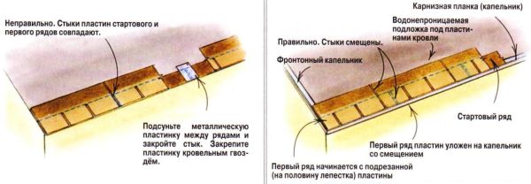
If the roofing plates are loose, the wind lifts the edges, allowing water to penetrate under the roofing. The number of cases of improper fastening should include a lack of fasteners, their location too high or low on the plate, and other shortcomings. Always follow the recommended plate fastening pattern and storm-fasten on all roofs in windy areas and on roofs with slopes greater than 10:12.
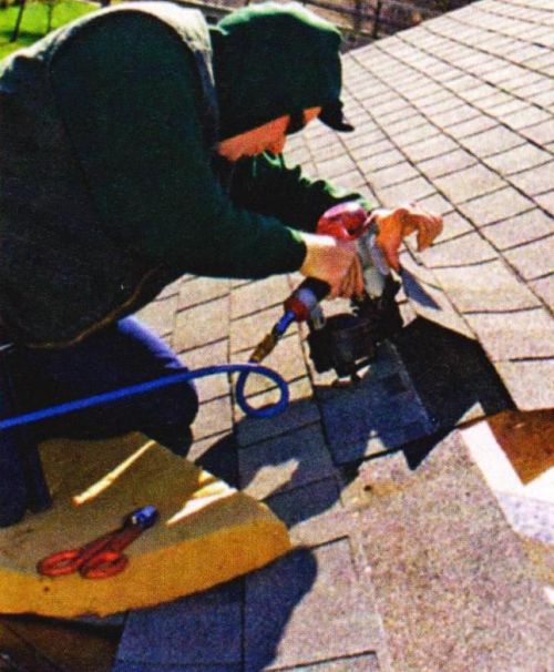
Position your nails correctly. They should pass through the fastening strip directly under the adhesive strip, where they will be covered by the petals of the plates of the next row. Open nails are the right way for water under the roof.
The causes of leaks are often flaws in the roof structure, which usually occur at the design stage. Design errors include improper placement of gutters or valleys that direct water to the walls, poor location of dormer windows, illiterate location for the chimney that prevents water from flowing, and overly intricate roof outlines.

It is almost impossible to correct such flaws in the project, since the house has already been built, but it is imperative to pay close attention to areas where leaks are likely due to this.
It may seem strange, but plates with a continuous adhesive strip can themselves cause leaks. Water, having fallen under a plate with a continuous adhesive strip on the side, will not be able to flow down and will move to the side until it finds an exit point, which is, as a rule, at the junction between the plates. This is where the leak starts. Valleys, chimneys, internal drains, vents are the most vulnerable places for water, allowing water to penetrate under the roof. Such leaks are very difficult to detect and eliminate their cause. Therefore, it is better not to risk it and use plates with an intermittent adhesive strip. If you must use sheets with a continuous adhesive strip, make sure that the aprons of the valleys and chimneys do not direct water into places where it can find its way under the coating.

Avoid using plates with a continuous adhesive strip. Water that has fallen under the plate on the side has no way out. Plates with intermittent adhesive strip allow water to drain through every interval.
"Fracture" of the package
Some roofers make the big mistake of loading a package of plates onto the roof, laying it down with the package folded over on the ridge. This can cause the plates to break and separate their layers, which will certainly affect the life of the new roof.
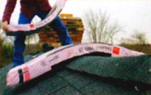
Always place packages on a flat roof surface. And further. Because cold sheets are more prone to cracking, try to avoid roofing in cold weather unless it's an emergency.
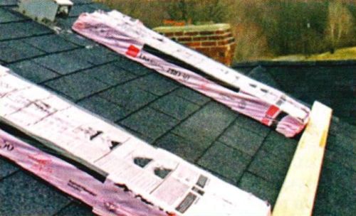
Do not bend the roofing plates over the ridge. This can lead to damage to the underlying material and reduce the life of the roof. Place the bags on a flat roof and use a stop to prevent them from slipping.
Connection errors
One of the causes of leaks may be incorrectly installed adjoining elements. For example, if the apron covers the adhesive strip of the roofing plate, then the plate of the next (upper, above the adjoining, row) will not be glued to the bottom.
|
The apron, when driving a nail into its upper edge, lifts the lower edge of the next row of roofing plates. An additional nail fixing the bottom edge of the apron is a potential leak site |
The apron should be flush with the top edge of the roofing plate and fixed with only one nail in the top corner. Between themselves, the adjoining elements should overlap by about 5 cm |

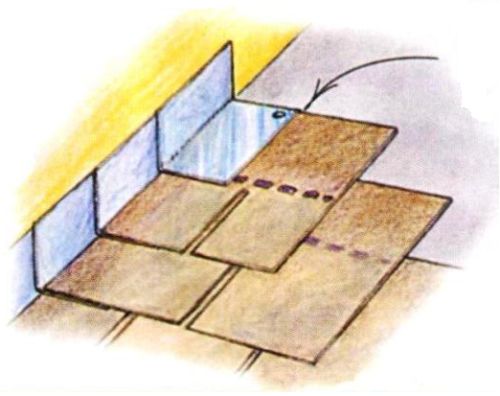
Sometimes they try to solve this problem by moving the apron slightly up so that its upper edge is higher than the edge of the roofing plate. When a nail is driven into the junction element, the upper edge of the roofing plate turns into a fulcrum. As a result, the flashing raises the bottom edge of the next row of roofing plate, creating a gap into which water can enter. The roofer attempts to remedy this by driving a nail into the bottom edge of the junction that will not be covered by the next row, which can also cause a leak.
The reason for many leaks is poor waterproofing of chimneys. However, before fixing this problem, check the condition of the masonry and make sure there are no loose bricks. The most common mistake when waterproofing chimneys is that roofers do not seal the apron flanges into the masonry.

The junction here should be made only from a sheet metal strip curved on the machine, strictly L-shaped in profile, carefully embedding the apron into the mortar between the rows of masonry. An abutment made without the use of a bending machine is a serious signal indicating the craftsman's inattention to detail. If you find a roof with a carelessly made chimney insulation, immediately look for other defects nearby.
Chimney waterproofing is a job for a professional. The places where chimneys and roofs meet are potential areas for leaks. If the masons did not put the aprons into the mortar between the rows of masonry, and the connection was made with nails and putty, this is very bad. The seams should be grooved with an angle grinder so that the apron can be securely patched between rows of masonry.
Leakage can easily occur due to operational damage to the roof. Television or satellite dishes, skylights and ventilation hatches should not be installed at random, but this happens quite often.

Overgrown tree branches can also destroy the integrity of the coating, and excessive shading of the roof contributes to the growth of moss on its surface, which also leads to damage to the roof.
Careless covering of valleys
One has only to be surprised that most of the valleys do not flow, given the widespread use of self-adhesive waterproof films in the practice of roofing as a coating in the valleys. Some inexpensive films have a warranty period of only 5 years. Roofing plates with a service life of 50 years over a film with a resource of 5 years are nonsense. The only reliable way to eliminate a leak in a valley is to completely block this problem area. When repairing valleys, always use not only a waterproof film, but also a metal apron.

Repairing a valley usually means covering it completely. Starting at the top, remove one entire roof plate from each side of the valley. Accuracy is extremely important here, since how well it can be reassembled depends on the thoroughness of disassembling the roof.

Roofing with undercut blades in valleys is often done incorrectly (left). Valleys with a metal apron are reliable (on the right).
Removing a damaged plate without harming its undamaged neighbors is not an easy task. This work is best done when the plates are cold enough that they won't buckle under your feet, but warm enough that they won't crack as you work. In summer, such repairs are best done in the early morning. In winter, such work should be avoided, except in urgent cases.
 |
Separate the glued plates in a row below and two rows above the plate to be removed. This may not be easy. Roofing plates, the service life of which is up to 50 years, are glued very firmly. In such cases, the adhesive strip will have to be cut. |
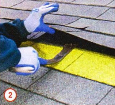 |
After the plates are separated from each other, you can remove the nails holding the damaged plate. |
 |
Before removing the plate, you need to pull out four more nails in a row |
 |
Now you can pull out the damaged plate, put a new one in its place and again fix the previously freed plates with nails. |
When fixing the repair plate, do not drive new nails into the holes from the previously pulled ones - they will most likely be squeezed out. Hammer nails next to the old holes, and put a little sealant into the last ones. Also glue all torn edges of the plates with sealant.