Strengthening the draft in the chimney with your own hands. How to make a do-it-yourself ventilation deflector - from a drawing to a finished device Do-it-yourself ventilation turbine drawings
A properly designed ventilation system provides clean and fresh indoor air. The main condition for its effective operation is the presence of traction. Unfortunately, debris and dust entering the channels can disrupt the normal operation of the equipment. To prevent this from happening, a deflector must be installed on the ventilation pipe.
If there is no deflector on the ventilation pipe, then its diameter will gradually decrease. To the greatest extent, this is facilitated by fat, which accumulates on the walls of the duct. It's where dust and debris sticks to.
The ventilation deflector is mounted on the pipe head. At first glance, this protects the channels from debris that may enter from the outside. But not everything is so simple. The device performs a number of functions, each of which is important.
Peculiarities
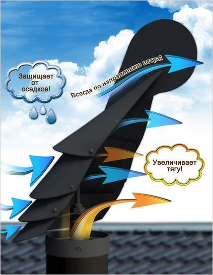
Installing a deflector on the ventilation pipe greatly increases the draft. The device deflects air currents. As a result, a zone of low pressure is formed at the outlet of the ventilation shaft. Due to this, the air inside the pipe rises. Thus, pressure compensation occurs.
There are many designs of deflectors, but they all work according to the principle described above. Interestingly, in most modern devices there is a narrowing of the channel. This allows you to achieve an increase in the speed with which the air flows over the pipe head. As a result, traction increases. This effect is called the airbrush principle.

If you use the deflector on the ventilation pipe correctly, you can achieve a significant increase in the efficiency of the entire system. With the right choice of device and its optimal installation, the increase in power can reach 20 percent.
Attention! The ventilation deflector shows the highest efficiency when installed on ventilation ducts with bends and large horizontal sections.
But the main purpose of the deflector is still to protect the duct from getting inside debris, insects, small birds and precipitation. Since the device is installed outside, the body material is stainless steel or ceramic. In some cases, you can also see ordinary plastic.
Advantages and disadvantages

Before you assemble the unit with your own hands, you need to find out not only its positive aspects, but also negative ones. First, let's focus on the positive. The umbrella structure effectively protects the pipe from precipitation and dirt, and an increase in traction can also be observed.
The main disadvantage of the deflector on the ventilation pipe is that when the wind blows from below, the flow hits the upper part of the structure and prevents the air from escaping normally. Therefore, sometimes there may be problems with the operation of the system. Fortunately, this happens quite rarely.
In addition, effective countermeasures were devised. Simply put, the structures began to be equipped with two cones, which are connected by bases. Therefore, if you want to get a truly reliable unit, this is best taken into account when creating a drawing.

Attention! The stronger the downward wind flow, the higher the pressure inside the ventilation deflector, which is installed on the pipe.
Kinds
There are many types of deflectors for ventilation pipes:
- The Tsagi deflector is very popular. The device has gained high popularity due to its simple design and high efficiency.
- The Grigorovich deflector is very popular.
- The H-shaped apparatus is most effective when installed on chimneys.
It is also quite common to find open structures. Since there are quite a lot of various designs on the market, they are classified according to the following parameters:
- pommel shape,
- rotary or turbine principle of operation,
- weathervane type.
A special role is played by the material from which the deflector is made. For example, plastic products have a relatively low price, but their service life is not very long. You can also note the sophisticated appearance.

It is because of the aesthetics that plastic deflectors can be seen on most pipes in private homes. Unfortunately, plastic does not tolerate high temperatures, so it cannot be installed on chimneys.
The rotating vent deflector enhances draft and effectively protects the channels from getting inside a variety of debris. The main feature of the device is a spherical shape.
A rotary vent deflector for a pipe can also be called a turbine. The device is capable of using wind energy to ensure the movement of the turbine. Inside, the air swirls like a tornado. This, in turn, increases the draft in the duct. As a result, good traction can be observed even in summer.
Grigorovich deflector

There are many varieties of ventilation deflectors for pipes. If we take into account the design, which combines simplicity and efficiency, then this is, of course, the Grigorovich unit.
This pipe vent deflector has a truncated cone. It is also called a diffuser. The ventilation pipe itself should go into it a little. A protective umbrella is mounted on top. Under it, a structure is installed that provides reduced pressure even with a side wind. It has the shape of a cone. Of course, such a design feature increases the traction force.
We make a deflector with our own hands
Preparatory work

To make a ventilation deflector with your own hands and install it on a pipe, you first need to perform certain preparatory work. The device consists of the following main elements:
- inlet pipe,
- diffuser,
- cap.
The best material to use is stainless steel. Its high anti-corrosion properties will ensure a long service life of the deflector on the ventilation pipe.

Before you start assembling with your own hands, you need to take care of the availability of the necessary tools, it includes:
- Bulgarian,
- drill,
- clamps,
- a hammer,
- roulette,
- metal scissors,
- bolts and nuts,
- rivets.
You also need to think about finding suitable sheets of metal for the unit. Particular attention should be paid to protective equipment. Do not start work without gloves and goggles.
The preparatory process also includes the creation of a drawing for a do-it-yourself ventilation deflector. It is worth recognizing that this is a rather difficult task. Of course, the design itself cannot be called super-complex, however, in order to get a unit suitable for long-term operation, everything must be carefully calculated.

It would be best to take a ready-made drawing, for example, one from this article. But you must take into account that your pipe sizes may be completely different. Therefore, during the implementation of the project, additional adjustments may need to be made. The best option would be to contact the design bureau, where they will make you a finished project that you can bring to life with your own hands.
Assembly

After you prepare all the necessary tools and take care of personal protection, you can begin the process itself. First you need to transfer the contours from the drawing to the metal. In doing so, special attention is paid to the following elements:
- cap,
- diffuser
- outer cylinder,
- racks.
The final result in the form of a ready-to-work unit depends on how carefully you draw everything. Once the marks are made, you can start cutting out the desired shapes, of course, for this you will need metal scissors.

To connect the cut elements together, use a rivet gun. At the same time, racks will act as peculiar bridges between the two parts of the main structure.
Attention! The posts must be cut from the same metal as the two main parts of the unit.
After the unit is assembled, it can be installed on the head of the pipe. In this case, the structure itself is fastened with clamps. On this, the manufacturing and installation process can be considered completed.
Results
The ventilation deflector is an important element in the ventilation system. It allows you to increase system performance by 20 percent and at the same time protects internal channels from debris, dust and precipitation. Most often, units of this class are made of stainless steel sheets, but other options are possible.
The inflow of clean air into the room is provided by the ventilation system. Its effectiveness depends on internal traction. If dust and debris enter the air ducts, the normal operation of the devices is disrupted. To eliminate such a possibility, a ventilation deflector is installed at the outlet of the pipe - a device that forms draft in the ventilation ducts . What is such a unit for? – This device is able to protect the air duct shafts from moisture, snow and rain.
note! The absence of this solution leads to a gradual decrease in the diameter of the pipe due to the fact that small particles of debris, dust and grease accumulate on the walls of the pipes..
A wide range of models is on sale. Their device and principle of operation are discussed below. The simplest models can be made by hand.
- metal glasses (there are 2 in the standard version);
- fixing brackets for secure fastening;
- supply and discharge pipe, which is put on the pipe and fastened with a clamp.
- directed wind currents hit the metal hulls;
- due to diffusers, the air branches, as a result of which the pressure level decreases;
- in the pipe of the system, the thrust increases.
- the design and shape of the hull;
- unit size;
- installation height.
- TsAGI - thrust is enhanced due to air and thermal pressure, high-altitude pressure drop. It is mounted directly in the ventilation duct, which makes routine inspections and cleaning difficult;
- spherical or round (such as "Volper");
- Khanzhenkov's solutions in the form of an open plate - the main structural difference lies in the additional wall located around the air duct. The exhaust hood has the shape of a plate;
- rotary products (hood, net) - a wind chute that rotates on a special rod. Due to turbulence, the thrust in the channel increases;
- units operating according to the principle described by Grigorovich;
- in the form of a star.
- ASTATO;
- TsAGI plate type.
- stainless steel sheet type, can be replaced with galvanized;
- electric drill;
- fixing clamps, bolts, rivets and nuts;
- drawing tool for metal surfaces;
- compass;
- sheet cardboard;
- ruler;
- scissors for metal and paper.
- the height of the deflector is equal to 1.6 of the diameter of the chimney.
- the width of the diffuser is 1.2 times greater than the diameter of the chimney.
- the width of the cover is equal to two diameters of the chimney.
Show all
Ventilation deflector device
Each turbo deflector for ventilation consists of several functional elements:
The shape of the outer glass differs in shape, expanding at the bottom. As for the bottom, it is absolutely flat. The cylinders are put on one on top of the other, and a cover is fixed on the racks at the top.
Attention! The diameter of the lid must be larger than the outlet opening to avoid rain falling into the system.
The figure below shows the components of different types of structures.
note! The installation of the rebounds is carried out in such a way that the street air creates an additional suction through the recesses between adjacent rings. Thanks to this, it is possible to speed up the removal of "heavy oxygen" from the ventilation system..
The deflector devices in the ventilation system of the house are implemented in such a way that when air flows from the bottom to the top, the device does not work well: it is reflected from the roof surface, after which oxygen rushes to the gases exiting at the top of the hole. This disadvantage is typical for all units. To eliminate it, 2-cone solutions are required, interconnected by a "bridge".
If the wind has a lateral direction, then the output of air masses is carried out both from below and from above. The vertical orientation of oxygen promotes outflow from below.
What is a turbo deflector? Ventilation without electricity. Replacement of conventional ventilation system


The principle of operation of the ventilation deflector
The ventilation deflector works according to a simple principle, regardless of the design and model of the device:
The principle of operation of the device
The greater the resistance created by the base of the case, the more efficient the outflow of air in the channels of the systems. It is generally accepted that the device installed on the roof at a slight inclination to the horizontal plane works better. Experts state that the effectiveness of these devices is determined by 3 factors:
No matter how reliable and high-quality ventilation deflectors are, they have both advantages and disadvantages, which I would like to dwell on in more detail.
About the "pros" and cons of deflectors
As mentioned above, umbrella solutions can effectively prevent dirt and precipitation from entering the air ducts. With proper selection and professional installation of the deflector, ventilation improves. The efficiency of the system as a whole is increased by 20%.
The ventilation device helps to create or increase air draft in the exhaust ventilation ducts
Advice! For regions with weak winds, it is recommended to equip the system with a device to increase the air supply and exhaust. It will eliminate the effect of "overturning" thrust.
The devices are not without drawbacks: with a vertical wind direction, the flow comes into contact with the upper section of the structure, while the air cannot be fully discharged into the street. To eliminate such an effect, designs with 2 cones were invented. In winter, frost appears on the base of the pipes, so it is necessary to regularly carry out preventive examinations.


Types of deflectors
After analyzing or taking a quick look at the types of deflectors on the market, one can come to a state of slight confusion at the number of solutions available.
From the point of view of the design of the device, it is customary to divide into several types:
From the point of view of simplicity of design and the possibility of implementation, Grigorovich's ventilation device holds unconditional leadership. It consists of several pairs of umbrellas arranged in one "plate", which is mounted above the channel wall.
Grigorovich's device
In the last 2-3 years, a variety of products have been on sale that do not have a clear belonging to any type: a rotating deflector with spiral blades, an umbrella, units on bearings.
When choosing a particular model, paramount attention is paid to its design. This is one of the key parameters of the product. Having decided on the constructive type of the device, the optimal size of the unit is selected for a particular case. It is easier to choose the right apparatus if you answer a simple question - why the structure is installed and for what object.
Top Models:
When choosing, take into account the coefficient of losses and rarefaction of air. It follows that these values depend on the specific model. If we are talking about solutions of the DS type, the corresponding coefficient will be 1.4. Obviously, the degree of air rarefaction depends on the wind speed, see Table. below:
Device selection table
Do-it-yourself ventilation deflector
Knowing about the device and the principle of operation of the device, many owners decide to make a ventilation deflector with their own hands. From the point of view of his own implementation, the version of Grigorovich's product is unrivaled, so we will consider the implementation of this particular version. The main advantage is that such ventilation works without electricity, all year round.
You must first prepare:
Calculation of device parameters (Grigorovich)
We give you the simplest calculation option, without any formulas:
Based on the available dimensions and drawings, individual elements of the deflector are cut out of cardboard. To create a rotating device, certain skills are required, so it is better to practice on mock-ups and only then proceed to a metal counterpart.
Construction manufacturing
Patterns must be attached to metal sheets, and then circled with a scriber. Further, the algorithm is simple - with metal scissors we cut out the elements and details of the future design. Separate parts are interconnected with rivets and bolts. If the mechanism is active, then it is better to fix the parts by welding.
Mockups deflectors for ventilation systems made of cardboard
To securely fasten the rotational hood, several curved metal strips should be prepared, which will take on the role of brackets.
We fix the brackets with rivets or bolts
As for the reverse cone, it makes sense to fix it at the umbrella.
Deflector
Installation work
The lower of the 2 glasses is installed on the outlet chimney. The top glass is attached to it. For a greater stability design, 2 parts are clamped with a clamp, the same is done with exhaust holes. The cap is pressed with prepared brackets. If we are talking about a region where the direction of the wind often changes, it makes sense to equip the unit with a reverse cone, which will allow the unit to fully operate in any wind direction.
So, in this article we examined what a deflector is in ventilation. Summing up, we can say that this is a simple and effective device that improves the ventilation of objects of any complexity, be it public buildings or residential buildings. A small element increases the performance of the ventilation system by 15-20%, reliably protecting the interior from precipitation, small particles, debris and dust.
To drive the wind generator, a rotary-type turbine with a vertical axis of rotation was made. This type of rotor is very strong and durable, has a relatively low rotational speed and can be easily made at home, without the aerodynamic wing profile and other problems associated with the manufacture of a propeller for a horizontal axis of rotation wind turbine. Moreover, such a turbine operates almost silently and regardless of where the wind blows. The work is practically independent of turbulence and frequent changes in the strength and direction of the wind. The turbine is characterized by high starting torques, operation at relatively low speeds. The efficiency of this turbine is small, but this is enough to power devices of low power, everything pays off with the simplicity and reliability of the design.
Electric generator
A modified compact car starter with permanent magnets is used as a generator. Generator output: alternating current with a power of 1.0 ... 6.5 W (depending on wind speed).
The option of converting a starter into a generator is described in the article:

Wind turbine manufacturing
This wind turbine costs next to nothing and is easy to manufacture.
The design of the turbine consists of two or more semi-cylinders mounted on a vertical shaft. The rotor rotates due to the different resistance to the wind of each of the blades turned to the wind with different curvature. The efficiency of the rotor is somewhat improved by the central gap between the blades, since some air additionally acts on the second blade as it exits the first.
The generator is fixed on the stand behind the output shaft, through which the wire with the received current exits. This design eliminates the sliding contact for current pickup. The turbine rotor is mounted on the generator housing and fixed to the free ends of the mounting studs.
A disk with a diameter of 280 ... 330 mm or a square plate inscribed in this diameter is cut out of an aluminum sheet 1.5 mm thick.
Five holes are marked and drilled relative to the center of the disk (one in the center and 4 at the corners of the plate) for installing the blades and two holes (symmetrical to the central one) for fixing the turbine to the generator.
In the holes located at the corners of the plate, small corners made of aluminum, 1.0 ... 1.5 mm thick, are installed to secure the blades.


The turbine blades will be made from a can with a diameter of 160 mm and a height of 160 mm. The can is cut in half along the axis, resulting in two identical blades. The edges of the can after the cut, at a width of 3 ... 5 mm, are bent 180 degrees and crimped to strengthen the edge and eliminate sharp cutting edges.


Both blades of the turbine, from the side of the open part of the can, are interconnected by a U-shaped jumper with a hole in the middle. The jumper forms a gap 32 mm wide between the central part of the blades to improve the efficiency of the rotor.

On the opposite side of the can (near the bottom), the blades are interconnected by a bridge of minimum length. In this case, a gap of 32 mm wide is maintained along the entire length of the blade.

The assembled block of blades is installed and attached to the disk at three points - behind the central opening of the jumper and the previously installed aluminum corners. The turbine blades are fixed on the plate strictly one against the other.
To connect all the parts, you can use rivets, self-tapping screws, an M3 or M4 screw connection, corners, or use other methods.

A generator is installed in the holes on the other side of the disk and fixed with nuts on the free ends of the mounting studs.

For reliable self-starting of the wind generator, it is necessary to add a second similar tier of blades to the turbine. In this case, the blades of the second tier are displaced along the axis relative to the blades of the first tier by an angle of 90 degrees. The result is a four-blade rotor. This ensures that there is always at least one blade that is able to catch the wind and give the turbine a boost to spin.
To reduce the size of the wind generator, a second layer of turbine blades can be made and fixed around the generator. We will make two blades 100 mm wide (generator height), 240 mm long (similar to the length of the blade of the first tier) from an aluminum sheet 1.0 mm thick. We bend the blades along a radius of 80 mm, similarly to the blades of the first tier.

Each blade of the second (lower) tier is fixed with two corners.
One is installed in a free hole on the periphery of the disk, similar to the fastening of the blades of the upper tier, but with a shift at an angle of 90 degrees. The second corner is fixed to the stud of the installed generator. In the photo, for clarity of fastening the blades of the lower tier, the generator is removed.
in channels and ducts. But over time, debris can get into the shaft, the channels can simply become clogged with dust, which adheres firmly to their walls, especially if they have a greasy coating. All this reduces the diameter of the air ducts, which negatively affects the operation of the entire ventilation system.
That is why many homeowners install special devices called deflectors on the heads of the ventilation pipes.
Features of the device
installed to increase draft in air ducts, mines and channels. This device, deflecting the air currents created by the wind, creates a zone of low pressure at the outlet of the ventilation system. The air masses in the pipe, trying to compensate for the rarefaction, rise to the head of the pipe, thereby increasing the draft.This is a description of the principle of operation of all deflectors, of which there are a huge number of designs. Many devices not only deflect air flows, but also increase the speed of their passage over the head of the ventilation pipe, due to the narrowing of the channel, thereby significantly increasing the draft (airbrush principle).
Proper use of the deflector helps to increase the performance of the entire ventilation system by up to 20%, it is especially useful on ventilation ducts with large horizontal sections and bends.
In addition, the deflector on the ventilation pipe perfectly protects against the ingress of various debris, small birds, insects, and most importantly, atmospheric precipitation. Basically, the material from which these devices are made is resistant to corrosion. It is galvanized or stainless steel, ceramic or plastic.
Existing types of deflectors
To date, there are a huge number of different designs of such devices. Among them, the most popular models are:
- - an effective and simple structural device for redirecting the wind.
- - also a very popular deflector design.
- H-shaped device for effective increase of draft in ventilation and chimneys.
In addition, various designs of open deflectors are often used both on the heads of ventilation and chimneys.
All varieties of models can be classified according to some distinctive qualities:
- According to the shape of the top of the device.
- Rotating (rotary or turbine).
- Deflectors-weathervanes.
In addition to such a common material as metal, these devices are made of plastic. The plastic ventilation deflector is less durable than its steel counterpart, but has a lower cost and a more sophisticated appearance.
That is why plastic fixtures adorn the ventilation shafts of most private houses. But he, besides the service life, has another serious drawback. Plastic does not tolerate high temperatures, so it is not recommended to use it on chimneys.
 Weathercocks - deflectors are usually installed on chimneys, but they are quite suitable for ventilation systems. The air flow, passing through the system of peaks and slots in the body of the product, is redirected due to which a zone of low pressure is created above the pipe. It should be recalled that the weather vane has a design that allows you to constantly turn this device, the working side to the wind.
Rotating due to its design not only enhances the draft in the ventilation shaft, but also effectively protects it from various debris and insects. This device, as a rule, has a spherical shape, therefore it stands out among all with its original design.
There is another original type of ventilation deflector - rotational, or as it is also called turbine. This device converts the energy of air flows into the rotational movement of the turbine, which spins the air, according to the principle of a tornado, thereby creating an increase in traction in the duct. This device shows excellent results even in the warm season, creating traction in the ventilation system.
Making the simplest do-it-yourself device
 Despite the complexity of the design, every home master can make a deflector with his own hands. It is enough just to have the necessary tools and materials. To make this device yourself, you will need:
- A sheet of thick paper or cardboard.
- Sheet of galvanized metal.
- Drawing of the deflector with calculations regarding the diameter of the pipe.
- Rivet gun.
- Metal scissors.
- Drill with a set of drills.
- Marker or scriber.
After preparing the tool, material and personal protective equipment (glasses, gloves), you can start making a ventilation deflector with your own hands.
- First of all, you should transfer the contours of the product from the drawing to the metal. There should be a sweep of all the main parts of the device: a cap, a diffuser, an external cylinder, racks.
- After that, you need to cut out all parts of the device, according to the resulting pattern.
- Connect all parts of the device, according to the drawing or sketch, using a rivet gun.
- Connect the two parts of the deflector using racks cut from the same metal.
After manufacturing, you can install the deflector on the pipe head, carefully securing it with clamps.
Advice:
The deflector will create additional traction in the channels only if all its parts are made to a certain size. It should be remembered that the installation should be carried out while working at height, so it is better to do this with two people and with insurance. If you are not confident in your abilities, contact professionals who have experience in the manufacture and installation of these necessary devices.
The activity of both individuals and all of today's humanity is practically impossible without electricity. Unfortunately, the rapidly increasing consumption of oil and gas, coal and peat leads to a decrease in the reserves of these resources on the planet. What can be done while earthlings still have all this? According to the conclusions of experts, it is the development of energy complexes that can solve the problems of world economic and financial crises. Therefore, the most relevant are the search and use of fuel-free energy sources.
Renewable, ecological, green
Perhaps it is not worth reminding that everything new is a well-forgotten old. People have learned to use the strength of the river flow and the speed of the wind to obtain mechanical energy for a very long time. The sun heats water for us and moves cars, feeds spaceships. Wheels, installed in the beds of streams and small rivers, supplied water to the fields as early as the Middle Ages. One could provide flour to several surrounding villages.
At the moment, we are interested in a simple question: how to provide your home with cheap light and heat, how to make a windmill with your own hands? 5 kW power or a little less, the main thing is that you can supply your home with current for the operation of electrical appliances.
It is interesting that in the world there is a classification of buildings according to the level of resource efficiency:
- conventional, built before 1980-1995;
- with low and ultra-low energy consumption - up to 45-90 kWh per 1 kV/m;
- passive and non-volatile, receiving current from renewable sources (for example, by installing a rotary wind generator (5 kW) with your own hands or a system of solar panels, you can solve this problem);
- energy-active buildings that generate more electricity than they need, receive money by giving it through the network to other consumers.
It turns out that our own, home mini-stations installed on rooftops and in yards can eventually compete with large electricity suppliers. And the governments of different countries in every possible way encourage the creation and active use

How to determine the profitability of your own power plant
Researchers have proven that the reserve capacity of the winds is much greater than all the accumulated centuries-old fuel reserves. Among the methods of obtaining energy from renewable sources, windmills have a special place, since their manufacture is simpler than the creation of solar panels. In fact, a 5 kW wind generator can be assembled with your own hands, having the necessary components, including magnets, copper wire, plywood and metal for the blades.
Connoisseurs argue that not only a structure of the correct shape, but also built in the right place can become productive and, accordingly, profitable. This means that it is necessary to take into account the presence, constancy and even speed of air flows in each individual case and even in a particular region. If calm, calm and calm days periodically come in the area, the installation of a mast with a generator will not bring any benefit.
Before you start making a windmill with your own hands (5 kW), you need to consider its model and appearance. Do not expect a large energy output from a weak design. Conversely, when you only need to power a couple of light bulbs in the country, it makes no sense to build a huge windmill with your own hands. 5 kW is enough power to provide electricity to almost the entire lighting system and home appliances. There will be constant wind - there will be light.

How to make a wind generator with your own hands: a sequence of actions
At the place chosen for the high mast, the windmill itself is strengthened with a generator attached to it. The generated energy goes through the wires to the desired room. It is believed that the higher the mast design, the larger the diameter of the wind wheel and the stronger the air flow, the higher the efficiency of the entire device. In fact, everything is not quite like this:
- for example, a strong hurricane can easily break the blades;
- some models can be installed on the roof of an ordinary house;
- A properly selected turbine starts easily and performs well even in very low wind speeds.

The main types of windmills
Designs with a horizontal axis of rotation of the rotor are considered classic. Usually they have 2-3 blades and are installed at a great height from the ground. The greatest efficiency of such an installation is manifested at a constant direction and its speed of 10 m/s. A significant disadvantage of this bladed design is the failure of the rotation of the blades with frequently changing, impetuous. This leads either to unproductive work or to the destruction of the entire installation. To start such a generator after stopping, a forced initial spin-up of the blades is necessary. In addition, with active rotation, the blades emit specific sounds that are unpleasant to the human ear.
The vertical wind generator ("Volchok" 5 kW or other) has a different placement of the rotor. H-shaped or barrel-shaped turbines capture wind from any direction. These designs are smaller, run even at the weakest air flows (at 1.5-3 m/s), do not require high masts, they can be used even in urban environments. In addition, do-it-yourself (5 kW - this is real) assembled windmills reach their rated power with a wind of 3-4 m / s.

Sails are not on ships, but on land
One of the most popular trends in wind energy today is the creation of a horizontal generator with soft blades. The main difference is both the material of manufacture and the shape itself: do-it-yourself windmills (5 kW, sail type) have 4-6 triangular fabric blades. Moreover, unlike traditional structures, their cross section increases in the direction from the center to the periphery. This feature allows not only to "catch" a weak wind, but also to avoid losses during a hurricane air flow.
The advantages of sailboats include the following indicators:
- high power at slow rotation;
- self-orientation and adjustment to any wind;
- high vane and low inertia;
- no need for forced spinning of the wheel;
- completely silent rotation even at high speeds;
- absence of vibrations and sound disturbances;
- relative cheapness of construction.

DIY windmills
5 kW of required electricity can be obtained in several ways:
- build a simple rotary structure;
- to assemble a complex of several successively located on the same axis of the sailing wheels;
- use an axial construction with neodymium magnets.
It is important to remember that the power of the wind wheel is proportional to the product of the cubic value of the wind speed and the swept area of the turbine. So, how to make a 5 kW wind generator? Instructions below.
As a basis, you can take a car hub and brake discs. 32 magnets (25 by 8 mm) are placed in parallel in a circle on the future disks of the rotor (moving part of the generator) for each disk, 16 pieces, moreover, the pluses necessarily alternate with the minuses. Opposite magnets must have different pole values. After marking and placement, everything on the circle is poured with epoxy.
Coils of copper wire are placed on the stator. Their number should be less than the number of magnets, that is, 12. First, all the wires are brought out and connected to each other with a star or triangle, then they are also filled with epoxy glue. It is recommended to insert pieces of plasticine into the coils before pouring. After the resin has hardened and removed, holes will remain that are needed for ventilation and cooling of the stator.

How it all works
The rotor disks, rotating relative to the stator, form a magnetic field, and an electric current appears in the coils. And the windmill, connected by means of a system of pulleys, is needed in order to move these parts of the working structure. How to make a wind generator with your own hands? Some start building their own power plant by assembling a generator. Others - from the creation of a bladed rotating part.
The shaft from the windmill is coupled with a sliding joint to one of the rotor discs. A lower, second disk with magnets is placed on a strong bearing. The stator is located in the middle. All parts are attached to the plywood circle with long bolts and fixed with nuts. Between all the "pancakes" be sure to leave minimal gaps for free rotation of the rotor discs. The result is a 3-phase generator.
"Barrel"
It remains to make windmills. With your own hands, a 5 kW rotating structure can be made from 3 circles of plywood and a sheet of the thinnest and lightest duralumin. Metal rectangular wings are attached to plywood with bolts and corners. Preliminarily, wave-shaped guide grooves are hollowed out in each plane of the circle, into which the sheets are inserted. The resulting two-story rotor has 4 wavy blades attached to each other at right angles. That is, between each two hubs fastened with plywood pancakes, there are 2 duralumin blades curved in the shape of a wave.
This design is mounted in the center on a steel stud, which will transmit torque to the generator. Do-it-yourself (5 kW) windmills of this design weigh approximately 16-18 kg with a height of 160-170 cm and a base diameter of 80-90 cm.
What to Consider
A windmill-“barrel” can be installed even on the roof of a building, although a tower 3-4 meters high is quite enough. However, it is imperative to protect the generator housing from natural precipitation. It is also recommended to install an energy storage battery.
To obtain an alternating current from a direct 3-phase current, a converter must also be included in the circuit.
With a sufficient number of windy days in the region, a self-assembled windmill (5 kW) can provide current not only to a TV and light bulbs, but also to a video surveillance system, air conditioning, refrigerator and other electrical equipment.