Twisted pair coil for metal detector. Need help from a metal detector, in search of a cable! Ears for bar
Making a Good Coil
Usually, metal detector coils are wound in bulk on some kind of mandrel - a saucepan, a can, etc. suitable diameter. Then wrap with electrical tape, shielding foil and again with electrical tape. Such coils do not have the necessary structural rigidity and stability, are very sensitive to the slightest deformation and change the frequency greatly even with simple finger pressure! A metal detector with such a coil will have to be adjusted every now and then, and from the knob-regulator your fingers will constantly be in big sore corns :). It is often recommended to “fill in epoxy” with such a coil, but where should you fill it, epoxy, if the coil is frameless? the same, providing simple fastening to a stick-rod without any brackets.
For the coil frame, you can make it using a plastic box (cable channel) of a suitable section. For example, for 80 - 100 turns of wire with a cross section of 0.3 ... 0.5 mm, a box with a cross section of 15 X 10 or less is quite suitable, depending on the cross section of your particular wire for winding. A single-core copper wire for low-current electrical circuits is suitable as a winding wire; it is sold in coils, such as CQR, KSPV, etc. This is a bare copper wire in PVC insulation. The cable can contain from 2 or more single-core wires with a cross section of 0.3 ... 0.5 mm in insulation of different colors. We remove the outer sheath of the cable and get a few necessary wires. Such a wire is convenient in that it excludes the possibility of a short circuit of the turns in case of poor-quality insulation (as in the case of a wire with varnish insulation of PEL or PEV grades, where minor damage to it is not visible to the eye). To determine how long the wire should be to wind the coil, you need to multiply the circumference of the coil by the number of its turns and leave a small margin for the conclusions. If there is no piece of wire of the required length, you can make a winding of several pieces of wire, the ends of which are well soldered to each other and carefully insulated with tape or heat shrink tubing.
We remove the cover from the cable channel and cut the side walls with a sharp knife after 1 ... 2 cm:

After that, the cable channel can easily go around the cylindrical surface of the required diameter (jar, pan, etc.), corresponding to the diameter of the metal detector coil. The ends of the cable channel are glued together and a cylindrical frame with sides is obtained. It is easy to wind the required number of turns of wire on such a frame and coat them, for example, with varnish, epoxy, or fill everything with sealant.

From above, the frame with the wire is closed with a cable channel cover. If the sides of this cover are low (this depends on the size and type of the box), then side cuts on it can be omitted, because it already bends quite well. The output ends of the coil are brought out next to each other.

This results in a sealed coil with good structural rigidity. All sharp edges, protrusions and irregularities in the cable channel should be smoothed out with sandpaper or wrapped with a layer of electrical tape.

After checking the coil for operability (this can be done by connecting the coil even without a screen to your metal detector by the presence of generation), filling it with glue or sealant and machining the irregularities, you should make a screen. To do this, take foil from electrolytic capacitors or food foil from the store, which is cut into strips 1.5 ... 2 cm wide. The foil is wound around the coil tightly, without gaps, overlapping. Between the ends of the foil in the place of the coil leads must be left gap 1 ... 1.5 cm , otherwise a short-circuited coil is formed and the coil will not work. The ends of the foil should be secured with glue. Then, from above, the foil is wrapped along the entire length with any tinned wire (without insulation) in a spiral, in increments of about 1 cm. The wire must be tinned, otherwise incompatible metal contact (aluminum-copper) may occur. One of the ends of this wire will be the common wire of the coil (GND).

Then the whole coil is wrapped with two or three layers of electrical tape to protect the foil-screen from mechanical damage.
Tuning the coil to the desired frequency consists in the selection of capacitors, which, together with the coil, form an oscillatory circuit:

The actual inductance of the coil, as a rule, does not correspond to its calculated value, so the desired circuit frequency can be achieved by selecting the appropriate capacitors. To facilitate the selection of these capacitors, it is convenient to make the so-called "capacity store". To do this, you can take a suitable switch, for example, type P2K for 5 ... 10 buttons (or several such switches with fewer buttons), with dependent or independent fixation (anyway, the main thing is to be able to turn on several buttons at the same time). The more buttons on your switch, the correspondingly more containers can be included in the "shop". The scheme is simple and is shown below. The entire installation is hinged, the capacitors are soldered directly to the button terminals.


Here is an example for selecting capacitors series resonant circuit
(two capacitors + coil) with capacitances of about 5600 pF. By switching the buttons, you can use different capacities indicated on the corresponding button. In addition, by turning on several buttons at the same time, you can get the total capacity. For example, if you simultaneously press buttons 3 and 4, we get total capacitances of 5610 pF (5100 + 510), and when you press 3 and 5 - 5950 pF (5100 + 850). Thus, it is possible to create the necessary set of capacitances for the exact selection of the desired loop tuning frequency. You need to choose the capacitor capacities in the "capacitance store" based on the values \u200b\u200bthat are given in your metal detector circuit. In the example given here, the capacitances of the capacitors according to the circuit are 5600pF. Therefore, the first thing included in the "shop" is, of course, these containers. Well, then take containers with lower ratings (4700, 4300, 3900 pF for example), and very small ones (100, 300, 470, 1000 pF) for a more accurate selection. Thus, by simply switching the buttons and their combination, you can get a very wide range of capacitances and tune the coil to the required frequency. Well, then it remains only to pick up capacitors with a capacity equal to the one you got as a result on the “capacity store”. Capacitors with such a capacity should be placed in the working circuit. It should be borne in mind that when selecting containers, the “store” itself must be connected to a metal detector exactly with the wire / cable that will be used in the future, and the wires connecting the “store” to the coil must be made as short as possible! Because all wires also have their own capacitance.

Discuss the article METAL DETECTORS: ABOUT COILS
Alternative sensors for a metal detector
Koschei-18M (VM8043)
Part 6. New Concentric Sensor
Despite the fact that we have already developed and published several alternative sensor designs for this metal detector, concentric “ring” type sensors are still in the greatest demand. They are ergonomic, versatile, produced by many manufacturers. However, plastic cases, which are described and which were previously completed with our kits, unfortunately, are discontinued due to reasons beyond our control. And the developed ones turned out to be “too tough” for not all do-it-yourselfers because of the troublesome “ fiberglass-foam" technology. However, available for sale new plastic cases with a diameter of 200mm. They are quite suitable for sensors of induction metal detectors. True, pouring a precision system of coils of such sensors directly into this housing is somewhat problematic. Therefore, we have developed a special casting mold, manufactured using blister technology. Serial production of such forms has now been mastered.
It is worth noting that the winding wires must be new with perfect insulation. Only copper winding wires can be used. It is unacceptable to use used wire, extracted from the windings of electrical devices - as a rule, it has microcracks that can lead to interturn short circuits, which will spoil the result of all painstaking work.
First, we take a casting mold and put strips of fiberglass or ordinary fabric (for reinforcement) into the radial “knitting needles” of the recesses. We lay our coils on top. Before laying the knots of the tightening threads, we unfold so that they are at the bottom. This will lift the coils and allow the resin to flow easily under them.
Next, we connect the coils to the cable according to the diagram. Particular attention should be paid to the phasing of the coils when soldering the cable. The transmitting and compensating coils must be turned on in opposite directions. For ease of perception, the diagram conventionally shows the beginnings and ends of all coils in the form of leads coming out of the coils in a certain direction. This is exactly how you need to orient and solder the ends of "real coils". The figure below shows how to connect the sensor using a “thick” S - VHS cable Belsis BW 7809 PL . Such a cable gives a slightly higher consumption of the device than when using AWM 2919 (thick VGA - double-shielded cable used in computer monitors and plasma displays) or LIYCY-CY (installation low-current cable with double shielding). but BW 7809PL much easier to desolder.

We fix the conclusions of the coils with the help of a small cylinder of plasticine. In addition to fixing the leads, it plays another important technological role - in the future, it forms the places where the wires exit from the casting mass. To do this, in the blister form there is a small cylindrical recess, which should tightly fill the lower end of the plasticine cylinder. The inputs of the winding wires into the cylinder must be located at the level of the horizontal surface of the blister-shaped plastic, and the outputs in the direction of the cable soldering should be above the level of the epoxy resin.

Now we proceed to the preliminary balancing of the sensor. To do this, place the sensor away from metal objects and turn on the “Path Calibration” service mode. Details of entering this mode are described. First, we need to turn on the operating frequency of 7 kHz, Set Gain 1 and a phase shift in the region of 150-160 degrees. The winding data of the coils is chosen in such a way that at first the compensating coil creates a slight overcompensation. In this case, the scale X and Y deviate to the right. And when you try to slightly raise the small coil above the form, this picture only gets worse. Those. the scales should not go to the left through zero. If, when you lift, the scale readings still go through zero, it means that due to errors in the diameters of the wire or mandrels, it turned out to be small undercompensation. However, in this case, the sensor can also be balanced, which will be discussed below.
Consider a way to eliminate a small overcompensation. To do this, we need to slightly remove the compensating coil from the receiver. We do this with a wooden toothpick - we introduce it under the turns of the compensating coil and bend them slightly towards the center. At the same time, we monitor the readings, trying to get a zero balance on both scales. X and Y .

Because the wire of the compensating coil is quite rigid, the bent turns do not need additional fixation. Following the readings of the scales, we bend the required number of turns. If for the balance there are not enough turns of one sector between the thread ties, we move on to another sector. Having achieved readings close to zero at amplification 1, install Gain 8 and correct the position of the turns. Having achieved an unbalance of no worse than ±20%, preliminary balancing can be considered completed. We unsolder the cable and proceed to pouring the coils with epoxy resin. For these purposes, we need about 100-110 grams of resin. At the end of the filling, we bend the “tails” of the reinforcing tapes inside the “knitting needles” and leave the mold on a flat surface for 24 hours to solidify the resin.

After the resin hardens, remove the casting from the mold. At the same time, you can not spare the form - in the right places we chop it with scissors. We remove the plasticine, and through the resulting hole we stretch the ends of the wires to the other side of the casting. As a result, we get such an elegant and durable design:

Now the sensor needs to be shielded. For these purposes, we use the same conductive varnish based on nitro-lacquer and crushed graphite. Preparation details are described. In this design, it is not the housing that is shielded, but the directly filled coils. Using a brush, varnish the “small ring”. Do not forget to install a ground terminal - a small piece of stranded insulated wire, one end of which must be stripped and “fluffed”, and then lubricated with conductive varnish. For convenience, this conductor can be pre-fixed with a drop of hot melt adhesive.

Attention: The transmitting coil does not need to be shielded! In this design, it is not only redundant, but also harmful. It is redundant because the Koshchei-18M output stage has a very low impedance, so the transmitting coil is practically not subject to the capacitive effect. And it is harmful, because when the screen is close to the transmitting coil, tangible induction currents begin to flow in it, which lead to screen degradation and, as a result, to false responses.
Next, proceed to the placement of the sensor inside the case. We fasten the pressure seal to the bracket. It is advisable to fix the gland nut with some kind of glue or compound. Then we pass the end of the cable through the cable gland.

Now we bend this end of the cable and tightly lay it inside the bracket, then securely fix it with hot glue.

Next, we proceed to the preparation of the housing covers. On the top cover, using side cutters or a scalpel, you need to remove four bosses (blue arrows). Then we drill six holes with a diameter of 3mm and countersink them with a 6-7mm drill under the head of the self-tapping screw (green arrows). Then we drill a hole with a diameter of 7-8mm for the cable (red arrow). On the bottom cover, only remove the bosses. We do not throw away the bosses, they will be useful to us later.

Next, we thread the end of the cable into the hole on the cover and fasten the bracket using stainless steel screws 3x16mm. In the area of \u200b\u200bthe “ears” of the bracket, to increase the strength of the connection, self-tapping screws 3x20mm or 3x25mm can be used. Attention: self-tapping screws must be stainless steel. They, unlike conventional steel ones, do not lead to unbalance of the sensor.

Now we need to fix the sensor inside the top case cover. To do this, lift the sensor and apply hot glue inside the case in the places shown by the arrows. The hot melt must be well heated. Then firmly press the sensor to the cover. At the cable exit point (blue arrow), the adhesive should protrude inward and seal hole around the cable. We orient the ends of the cable along the bottom of the formed “bath”, into which the final filling will be made, fixing the winding leads. Regarding hot glue, we want to note that “not all washing powders are equally good”J. Hot glue works very well TOPEX . Unlike cheap brands of glue, it gives a very reliable connection with polystyrene and epoxy casting.

Next, solder the ends of the coils to the cable according to the diagram that was given above. Please note that when using a cable BW 7809PL (or similar), the shielding of the coils goes only along the "ground" wire of the receiving coil. And the screen of the conductor connected to the transmitter is not connected to the ground in this connection. Therefore, care must be taken to ensure that these screens do not come into contact with each other during installation in the connector and the sensor!
We connect the sensor to the device, enter the service mode and check the balance. Now we will need to pay special attention to the leads from the thicker wire that are soldered to the cable. The position of these pins significantly affects the balance! Therefore, they need to be laid in an optimal way. These leads have the greatest sensitivity to balancing when laid next to the receiving coil. The direction of laying also matters. It depends on which direction we are moving - overcompensation or undercompensation. We follow the readings of the scales and stack the conclusions in such a way that the balance on both scales converges to zero (At Gain 8). On the X scale, an unbalance of ± 15% is acceptable. When laying, it is desirable to leave a small loop 1-2 cm in size, which will rise above the surface"baths".

Separately, we should dwell on the case when balancing with the help of the existing “tails” does not work. In this case, one of the conclusions should be extended with the same wire and laid along the perimeter inside the “bath”. Such a loop of wire plays the role of an auxiliary compensating winding. The laying direction is determined by the indications of the scales. In the case of a strong imbalance, several such turns may be required. In this way it is possible to "treat" and overcompensation, And undercompensation.
Next, we place the sensor strictly horizontally and fill the “bath” with epoxy resin. After the resin hardens, we check the balance again and, if necessary, correct it with the help of a loop remaining above the surface. The loop must be pressed to the surface and bent in an optimal way, following the readings of the scales.

Now you can glue the bottom cover to the sensor. In principle, any universal glue is suitable for this. But the best results are obtained by homemade glue, made by dissolving polystyrene in dichloroethane. For this, the previously removed bosses will fit us. We put them in some kind of vial, fill it with a small amount of dichloroethane and close it hermetically. Wait until the polystyrene is completely dissolved which usually takes a couple of hours. Then the mixture is stirred and, if necessary, diluted with dichloroethane to the density of sour cream. Attention: work with dichloroethane in a well-ventilated area, because its fumes are poisonous! Next, let's move on to gluing. To do this, gently glue the grooves on both halves with glue and squeeze them tightly. It is important not to overdo it with glue so that its remnants do not crawl out. By the way, one of the advantages of homemade glue is that it has the same color as the case. Therefore, small gluing flaws will be hardly noticeable. You should also pay attention that this glue dries quickly enough. Therefore, the lubrication process should not be strongly delayed (no longer than 5-10 minutes).
So, as a result of all the work, we got such a sensor.

We connect the sensor to Koshchei-18M and perform phase calibration of the path together with this sensor. We do this in the same way that was described in the previous chapters. In this instance, for a frequency of 7 kHz, the phase shift turned out to be 150.5 degrees, for 14 kHz - 173.6 degrees. We turn on the search modes, bring various typical targets to the sensor and make sure that the device detects and correctly recognizes them.
conclusions
In laboratory tests, the following parameters were obtained:
Sensor weight - 496g.
Air detection range (in selective mode):
5kop. USSR–30cm.
copper penny Alexei Mikhailovich–13cm.
Consumption at a frequency of 7 kHz - 143mA.
Consumption at a frequency of 14kHz - 83mA.
The electrical balance is maintained in the temperature range of -10…+50 degrees Celsius.
From the above figures it can be seen that the maximum depth of the sensor is not inferior to the parameters of the previous concentric sensor with a diameter of 200mm. At the same time, the new sensor has a much more elegant design, has a significantly lower weight. .With the described sensor, the power consumption of the device is noticeably lower. Also It should be noted that with a new ratio of the diameters of the receiving and transmitting coils (1:2 instead of 1:1.4), the sensitivity to small objects (for example, flake coins) has increased. But at the same time, the “taper” of the radiation pattern was somewhat sharpened.
In field tests, another useful feature was noticed - such a sensor is less prone to false responses when hitting branches, thick grass stalks, etc. Obviously, this is due to the fact that the sensor has a “soft suspension” inside the case.
Included with the case are a bracket for mounting it on the metal detector rod.
The housing design is quite versatile and allows you to make sensors for almost all other types of metal detectors.
Below is an article about the manufacture of a basket sensor based on this housing.
Characteristics:
• Body material: Plastic;
• Case color: The black;
• Hardware material: Plastic;
• Operating temperature range: -10...+50 degrees Celsius;
• Operating atmospheric pressure range: 710...+800 mm Hg. Art.;
• Relative humidity: Up to 95% (at +25 degrees Celsius);
• Packing: OEM;
• Device dimensions: 200 x 200 x 80 mm;
• Total weight of the set: 180 g.
Contents of delivery:
• Plastic housing (two halves);
• Arm for fastening on a bar;
• Pressure seal PG-7;
• Rod bolt with nut (plastic): 1 set.
Click on the picture to enlarge
(navigation through the pictures is carried out by the arrows on the keyboard)
 |
 |
Components for assembling a pulsed microprocessor-based metal detector KOSHCHEY-5I (RI8042):
KVP basket sensor ("twisted pair")
for metal detector Koschey-5I
The winding of the basket sensor is created in the following sequence:
•1. A piece of cable 2.5 m long is cut off;
•2. We make two notes with a marker:
•2.1. 1st at a distance of 10 cm from one end;
•2.2. 2nd at a distance of 67 cm from the same end (or 57 cm from the first);
•3. Then we make a loop of the first turn of the cable, combining the two cable marks indicated above, as shown in the photo.
•4. Then we begin to thread the free long end of the cable into the loop formed, wrapping the second turn of the cable around the first one. For one turn of the coil of the future sensor coil, it is necessary to make 4 ... 5 wraps, that is, thread the free end of the cable 4 ... 5 times through the ring of the winding being created. Below is the first winding with the second turn of the first turn.
When winding all 4 turns, it is necessary to ensure that the cable is laid, strictly repeating the period of wrapping the previous turns. In this case, the final "steering wheel" of the resulting winding will be compact, dense and neat, as shown in the photo.
•5. The ends of the cable are fixed with electrical tape and bent inside the winding.
•6. The cable ends are shortened to a free length of 6 cm.
•7. At a length of 3.5 cm from the ends of the cable, the outer sheath is removed. This can be done, for example, with nail scissors.
With any method, the main thing is not to damage the internal conductors and their insulation!
•8. Then, in a free section, each twisted pair is untwisted to eventually get 8 pieces of individual wires for desoldering, as shown in the photo.
•9. The ends of all wires are stripped to a length of about 5 mm and tinned.
•10. Then the ends of the wires are unsoldered.
Seven wires from one end of the cable are connected to seven wires from the other end of the cable. The remaining two wires will be the winding leads.
Wire insulation has four designation colors - orange (O), green (G), brown (K), blue (D).
In each twisted pair of two wires, one has a solid color of the four specified colors, and the other has some combination of these colors with white.
The combination with white color will be designated as OB, ST, KB and GB, respectively.
The table explains how the ends of the cable wires are connected to create a winding of 32 turns, and the photo shows how it looks in kind.
| wires end #1 |
wires end #2 |
|||
| ABOUT | Conclusion No. 2 of the winding | |||
| ABOUT | Connect with each other | ABOUT | ||
| ABOUT | Connect with each other | W | ||
| W | Connect with each other | Z B | ||
| Z B | Connect with each other | TO | ||
| TO | Connect with each other | K B | ||
| K B | Connect with each other | G | ||
| G | Connect with each other | G B | ||
| Conclusion No. 1 of the winding | G B |
•11. It is most convenient to insulate the places where the wires are soldered with pieces of a thin heat-shrink tube, as shown in the photo. The tube is heated by a mounting hair dryer or simply over the flame of a candle or lighter, after which it tightly fits the place of soldering and is firmly held on it.
Let's show this with an example. For comparison, below are the plots observed on the oscilloscope screen for several options for connecting it to the sensor winding:
1 - connection to the entire winding of the sensor:
|
• Vertical sensitivity: 50 mV/div • Oscillation period: 1 µs 2 - connection to the tap from 3/8 of the total number of turns, counting from the common bus:
|
There are many reasons to overshadow your search, and I have already talked about this with you more than once. So, if we talk about fairly harmless moments, these are batteries forgotten at home, improper equipment, hope, perhaps in terms of orientation and finding a worthy place to search. There are many reasons, but there are also those that will result not only in the end of the search, but also in the acquisition of new parts and spare parts for your metal detector.
In fact, there are only a few such reasons: a broken coil, a broken metal detector unit, a broken rod. How can you break the "brains" of the device? Elementary: just drown the device or step on it. Everything is simple and clear. It is not for nothing that experienced search engines, going out in search of artifacts, in addition to the cover on the block, also wrap it with cellophane.

This is not some whim, this is just taking care of your metal detector. True, there is a nuance here, but I will talk about this some other time. Crushing a metal detector sensor or breaking a rod is a common occurrence. Anything can happen in the excitement of the search, therefore, accidentally turning around the wrong way, the treasure hunter suddenly realizes that he “hit” a certain amount, and the search for today can be considered completed.
Spontaneous Signals
But there is another factor that can both overshadow the search and completely discourage the desire to engage in this hobby in general - this is an incorrectly wound coil cable. Here's the thing. On the one hand, and I have already talked about this, with an incorrectly wound cable, there is every chance that with an unsuccessful swing, when the coil cable catches a little on the grass, the wire will simply fly out of the socket.

Another option is also possible, when the searcher determines the find in the dump, puts his next to him, and for convenience bends the coil. At the same time, if the cable is wound incorrectly, separation is inevitable. On the other hand, I had cases when I already thought that my metal detector had gone crazy, as spontaneous signals were tormented. As it turned out later, the whole thing was in the wrong winding of the cable.
Cable fixation
A lot has been written about how to wind the cable correctly, and some manufacturers even make videos on this topic so that users can see firsthand how and what to do. But, for some reason, attention is often paid only to the lower section of the cable, which is located directly at the coil itself; To be honest, I didn't really think about this before.
But, as it turned out in my case, additional fixation of the cable in two more places avoids some spontaneous signals. Perhaps the whole point is that in the area where the cable enters the metal detector unit, with weak fixation, some minimal movements may occur, which leads to a false signal. In general, I do this:

1. I fix the cable at the coil as recommended by the search community (to keep the coil free to move, and the cable does not stretch).
2. I make the second turn of electrical tape approximately in the middle of the assembled rod, additionally fixing the cable.
3. The third fixation area is located approximately 10-15 cm from the metal detector unit.
The time it takes to carry out these manipulations is minimal, and the result pleases me. At the same time, do not forget that the plug from the coil that you insert into the metal detector unit must be dry, since moisture on the contacts will not have the best effect on the operation of the detector. Well, the fixing nut itself needs to be tightened so that the cable does not hang out, otherwise, false signals cannot be avoided.

Here is such a simple observation, thanks to which my search, in my opinion, has become more productive.
P.S. Some time to fix the cable to the rod I used special Velcro, which, by the way, I already wrote about. But in the end, I returned to electrical tape again, since this material is more convenient for me, and in which case, electrical tape can be bought literally at any stall, be it a city or a village.

Your Alexander Maksimchuk!
The best reward for me as an author is your like on social networks (tell your friends about this article), also subscribe to my new articles (just enter your email address in the form below and you will be the first to read them)! Do not forget to comment on the materials, and also ask any questions you have about treasure hunting! I am always open to communication and try to answer all your questions, requests and comments! Feedback on our website works stably - do not be shy!
Clone PI-W and, now, it came to the manufacture of a mono search coil. And since I am currently experiencing some financial difficulties, I faced a difficult task - to make the coil myself from the cheapest possible materials.
Looking ahead, I’ll say right away that I coped with the task. As a result, I got this sensor:
By the way, the resulting coil-ring is perfect not only for Clone, but also for almost any other impulse device (Kashchei, Tracker, Pirate).
I'll go into great detail, because the devil is often in the details. Moreover, there are a dime a dozen short stories of making coils on the Internet (like, we take this, then we cut it off, wrap it, glue it and that's it!) And you start doing it yourself and it turns out that the most important was mentioned in passing, and something was forgotten to be said at all ... And it turns out that everything is more complicated than it seemed at the very beginning.
This will not happen here. Ready? Go!
idea
The easiest way for self-production seemed to me such a design: we take a disk from sheet material with a thickness of ~ 4-6 mm. The diameter of this disk is determined by the diameter of the future winding (in my case it should be 21 cm).
Then we glue two discs of a slightly larger diameter to this pancake on both sides, so that we get, as it were, a bobbin for winding the wire. Those. such a coil, greatly enlarged in diameter, but flattened in height.
For clarity, I will try to depict this in the drawing: 
I hope the main idea is clear. Just three discs glued together over the entire area.
Material selection
As a material, I planned to take plexiglass. It is perfectly processed and glued with dichloroethane. But, unfortunately, I could not find it for free.
All kinds of collective farm materials such as plywood, cardboard, bucket lids, etc. I immediately discarded as unsuitable. I wanted something strong, durable and preferably waterproof.
And then my eyes turned to fiberglass ...
It's no secret that from fiberglass (or from glass mat, fiberglass) do whatever your heart desires. Even motor boats and car bumpers. The fabric is impregnated with epoxy resin, give it the desired shape and leave until completely cured. It turns out a durable, waterproof, easily recyclable material. And this is just what we need.
So, we need to make three pancakes and ears for attaching the bar.
Production of individual parts
Pancakes #1 and #2
Calculations showed that to obtain a sheet with a thickness of 5.5 mm, 18 layers of fiberglass should be taken. To reduce the consumption of epoxy, it is better to cut the fiberglass in advance into circles of the required diameter.
For a disk with a diameter of 21 cm, 100 ml of epoxy was just enough.
Each layer must be thoroughly smeared, and then the entire stack should be put under the press. The more pressure, the better - the excess resin will be squeezed out, the mass of the final product will become a little less, and the strength will be a little more. I loaded about a hundred kilograms from above and left it until the morning. The next day I got this pancake: 
This is the most massive part of the future coil. He weighs - be healthy! 
Then I’ll tell you how, due to this spare part, it will be possible to significantly reduce the weight of the finished sensor.
A disk 23 cm in diameter and 1.5 mm thick was made in exactly the same way. Its mass is 89 g.
Pancake №3
The third disk did not have to be glued. At my disposal was a sheet of fiberglass of a suitable size and thickness. It was a printed circuit board from some ancient device: 
Unfortunately, the board had metalized holes, so I had to spend some time drilling them.
I decided that this would be the top disk, so I made a hole in it for the cable entry. 
Ears for bar
The rest of the textolite was just enough for the ears to attach the sensor housing to the rod. I sawed out two pieces for each ear (to be strong!) 
In the ears, you must immediately drill holes for the plastic bolt, since then it will be very inconvenient to do this. 
By the way, this is a fixing bolt for the toilet seat.
So, all the components of our coil are ready. It remains to glue it all into one big sandwich. And do not forget to bring the cable inside.
Assembling into one
First, the upper disc of perforated fiberglass was glued together with the middle pancake of 18 layers of fiberglass. It took literally a few milliliters of epoxy - this was enough to coat both surfaces to be glued over the entire area. 


Ear mounting
I cut the grooves with a jigsaw. In one place, of course, I overdid it a little: 
To make the ears fit well, I made a small bevel at the edges of the cuts: 
Now it was necessary to decide which option is better? Ears can be put in different ways ... 
Coils of industrial production are often made according to the right option, but I like the left one more. I tend to make the wrong decisions...
In theory, the right way is better balanced, because the rod mount is closer to the center of gravity. But it is far from a fact that after lightening the coil, its center of gravity will not shift in one direction or another.
The left method of fastening purely visually looks more pleasant (IMHO), besides, in this case, the total length of the folded metal detector will be a couple of centimeters less. For someone who plans to carry the device in a backpack, this may be important.
In general, I made my choice and proceeded to gluing. I generously smeared it with bauxite, securely fixed it in the desired position and left it to harden: 
After hardening, everything sticking out from the back side was sanded with sandpaper: 

Cable entry
Then, using a round file, I prepared grooves for the conductors, led the connecting cable through the hole and glued it tightly: 

To prevent strong kinks, the cable at the entry point had to be somehow strengthened. For these purposes, I used, out of nowhere, taken from me, such a rubber bullshit: 
In short, I planed a little fiberglass: 
and coolly kneaded it with bauxite with the addition of ballpoint pen paste. The result was a viscous substance, similar to wet hair. With this composition, you can cover up any cracks without problems: 
Pieces of fiberglass give the putty the necessary viscosity, and after hardening provide increased strength of the glue line.
In order for the mixture to be properly compacted, and the resin soaked the turns of the wire, I wrapped it all with electrical tape in an interference fit: 
Electrical tape must be green or, at worst, blue.
After everything had cooled down, I was wondering how solid the construction turned out. It turned out that the coil can easily withstand my weight (about 80 kg).
In fact, we do not need such a heavy-duty coil, its weight is much more important. Too much mass of the sensor will definitely make itself felt with pain in the shoulder, especially if you plan to conduct a long search.
Lightweighting
To reduce the weight of the coil, it was decided to cut out some sections of the structure: 
This manipulation allowed to throw off 168 grams of excess weight. At the same time, the strength of the sensor practically did not decrease, as can be seen from this video:
Now, in hindsight, I understand how it was possible to make the coil a little easier. To do this, it was necessary to make large holes in the middle pancake in advance (before gluing everything together). Something like this: 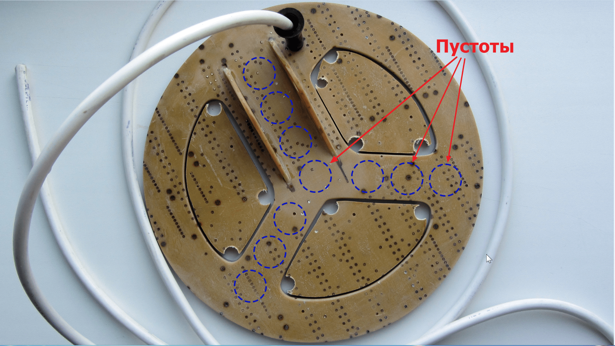
The voids inside the structure would have almost no effect on strength, but they would reduce the total mass by another 20-30 grams. Now, of course, it's too late to rush about, but I'll keep it in mind for the future.
Another way to simplify the design of the sensor is to reduce the width of the outer ring (where the wire turns are laid) by 6-7 millimeters. Of course, this can be done now, but so far there is no such need.
Finishing color
I found an excellent paint for fiberglass and fiberglass products - epoxy resin with the addition of a dye of the desired color. Since the entire construction of my sensor is based on bauxite, the resin-based paint will have excellent adhesion, and will lay down like a native.
I used PF-115 alkyd enamel as a black dye, adding it until the desired hiding power was obtained.
As practice has shown, a layer of such paint is held very firmly, and it looks as if the product has been dipped in liquid plastic: 

In this case, the color can be any, depending on the enamel used.
The final mass of the search coil together with the cable after painting is 407 g 
The cable separately weighs ~ 80 grams.
Examination
After our homemade metal detector coil was completely ready, it was necessary to check it for the absence of an internal break. The easiest way to check is to measure the resistance of the winding with a tester, which should normally be very low (maximum 2.5 ohms).
In my case, the resistance of the coil, together with two meters of the connecting cable, turned out to be around 0.9 ohms.
Unfortunately, in such a simple way it will not be possible to detect an interturn circuit, so you have to rely on your accuracy when winding. A short circuit, if any, will immediately manifest itself after the circuit is started - the metal detector will consume increased current and have an extremely low sensitivity.
Conclusion
So, I think that the task was completed successfully: I managed to make a very strong, water-resistant and not too heavy reel from the most junk materials. List of expenses:
- Fiberglass sheet 27 x 25 cm - free of charge;
- Fiberglass sheet, 2 x 0.7 m - free of charge;
- Epoxy resin, 200 g - 120 rubles;
- Enamel PF-115, black, 0.4 kg - 72 rubles;
- Winding wire PETV-2 0.71 mm, 100 g - 250 rubles;
- Connecting cable PVA 2x1.5 (2 meters) - 46 rubles;
- Cable entry - free of charge.
Now I am faced with the task of manufacturing exactly the same rogue rod. But it's already.
