Block sewer for electric cables. Laying of cables in the block sewerage using double-walled corrugated pipes of ZAO "dks". Album raw data
JSC "NIPI "TYAZHPROMELEKTROPROEKT" and
CJSC "DIELECTRIC CABLE SYSTEMS 1"
STANDARD ALBUM А10-2011
MOSCOW 2011
JSC "NIPI "TYAZHPROMELECTROPROEKT"
CJSC "DIELECTRIC CABLE SYSTEMS"
STANDARD ALBUM А10-2011 LAYING OF CABLES IN THE BLOCK SEWER WITH THE USE OF DOUBLE-WALL CORRUGATED PIPES CJSC "DKS"
OJSC "NIPI "TYAZHPROMELECTROPROEKT":
Director General of the Institute Chief Engineer of the Institute Head of PKO
G. A. Cherednichenko K. B. Shugarov
CJSC "DIELECTRIC CABLE SYSTEMS":
Chief Engineer
Senior Product Manager
MOSCOW 2011
Yin No. sub. Signature and date | Vzst inb. N
Table of flexible pipes
|
Dimensions, mm |
||
|
Rigid pipe table |
|||||||||||||||||||
|
|||||||||||||||||||
|
||||||||||||||||||||||||||||||||||||||||||||||||||||||||||||||
|
AZ format |
||||||||||||||||||||||||||||||||||||||||||||||||||||||||||||||
Yin N 8 vile! Signature and dota 1Vzam inb. fT
Detachable coupling Ф 110 mm (code 017110)
Locking parts with locks
Sealing sleeve made of thermoplastic rubber
The connector is used for mechanical detachable connection of pipes of the same size. Degree of protection at the connection point IP67 due to the sealing sleeve made of thermoplastic rubber.
|
Lukoyanob | |||||||||
|
Serdyushkin |
Pipe accessories | ||||||||
|
Komissarov |
dubusten CJSC DYuZ |
ROPROJECT |
|||||||
AZ format
Coupling
InV. N° authentic Signature and dota IResp. inbGTG
msrt table
|
Inner diameter, mm |
Size, mm |
||||
The coupling is used for mechanical one-piece connection of pipes of the same size, degree of protection IP40. When used in conjunction with sealing ring degree of protection IP55 is achieved.
A10-2011.07
Distance holder (cluster) single
|In6. N ° fl I Signature and date I Subm. inb. Ng
|
Single Cluster Table |
||||||||||||||||||||||||||||||||
|
||||||||||||||||||||||||||||||||
|
|
|||||||||||||||||||||||
|
AZ format |
Distance holder (cluster) double
|In6. N e fore I Signature and dota I Vzm. inb. No.
|
Clusterob dboynh table |
||||||||||||||||||||||||||||||||||||||||||||||||||||
|
||||||||||||||||||||||||||||||||||||||||||||||||||||
AZ format
|In6. N 8 fore I Signature and dota I Subm. inb. No.
|
Table of ternary clusters |
||||||||||||||||||||||||||||||
|
||||||||||||||||||||||||||||||
Distance holder (cluster) triple
|In6. N 8 vile I Signature and date | Vzam. inb. No.
|
Table of ternary clusters |
||||||||||||||||||||||||||
|
||||||||||||||||||||||||||
|
|
|||||||||||||||||||||||
|
AZ format |
Inb. № noqjil Signature and date | inb. No.
|
Table of brackets for single LAS |
||||||||||||||||||||||||||||||
|
|
Lukoyanov |
Cable structures CJSC "DKS" | ||||||||
|
Serchushkin | |||||||||
|
I, A * CHNO-ISSLGPSvA1GG "SKY<■проекшо-ко 1С1рук!орский TYAZHPROMELECTROPROEKT |
|||||||||
|
Komissarov | |||||||||
Profile C-shaped LAS 41x41 mm, 2.5 mm thick. Code 34024
[Inb. N ° mean | Signature and date | Vzam. inb. No.
Profile C-shaped LAS 41x41 mm, 1.5 mm thick. Code 34021
In5. N g nogjil Signature and date | Rem. uhB.~N^
Inb. Sub No. Signature and date | Sub. inb. No.
|
Designation document |
Name | |
|
Title page | ||
|
A10-2011.01 PZ |
Explanatory note | |
|
A10-2011.03TB |
Well Selection Table | |
|
A10-2011.04TB |
Current Cable Selection Chart | |
|
The choice of distances between the shelves of cable structures | ||
|
Dbusten pipe CJSC "DKS. Dimensional drawing | ||
|
Accessories for double-wall pipes CJSC ”DKS” | ||
|
Cable structures CJSC "DKS. Dimensional drawing | ||
|
The device of blocks from double-walled pipes. Construction | ||
|
Construction task for a block sewer. Example | ||
|
Well cable direct KGP and KP2. Construction | ||
|
Well cable corner KUL1 and KUSh. Construction | ||
|
Well cable corner KUGI and KUSH. Construction | ||
|
Well cable corner KU1-6 and KU2-6. | ||
|
Construction task | ||
|
Well cable angular KU1-4.5 and KU2-4.5. | ||
|
Construction task | ||
|
Well cable corner KU1-3 and KU2-3. | ||
|
Construction task |
|
Designation document |
Name | |
|
Well cable tee KT1-9 and KT2-9. | ||
|
Construction task | ||
|
Well cable tee KT1-12. | ||
|
Construction task | ||
|
Well cable krestoby KK1. | ||
|
Construction task | ||
|
Well cable krestoby KK2. | ||
|
Construction task | ||
|
Cable chamber for transition from block 6 to trench. | ||
|
Construction task | ||
|
Cable camera K Construction task | ||
|
Cable camera KK Construction task | ||
|
Necks of cable wells. Construction task | ||
|
Mortgage detail | ||
|
Intersection of the block with the pipeline. | ||
|
Construction task | ||
|
Intersection of a block with a heat probe | ||
|
Construction task | ||
|
Crossing a block with roads Construction task | ||
|
Laying cables 6 straight manhole Example | ||
|
Laying cables in a corner well Example | ||
|
Laying cables in a tee well Example | ||
|
Cable routing 6 in a cross pit Example | ||
|
Laying cables from a cable block in a trench. | ||
A10-2011C
Section 1-1
Inb. N°~nogji| Signature and date | Altern. inb. No.
|
Block type* |
Number of channels |
Size, mm |
|||
|
Horizontally |
Vertically | ||||
|
Designation |
Name |
Weight eg., kg | |||
|
Rigid pipe for | |||||
|
cable duct, Ф=110 | |||||
|
Mustard connecting for | |||||
|
pipes Ф= 110 | |||||
|
Code 025111...025113 |
Distance holder (cluster) | ||||
|
for pipes Ф=110 |
Section 2-2
1. See A10-2011.02 for requirements for a construction assignment.
2. Standard solution Made on the basis of the products of CJSC DKS 1.
|
|||||||||||||||||||||||||||||||||||||||||||||||||||||||||||||
|
AZ format |
|||||||||||||||||||||||||||||||||||||||||||||||||||||||||||||
1. Original album data
1.1. The initial data for the development of this album were:
- "Punched through the devices of electrical installations";
Building codes and passed SNiP 3.05.06-85 "Electrical devices";
Instruction IS 0001-2009-LU "Design, laying and installation of cable ducts based on flexible and rigid dubusten polyethylene pipes of CJSC DKS";
Standard album A6-92 "Laying cables for block sewerage" VNIPI Tyazhpromelektroproekt;
Other reference materials.
2.1. The album features:
Reference materials;
Construction tasks for blocks of pipes;
Construction tasks for cable wells and chambers;
Examples of cable routing in cable ducts
3. Scope
3.1. The materials of the album are intended for use when performing design and installation work on laying cables and block sewerage from corrugated dubusten pipes inside and outside buildings.
3.2. Laying cables in trenches and channels requires the opening of routes during repairs, replacement or additional laying of cables. Block sewer does not have this drawback.
3.3. In block sewerage, cables are protected from external influences (aggressiveness of soils, stray currents) and mechanical influences (passage of heavy vehicles, damage during repairs* of parallel above-ground and underground utilities).
gg
3.4. Block sewerage is used where the opening of cable routes is undesirable or Harmful (expensive coatings, squares and streets of cities, territories of unique objects, cultural institutions, etc.), in areas with a large number of communications, in areas with dense buildings.
4. BASIC PROVISIONS
4.1. For the manufacture of cable blocks, corrugated double-walled pipes manufactured by CJSC ”DKS” are used in the album.
4.2. Pipes allow you to bend the route in the horizontal or vertical planes when avoiding obstacles or crossing communications
An example of such a bypass is shown in Fig. A10-2011.26, sheet 2.
4.3. Unarmored cables with a lead or plastic sheath with a voltage of up to 10 kV with a cross section of up to 185 mm 2 are laid in the block sewerage, as if struck. If necessary, plastic-insulated wires and plastic- or rubber-insulated cables can be laid in it. In a plastic sheath with a voltage of up to 1000 V.
It is allowed to lay armored cables with an aluminum or lead sheath without an outer sheath of cable yarn.
4.4. Permissible continuous currents for cables laid in blocks are shown in drawing A10-2011.04TB
4.5. The cable block must have up to 15% of redundant channels, but not less than one.
4.6. The album contains construction tasks for cable wells and chambers. Well Selection Table is shown in Fig.
A10-2011.03TB.
|
Explanatory note |
||||||||||||||||||||||||||||||||||||||||||||||||
A10-2011.01 PZ
|
TYAZHPROMELECTROPROEKT |
||
4.7. The distance between cable wells should not be more than:
For cables with copper conductors with a lead sheath with a cross section up to: 50 mm 2 - 145 m, 75 mm 2 - 115 m, 95 mm 2 and above -108 m;
For cables with aluminum conductors In a lead or plastic sheath - 150 m;
For cables and wires with plastic and rubber insulation - 75 m;
For armored cables with an aluminum or lead sheath without an outer sheath of cable yarn - 50 m.
4.8. Cable wells are intended for installation of connecting, branch and locking fittings, as well as at the corners of the cable lines.
4.9. Cable wells with a length of 6 m (KP1, KU1...) should be used where it is possible to install a cable on cables with paper insulation.
Wells 4 m long (KP2, KU2...) In other cases
4.10. Cable wells and chambers should be constructed, as it struck on the impassable parts of the territories (lawns, sidewalks, etc.).
4.11. Cable chambers can be used: at the entrance of cables into buildings, at the transition of cables from a block sewer into a trench, with a small length and branching of cable duct routes, or when laying cables and pro-dV up to 500 V.
Couplings and other couplings should not be installed in the chambers, since this is due to the difficulty of opening the chambers. The floor slabs of the chambers can be covered with soil, covered with asphalt. The main purpose of the cameras is the convenience of installing cable lines.
4.12. For grounding of cable structures In the wells, round steel with a diameter of 6 mm is used, laid in a cable-free channel.
A10-2011.01 PZ
AZ format
1. These requirements, together with the drawings of the construction task, are the task of the design and design electricians for the execution of working drawings of the construction part of the block sewer.
Working construction drawings must be agreed with the organization that issued the construction task before they are transferred for construction.
2. For the manufacture of cable blocks, pipes and accessories for them manufactured by CJSC ”DKS” are used.
3. The laying depth of cable blocks in enclosed areas and in the floors of industrial premises is not standardized. In other cases, the laying depth is assumed to be at least 0.7 m from the planning mark or ground level.
4. Cable blocks must have a slope of at least 0.2% towards the well.
5. The type of base for cable blocks must be taken depending on the bearing capacity of soil and loads
In all soils, with the exception of floating, marshy and subsidence type II, it is necessary to provide for the laying of cable blocks along the leveled and compacted bottom of the trench on a sandy base 100 mm thick, and in silty, peat and other weak soils on an artificial base with tiered filling of gaps sand between the pipes.
On top of the block, a protective layer 300 mm thick must be made of soft local soil that does not contain solid inclusions (rubble, stones, bricks, etc.). In winter, the protective layer is made with unfrozen soil.
6. The necessary mechanical strength of the block sewer and its resistance to loads when crossing the route with heavy vehicles (railways, runways) should be provided with a concrete pad and filling the gaps with concrete mortar, and in special cases, laying reinforced concrete slabs on top of the blocks.
7. Installation of blocks from double-walled polyethylene pipes In the cold season, it is carried out at a temperature not lower than minus 30 °.
8. In areas where molten metals, high temperature liquids or substances that can destroy cable sheaths can be spilled, the construction of a well is not allowed.
9. Manholes of cable wells must be arranged in such a way that process water and oil do not get into the wells, and the drainage of soil and rainwater is also provided. Floors in wells must have a slope of at least 0.5% towards the catchment pits.
10. Manholes of cable wells must be closed with double metal covers. The bottom lid must have a locking device. Indoors, the use of a second lid is not required.
|
Requirements for the building part of the block sewer | |||||||||
|
TYAZHPROMELECTROPROEKT |
|||||||||
|
Komissarov | |||||||||
Well Marker 1
K-well
K- cross U-straight U-angle T- tee
R-right L-leby
1- length 6m
2- length 4m
9-overhang 90 6-overhang 60 4.5-overhang 45
3- turning angle 30
|
overcoming (rebounds) |
construction |
|||||
|
1.8...KP1-3.0 | ||||||
|
1.8... KP2-3.0 | ||||||
|
1.8...KUL1-9-3.0 | ||||||
|
1.8...KUL2-9-3.0 | ||||||
|
1.8... KUP1-9-3.0 | ||||||
|
1.8... KUP2-9-3.0 | ||||||
|
1.8... KU1-6-3.0 | ||||||
|
1.8 ... KU2-6-3.0 | ||||||
|
1.8 ... KU1-4.5-3.0 | ||||||
|
1.8 ... KU2-4.5-3.0 | ||||||
|
1.8... KU1-3-3.0 | ||||||
|
1.8 ... KU2-3-3.0 | ||||||
|
1.8... KT1-9-3.0 | ||||||
|
1.8... KT2-9-3.0 | ||||||
|
1.8...KT1-12-3.0 | ||||||
|
1.8...KK1-3.0 | ||||||
|
1.8...KK2-3.0 | ||||||
InB. No. vile! Signature and date | Altern. inB, NS
1.8; 2.1; 2.4; 2.7; 3.0 - depth b meters Example:
|
A10-2011.03TB |
|||||||||
|
well selection table | |||||||||
|
Serchushkin | |||||||||
|
TYAZHPROMELESTROPROEKT |
|||||||||
|
Komissarov | |||||||||
The choice of the depth of the well is determined by the difference in the marks of the cable block route (before and after the well).
KUL-1-9-1.8 - a well with a corner, left, 6 m long, overturning angle 90, 1.8 m deep.
AZ format
Block configuration
Current I o, A for cables
a l io-mil..x
Side 2 of 2
Cable wells allow laying cables up to 10 kV with single-wire conductors with a cross section of up to 240 mm 2 and installing cable boxes with protective covers 1250 mm long on them. The height of the wells does not exceed 2100 mm. Distinguish between direct wells, angular, branching, tee and cross (respectively with the output of blocks from three and four sides). Outside, the cable wells are closed with hatches, inside they are equipped with metal ladders or brackets for lowering people. The distance between the wells is taken no more than 150 m.
Cable wells: a - through passage; b - angular; in - T-shaped; g - cruciform; d - obtuse; e - Z-shaped
The dimensions of the cable wells should provide normal conditions for pulling cables with a maximum cross section of 3x240 mm 2 with a cable bending radius R = 25s?, replacing them if necessary, installing couplings with protective metal casings 1250 mm long.
Cable wells are made of brick or precast concrete of the following types: direct type through passage, angular - for changing the direction of block sewerage with rotation angles of 90, 120, 135 and 150 °, tee straight and with a rotation angle of 120 and 150 °, cruciform.
The slope of the well floor should be 0.003 towards the water collector. The grate of the water collector must be metal. The installation of embedded parts for cable structures is carried out during the installation of wells.
The necks (manholes) of cable wells must be round or oval and have double metal covers, of which the lower one must have devices for their removal. Round hatches are designed only for one-sided pulling of cables and must have a diameter of at least 700 mm, oval hatches are designed for double-sided pulling of long cables with a cross section of up to 185 mm 2 and have a width of 800, a length of 1800 mm. Cables with a cross section of 240 mm * and above should be pulled without a loop in one direction. Wells should be provided with steel brackets or a metal ladder for descent.
Due to the fact that cable wells are the most expensive part of block sewerage, it is recommended to use cable chambers when switching from block sewerage to trench sewage.
When making blocks from asbestos-cement pipes, the inner surfaces of the pipes and their joints must be lubricated with BN-IV bitumen diluted in kerosene (2 mass parts of bitumen and 1 mass part of kerosene). In dry soils, all outer surfaces of pipes and their joints should be covered with paint waterproofing in two layers, and in wet and water-saturated soils, waterproofing in two layers should be arranged.
For blocks of ceramic pipes for aggressive soils, the voids between the pipes must be filled with concrete, for non-aggressive soils - with concrete, but only at the junctions of the pipes, and the rest must be covered with sand or sifted soil.
When laying the block in parallel with pipelines, the distance between the pipelines and the nearest cable must be at least 250 mm, and when parallel laying with a heat pipeline, at least 2 m.
The constructed blocks before backfilling with earth must be accepted by the electrical installation and operating organizations. Block sewer, must comply with the project. The depth of cable blocks (counting from the top cable) must be at least 1 m at the intersection of streets and squares and 0.7 m in all other cases. In industrial premises and in closed areas, the depth is not standardized.
The route of the cable blocks must be straight. When crossing engineering structures, the route must be perpendicular to their axis. In some cases, a deviation from the right angle is allowed, but not more than 45 °, when the need for this is caused by the location of the place where the blocks enter the building or the presence of structures built on the route.
Each cable block must have 10% redundant channels, but not less than one channel.
If the block sewerage is made with deviations from the project, then when accepting the construction part for installation, the electrical installation organization must be transferred corrected as-built drawings. Deviations from the project must be agreed with the author of the electrical part of the project.
Backfilling of blocks is allowed only after their acceptance. Channels of cable blocks and pipes, exits from them, as well as their connection points, must have a treated and cleaned surface to prevent mechanical damage to cable sheaths both during pulling and under operating conditions.
The inner diameters of the holes (channels) of reinforced concrete blocks must be at least 90 mm, the inner diameters of the block sewer pipes - at least 100 mm.
Cable blocks must have a slope of at least 0.2% towards the wells.
The smallest clear distances between block sewer pipes laid directly in the ground must be the same. as for cables laid without pipes.
When entering blocks into buildings and cable structures (tunnels, collectors, basements, etc.), measures must be taken to prevent penetration through pipes or openings of water, gas and small animals from trenches into buildings and structures.
On fig. a general view of the block cable duct is given.
When laying the cable in the block, it is necessary to ensure the complete watertightness of the pipeline. To do this, the following measures are taken: after installation, the pipeline is tested with air or water pressure; sealing seals are arranged at the exit points of the cable from the pipeline (filling with bitumen yarn, etc.)
To tighten the cable into the channel of the block, it is necessary to clean it from the concrete solution when joining the blocks and construction debris. This is achieved by pulling a rope through the channel with a winch attached to it in the form of a steel control cylinder and ruffs. The outer diameter of the control surface of the cylinder should be 15 mm less than the diameter of the channel, and the diameter of the ruff - 6 mm more than the diameter of the channel. The channel cleaning scheme is shown in fig. To do this, a steel rope is attached to one end of the steel wire previously drawn into the channel and pulled through the channel, after which a control cylinder with ruffs is attached to the second end of the rope. Guide rollers are fixed in the well (closest to the winch), through which the stretched rope is passed, and, having attached it to the winch rope, the channel is cleaned. When cleaning the route, a steel rope is attached to the last ruff, which is simultaneously pulled into the channel for subsequent cable pulling. It is recommended to tighten the wire into the channels of the blocks during the construction of cable ducts. The tightening of the wire into the blocks of the completed sewerage system on sections of the route up to 50 m long is carried out by directly pushing a round wire with a diameter of 4 ... 5 mm with a bent end so that it cannot rest against the walls of the channel.

Ruff for channel cleaning 

Block cable duct: 1 - exit from the well; 2 - passing well; 3 - branching well; 4 - corner well
In sections longer than 50 m, the steel rope should be tightened in one of the following ways: a) by pushing the wire from the two ends of the pipes simultaneously with a hook previously made at each end, when they meet in the pipe, the ends of the wires are linked, and the wire is pulled out from one side so that it comes out place of adhesion of the wires; b) with the help of coupling or screwing rods (rods); c) with the help of pneumoducters pulling a nylon cord with a diameter of 20...30 mm at an excess pressure of compressed air of 600...700 kPa.
For laying in a block sewer, unarmoured cables with a bare lead sheath of the SG and ASG brands, as well as cables with a bare PVC sheath of the VVG, AVVG, VGR and AVRG brands, should be used. In sections of blocks up to 50 m long, it is also allowed to lay armored cables in a lead or aluminum sheath without an outer cover of cable yarn with painting of the armor for corrosion protection with bituminous varnish of the brand BT-577 according to GOST 5631-79. 
Block sewer cleaning scheme: 1 - cable drum; 2 - rope for cable tightening; 3 - rope for channel cleaning; 4 - control cylinder; 5 - roller; 6 - block channel; 7 - ruff; 8 - spacer roller

Pneumatic device for tightening the cord into the block: 1 - pipe; 2 - piston; 3, 4 - nozzles; 5 - fitting for an air hose;
b - coil with cable or nylon cord
Cable grades for each specific case are determined by the project When pulling the SG brand cable into blocks, with the rope fastened to the cable sheath with a stocking, the total length of the block channel under the conditions of maximum permissible tensile force should not exceed 145 m for cables with a cross section of up to 3x50 mm 2, 115 m - section 3x70 mm 2, 108 m - section 3x95 mm 2 and above.
The cable is pulled into the block channel with a cable, fixed at the end with a wire stocking or cable clamp.
The wire stocking (a) is put on the end of the cable and, in a section not less than 500 mm long, is firmly fixed with one or more bandages made of soft wire with a diameter of 1.5 mm. The bandages are applied over the winding of 2...3 layers of resin tape.
Tightening the cable with a wire stocking has disadvantages, the main of which are: a significant amount of time to fix the stocking on the cable; the possibility of slipping of the stocking from the shell; danger of rupture of the cable sheath in the immediate vicinity of the place where the stocking is applied, especially with large lengths and cross-sections of the cable.
More perfect is the method of fastening the cable with a conical clamp (g) consisting of a steel head with a special hole for the cable, a conical sprocket, along the side surfaces of which there are three sectoral recesses at a distance equal to 1/3 of the circle, an external cone and a housing designed to protect bare conductors of the cable from mechanical damage.
Cables of large cross-sections and long lengths are pulled into the channels only with a steel clamp fixed directly to the cores at the ends of the cable.
If it is impossible to pull through the cable through two or more sections, then the cable can be pulled from the intermediate well to both sides of the route, provided that the dimensions of the hatch allow a cable loop to be lowered into the well at the end of the pull, observing the permissible bending radius.
In this case, the cable drum is installed at the intermediate well and the cable is pulled over a longer section of the route. Then the cable is wound from the drum and cut off according to the measurement to the length of the second section (with an allowance for cable connection) and laid out in loops on the ground. Having previously fixed the end of the cable to the rope pulled into the channel of the block, it is pulled in the second section of the route, carefully observing that when the pull is completed and the loop is lowered into the well, the bending radius of the cable is not less than the permissible one.
In the process of tightening the cable, to reduce friction and mechanical wear, the cable surfaces are lubricated with grease or grease with a layer thickness of 2 mm. It must be ensured that the cable in the intermediate well is not subjected to excessive force.
The end of the cable, cut off at the drum and lowered into the well, must be sealed. On both sides of the couplings (at a distance of 1 m from the coupling), the ends of the cable are fixed on the supporting structures of the well. In places where the cables approach at a distance less than the permissible distance, it is necessary to put rings cut from asbestos-cement pipes on the cables with a cut in them along the axis of the slots, equal in width to 1.1 cable diameters.
It is recommended to pull the cable at a speed of 0.6 ... 1 km / h and, if possible, without stops, in order to avoid large pulling forces when starting the cable.
After pulling, the cable should be laid in the well on the supporting structures, its ends should be sealed, and elastic gaskets (for example, sheet asbestos) should be laid in all places where the cable exits the block channels to protect the sheath from abrasion.
Couplings in the well after their installation must be placed in a protective fire casing.
At the inputs of blocks into buildings, tunnels, the holes in the blocks after laying the cables must be sealed with fireproof and easily pierced material.
The maximum total length of the block channel for cables of the ASG brand with a cross section of 3x95 mm 2 and above should not exceed 150 m.
The maximum allowable tensile forces for cables of the SG and ASG brands with fastening of the rope for the cores, as well as the required forces for pulling 100 m of the cable through the block sewer are given in Table.
The maximum permissible tensile forces of cables of the VVG, AVVG, VRG and AVRG brands with a rope fastened to the cores should be taken with a coefficient of 0.7 - for copper conductors, 0.5 - for aluminum conductors made of solid aluminum, 0.25 - for aluminum conductors made of semi-solid aluminum.
To control the tensile force, a dynamometer or other control device is installed on the winch.
The cable is drawn in the area between two adjacent wells according to the scheme shown in Fig. install a detachable funnel into the inlet of the block channel, store the rope through the rollers, attach it to the winch rope and start tightening the cable.
Through pulling of the cable in two or more sections, without cutting it in intermediate wells, is possible provided that after pulling in the wells the necessary length of cable is created for laying it on supporting structures.

Scheme of pulling the cable in one section: 1 - drum with cable; 2 - corner roller; 3 - cable; 4 - detachable funnel; 5 - rope; b - rope roller; 1- installation for tension control 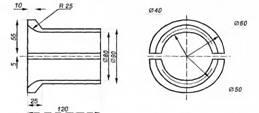

Scheme of arrangement of mechanisms and devices for laying cables in blocks: 1 - drum with cable; 2 - corner rollers in the input and output wells; 3 - linear rollers; 4 - corner rollers in intermediate wells; 5 - traction winch; K1...K4 - block sewer wells
To pull the cable, in accordance with the project for the production of work, it is necessary to first install all the necessary angular and guide rollers both in the extreme and in the intermediate wells.
The figure shows an approximate route and a diagram of the arrangement of mechanisms and devices in it.
The maximum allowable tensile force for the cable cores in the channels of the block is determined as P, equal to 1 / 6P (the ultimate strength of the sum of the cable cores, which is taken from the calculation of 26 for copper cores, and 16 kg / mm for aluminum ones).
The calculated tensile force of 1 m of cable with mass Q (kg) with a friction coefficient a = 0.6 is calculated by the formula:
P = 0.6Q
To pull the rope block of the drive winch into the channels, a steel wire with a diameter of 4 ... 5 mm is used, which was laid during the construction of a block sewer. If such a wire was not laid in the channel, it is drawn in sections up to 50 m long by directly pushing it into the inlet
The maximum allowable length of the cable pulled into the blocks using a wire stocking is given in table.
The maximum allowable length of the cable pulled into the blocks using a wire stocking, m
Block cabling has significant disadvantages:
- high cost of construction and maintenance of blocks and wells;
- the impossibility of maximum use of the cross-section of conductors of cables according to the permissible current density due to poor cooling conditions;
- the complexity of maintaining and repairing cables (if they are damaged inside the blocks, it is necessary to replace the entire section of the cable between the wells).
On the territory of energy-intensive industrial enterprises with more than 20 cables running in one direction, laying in tunnels is used. Such laying ensures reliable operation of cable lines, but has the highest cost of the construction part.
For more reliable (compared to laying in a trench) protection against mechanical damage, cables are laid in cable blocks. A cable block is a cable structure with pipes (channels) for laying cables in them with wells related to it. Typically, a cable block consists of several asbestos-cement pipes, the inner diameter of which is 1.5 times the diameter of the cable. Laying cables in blocks is recommended at the intersection of the route with railways and roads, when laying in soils that are aggressive with respect to the cable sheath, if it is necessary to protect cables from stray currents, etc.
Picture. Cable block from asbestos-cement pipes in dry (a) and wet (b) soils: 1 - sand or sifted soil; 2 - pipes; 3 - wooden gaskets; 4 - concrete pad; 5 - waterproofing.
In places where the direction of the route changes or the depth of the blocks, as well as on straight sections of great length, cable wells (chambers) are made. There are also cable boxes in the wells.

Picture. Block cable duct scheme: 1 - cable block; 2 - passing well; 3 - branching well; 4 - corner well.
Distinguish between direct wells, angular, branching, tee and cross. Cable wells are made of brick or precast concrete structures. Outside, cable wells are closed with hatches, inside they are equipped with cable structures (for laying cable boxes on them), water collectors in the floor, closed gratings, as well as metal ladders or brackets for lowering people. When installing blocks for moisture drainage, they are laid with a slope towards the wells of at least 0.2% (i.e. 0.2 m per 100 m of the route).

Picture. Cable wells: a - straight, b - angular, c - branching tee, d - branching cross; e - obtuse; e - Z-shaped.
The cable is drawn between two wells as follows: a steel rope of the UZK type is pulled into the block channel, corner rollers are installed, the cable is attached to the rope, a funnel is installed in the block channel inlet to protect the cable from mechanical damage during cable pulling, the cable is pulled in the channel with a given pull force.
Autonomous sewerage of a country house should be efficient and inexpensive. Wastewater is diverted to storage tanks made of iron barrels, biological treatment plants made of plastic or wells made of reinforced concrete rings. You can also arrange a septic tank from blocks that are affordable and easy to install. The technology of work is extremely simple, almost every private trader can handle it with his own hands.
There are many designs of autonomous sewers. They can have a different number of chambers, be with a sealed and draining bottom. If you choose a waterproof option, then sewage from such a container will have to be regularly pumped out by a sewage machine. It is better to opt for a structure with drainage or an infiltrator.

Autonomous block sewerage is cheap and easy to install
From the blocks you can make a septic tank:
- Single-chamber (classic cesspool or wastewater storage).
- Two-chamber - with separate tanks for clarification and fermentation.
- Three-chamber - with an additional drainage well.
The cesspool has a low level of wastewater treatment. The second option allows you to clean wastewater by 60-70%, and the third - by 90%. But in a similar sequence, the space occupied by the sewer in the adjacent area also increases.
Advice! A cesspool should be installed only in summer cottages, where there are few drains. For country houses, it is better to equip more productive treatment facilities with two or three sections.
If the chambers in the septic tank are sealed, then another reservoir with drainage, an infiltrator or a filtration field will have to be equipped nearby. And these are additional areas that are not recommended for use for beds or planting trees due to high soil moisture.

Septic tank scheme with one and two sealed chambers
Most often, autonomous sewage from blocks is made in the form of a single structure, divided in the middle into two chambers. The first is sealed, and the second - with a drainage cushion instead of the bottom. First, the effluents are clarified in tank No. 1, and then in tank No. 2 they are subjected to bottom post-treatment (they are drained into the ground through gravel).
From the foundation blocks, you can make a non-standard septic tank with a different number of sections inside or with separate tanks. Block masonry allows you to realize a lot.
Selection of blocks for autonomous sewage
On sale there are many blocks that are different in purpose and material, but not all of them are suitable for installing a septic tank. Here you should choose wisely so that the building material endures the aggressive effects of wastewater for many years and does not collapse.
- foundation made of heavy concrete with FBS marking;
- sand-concrete without cavities inside.
The first should be taken only factory-made. Handicrafts are of poor quality with voids; they will not last long in the ground. And sand concrete blocks can be made independently. It is only necessary to prepare the forms, and then carefully compact the concrete mixture into them. Essentially, both options are identical. But factory ones are stronger, and home-made ones are much cheaper.
Only foundation and sand concrete products made of heavy concrete have sufficient strength, frost resistance and moisture resistance so that partitions from them do not collapse in the ground. Hollow gas and foam concrete is not suitable for sewers.

Making sand concrete blocks with your own hands
Important! It is not recommended to use blocks made of cellular concrete, filled with slag or expanded clay, as well as with steel reinforcement for an autonomous sewerage device. All of them extremely poorly “get along” with moisture and will not last long.
The blocks must be made of cement grade M300 and above (corresponds to concrete B 22.5 and above). Other options are not strong enough and resistant to water for laying the walls of the treatment plant in the ground.
Calculation of the volume of a septic tank
Sanitary and building codes recommend that the size of an autonomous sewage system for a private house be selected at the rate of 600 liters for each person permanently residing in the cottage. This is two hundred daily liters multiplied by three days, which should be more than enough.
The indicated figures refer to the volume of the primary chamber, into which sewage flows immediately from the dwelling. The second and subsequent tanks can be made one third smaller. However, in practice, both sections of the septic tank from the blocks are constructed of the same size. This makes it easier to lay and calculate the amount of materials.

Examples of calculating the volume of a septic tank
Placement of a septic tank on the site
The place on the site for autonomous sewage is selected according to the following rules:
- The distance to drinking wells, reservoirs and wells must be at least 50 m.
- The septic tank is removed from the foundation of buildings by 4–5 m.
- To underground utilities and roads - a distance of 5 meters.
- There should be at least 3 meters to the beds and green spaces.
Compliance with these rules helps to avoid epidemics. It is impossible to completely eliminate the overflow of drain tanks with the subsequent release of sewage to the surface of the earth, therefore it is so important to leave a sanitary zone around the external sewage system.

Technology installation of a treatment plant made of concrete blocks
The sealed bottom of an autonomous sewage system is made of a reinforced concrete slab or by pouring a monolithic concrete base. The first method involves ordering a tap, and when using the second, you will have to wait a couple of weeks until the mixture hardens to the desired condition.
Necessary materials
To make a do-it-yourself septic tank from blocks, you will need:
- sewer manholes for each section;
- plastic pipes for overflows between compartments and ventilation riser;
- fittings for the slab at the base and the monolithic roof from above;
- cement (not lower than M300) and sand with water;
- bitumen-based waterproofing mastic;
- solid concrete blocks.
Advice! In depth, the septic tank of the external sewage system is recommended to be done within 1.5–3 meters. So it will be easier to maintain it, and it will take up less space.

A septic tank with two chambers is the most popular option
Construction stages
The construction of a two-chamber sealed septic tank from blocks is carried out in eight stages:
- Pits are dug for the size of an autonomous sewer with an indent on the sides of 25–30 cm.
- At the bottom of the pit, a sand and gravel cushion 15–20 cm thick is formed under the bottom from a finished reinforced concrete or poured slab.
- A concrete base is laid or poured.
- Blocks are being laid along the perimeter of the walls and in place of the partition in the middle.
- Block walls from the inside and outside, as well as the base are covered with bituminous mastic.
- A cover in the form of a monolithic plate with hatches is mounted on top.
- Ventilation and thermal insulation made of foam plastic are equipped (if necessary).
- The treatment plant is backfilled with earth.
When laying the blocks, an overflow is inserted into the bulkhead, in the wall, on the one hand, the sewer pipe is entered from the house, and on the other, the outlet to the drainage. If the second section should be with a draining lower part, then instead of a solid slab under the walls, a concrete foundation should be made, and a gravel and sand drainage should be arranged in the middle.
The overflow between the chambers is done at a depth of 50–60 cm from the septic tank lid. The input must be above the output. Pipes are laid with a slope of 2-3 degrees from the house, drains in the entire sewer system move by gravity.
Video: installation of autonomous sewage from foundation blocks
The technology of laying the walls of a septic tank from blocks with your own hands is extremely simple. Even a novice master will cope with this matter. The main thing is to carefully perform waterproofing so that untreated water does not seep into the ground.