Do-it-yourself inductive proximity sensor. Practical schemes for switching on sensors. Functions and principle of operation
Sensors for automatic devices of electronic equipment are the most important elements in electrical circuits. Sensors widely known to radio amateurs are used everywhere in professional industrial and non-professional equipment made by radio amateurs themselves. For example, a shock sensor in car alarms, or a noise sensor in acoustic devices, or an IR radiation sensor in devices for remote control of parameters. The options for sensor designs are endless. For example, a roll (or shock) sensor in a car alarm can be made with the same efficiency in several different ways. The sensors themselves are only part of the electronic circuit, so let's not forget that the reliable operation of the entire device also depends on the control circuit. What is a sensor?
There are many definitions, but the simplest is a device that changes its state depending on external influences. Below we will consider several options for sensors that can be made at home with your own hands without large time and financial costs. These sensors send single pulses or bursts of pulses (contact bounce) to the electronic control device, depending on the impact on them.
At present, the radio-electronic industry offers radio amateurs industrial versions of sensors, it would seem, for all occasions - even Geiger counters that register radiation have become available. The following material is relevant due to the high retail cost of most industrial sensors and is aimed at encouraging the creativity of a radio amateur in domestic and "field" conditions, when it is possible to manufacture sensors on their own, without losing their quality.
Mechanical sensors
On fig. 3.28 shows a variant of the manufacture of a flat mechanical sensor. By mounting one or more of these sensors under the carpet, linoleum, or under the wallpaper, it is possible to control the lighting, for example, in a hallway, without being noticed.
When you press your foot on the plane of the sensor (or press your hand on a certain place on the wall of an apartment, office), the foil contacts close, and the impulse goes through the connecting wires to the control circuit. The sensitivity of the sensor is high - it reacts even to a small load.
Rice. 3.28. Mechanical sensor design
As can be seen from the figure, a cardboard with a hole cut inside is superimposed on a dense foil, and another layer of foil is superimposed on it. Thin flexible conductors are carefully soldered to the conductive foil (dense paper-based foil is quite suitable). The entire resulting "sandwich" is then laminated. As a material for lamination, a plastic folder-pocket for papers or school supplies is used - it must be cut to the size of the sensor, put foil and cardboard inside and iron it through a rag. You can just glue the sensor with tape. If the control circuit uses noise-immune elements (MOSFETs or microcircuits), the length of the connecting wires from the sensors to the circuit can be several meters. If more distance is required, then bus amplifiers and level converters on microcircuits are used (for example, on elements K561PUZ, K561PU4, K561LP1, K561LN2 and others). If the sensor is made in several layers, alternating the conductor and the dielectric, then the resulting “thick sandwich” can be used as a force sensor (pressure) - that is, as a sensor for weighing. There are many options for using such a sensor; its feature is the possibility of easy masking. The flat sensor is reliable, durable and described in detail by the author in several developments of automatic household devices.
Acoustic sensors
On fig. 3.29 and 3.30 there are two sensitive circuits that perform the functions of an acoustic sensor that generates series (bursts) of pulses under sound exposure that is different from a quiet acoustic background. The operational amplifier circuit (Fig. 3.29) uses a piezoelectric element as an impact sensor.
Rice. 3.29. Acoustic sensor built on the op-amp
This option has been repeatedly published in combination with other types of OS and therefore it does not claim to be original. The primer ZP-22 was used as a piezoelectric element, and due to relative sensitivity - it reacts only to shocks - it is not very effective, but it can be successfully used in security devices, for example, for protecting windows. To do this, the capsule must be securely glued to the glass and the sensor will produce single pulses when it hits the glass. The larger the glass area (protected area) - the more sensitive the sensor. It can be used to protect from the side of external glasses and showcases in stores. The greater the resistance of resistors R4 and R2 at the input of the comparator, the more sensitive the circuit. From the output of the comparator (pin 6), the pulse goes to the key or forming circuit. Capacitor C1 (K50-24) filters power supply noise.
On fig. 3.30 shows a more sensitive, though more old-fashioned, version. As BM1, any carbon microphone from old telephones (MK-10 and similar) is used. The transistor amplifier is assembled according to the series amplification scheme in such a way that the gain of the second stage is twice that of the first, and so on. In the figure, we see a three-stage amplifier, which allows using this circuit as an ultra-sensitive one, however, if such sensitivity is not so necessary, you can get by with only one stage on a composite transistor. The amplifier is operable within a wide range of supply voltage of the circuit. From the collector of the last transistor, bursts of pulses are fed to a key or pulse sequence-forming circuit (for example, a single vibrator). The gain is effectively regulated by the resistor R1 (the greater its resistance, the more sensitive the circuit) and, to a small extent, by the resistor R6. As you know, such microphones contain carbon powder, which is very sensitive to concussions and sound waves, it changes the resistance of the microphone to direct current. These pulses are captured by the amplifier on transistors VT1-VT4. A negative feature of the circuit is its inertia, due to the properties of carbon microphones. But for many amateur radio developments, such a sensitive circuit is almost indispensable in its simplicity and efficiency. Positive qualities - ease of manufacture, non-criticality to reverse switching on and power supply voltage drops, reliability. Conductors from the microphone to the electrical circuit must be kept to a minimum length. Transistors can be used any of the KT3107, KT361 series. In the author's practice, the device shown in Fig. 3.30 has been successfully and consistently used as a sound sensor for supplying air to fish in an aquarium. The microphone, together with the sensor circuit, is installed in a compact plastic case, which is securely attached to the aquarium wall in such a way as to ensure a snug fit of the working surface of the carbon microphone to the glass. Practice has shown that any movement behind the wall of the aquarium, even a small fish near the microphone-sensor, and even more so when the fish floats to the upper edge of the water for air, is captured by the sensor and it gives out a pack of pulses. The carbon microphone changes its impedance depending on external acoustic influences. This change is then sensed by the transistor amplifying circuit. The number of pulses in a pack is proportional to the strength of the impact of the sound wave on the microphone. The impulses are converted by the control circuit, and the compressor is automatically turned on for 1 ... 2 hours (time determined by the additional timer).
This sensor can also find other applications, such as an acoustic sensor that reacts to conversations in the room and turns on the backlight. If the body of the device together with the microphone is mounted on the floor, the circuit will notify of the approach of a person long before he approaches the sensor. Since the steps of a person on the floor, as practice shows in city apartments, affect its surface and are transmitted over a long distance. Thus, there are a lot of options for using such a sensor.
Inductive sensor
On fig. 3.31 shows a simple sensor that responds to magnetic induction. When a small current appears near the winding of the AND coil (for example, in the wires of a communication line), it is induced in the coil and transmitted to the amplifying stage on a composite transistor. The amplifier for this circuit can be of any configuration, with a large gain. An alternating voltage induced in coil I is removed from the positive lining of capacitor C2. If a magnetic antenna is used as a coil, a device can be obtained that responds to
Rice. 3.31. Amplifier for induction sensor
radio waves of a certain length, that is, to control the radio. The sensitivity of the circuit is regulated by the resistor R1, which sets the bias to the composite transistor.
The greater the resistance of the variable resistor, the more sensitive the circuit. For the optimal amplification mode (since the supply voltage of the circuit can vary significantly), the value of the resistor R2 is selected so that the current consumed by this node from the power source is within 2 mA. In practice, the sensor picks up an alternating current of 50 mA in wires up to 5 cm away. The length of the wires from the L1 coil to the input stage of the circuit should be kept to a minimum to eliminate interference.
The coil is wound with PEV or PEL wire with a diameter of 0.1 ... 0.15 mm in bulk and contains 2500 turns on any suitable cardboard, wooden or plastic frame with a diameter of 8 mm. A core made of ferrite grade 600 - 2000NN is inserted inside the frame. The length of the frame corresponds to the length of the core and is in the range of 25…40 mm.
current sensor
The design of the device is shown in Figure 3.32.
The sensor is a reed switch with a wire with a diameter of 0.08 ... 0.1 mm wound along the length of its glass body. Bulk winding (300-400 turns) - depending on the purpose of the sensor. When an electric current flows through the winding of such a sensor, the reed switch closes (opens) its contacts under the influence of magnetic induction, switching the peripheral circuit. Based on this sensor, a radio amateur can independently make a "current relay" by connecting one of the contacts of the reed switch to the end of the winding, as shown in fig. 3.33.
Immediately after switching on, the current flowing through the load creates a voltage drop across the winding L1. The voltage drop across the winding is directly proportional to the current in the circuit. The induced voltage will create a small electromagnetic field, which will be sufficient to affect the contacts of the reed switch, which will block the electrical circuit. When the load is de-energized (or the current in its circuit decreases, which can happen for very different reasons), the voltage drop across L1 will decrease, the magnetic field will decrease, and the reed switch contacts will open. The sensitivity of such a sensor depends on the number of turns L1 and the current strength in the circuit. The current relay, like the electromagnetic sensor, has many applications in radio engineering structures.
Low current sensor
Rice. 3.36. optical sensor
parallel to the transmitter and at an angle to it are photodetectors (block 2), also facing into space. In the absence of a reflective object, the energy emitted by the LED is dissipated without reaching the sensitive surface of the photodetectors. When an object appears within the active radiation range, the reflected light beam is captured by one or more sensors-receivers, as a result of which a pulse is sent from the photodetector to the control circuit. The distance from the signal emitter to the receiver (sensor) in the radiation plane should not exceed 4 ... 5 centimeters. However, if a mirror surface (even without a focusing lens) with a radius of curvature of 50–80 mm is used as a reflecting object, then the device can effectively operate at a distance of up to 25 cm from the reflecting object.
Based on this principle, a special sensor was created and tested in the life support system of aquariums and as a rain sensor for cars. Consider the operation of the node (the schematic diagram is shown in Fig. 3.36, b) using the example of an aquarium. The sensor (optocoupler AORS113A - an optocoupler with an open optical channel, in this scheme, its emitting LEDs and receiving photoresistors are connected in parallel) is mounted on the outside on one of the walls of the aquarium and the working surface is facing inside the aquarium. The anodes of the emitting diodes inside the optocoupler housing are combined and have a common pin 8. The AOP113A and AORS113A case is metal, with sixteen pins, based on a planar-type ceramic substrate, with a glass window. This makes it easier to mount to a flat controlled surface.
The difference between AOP113A and AOP113A is that AOP113A contains two identical transceivers (similar to one in AOP113A). The AORS113A optocoupler allows you to control two coordinates, respectively, and turn on differential photodetectors in series or in parallel.
In large aquariums (more than 60 liters), there are some difficulties with changing the water. Therefore, compressors are installed there to filter, purify water and constantly supply air to the water area. Water in large aquariums is replaced partially, and completely very rarely, in case of emergency. As a result, various organic deposits accumulate on the bottom and on the walls of the aquarium, polluting the water. In some cases, grass begins to bloom inside the water area and the water completely loses its transparency. For responsible owners, this is unacceptable. The original sensor considered here practically does not reflect radiation in the case of clean aquarium walls and clear water, and begins to reflect the beam if there is contamination. The impulse from the sensors is fed to the parameter control circuit (implemented on a composite transistor), then when power is applied to the load (alarm device), the latter signals the contamination of the aquarium with a sound. The control scheme should provide for a delay in the alarm signaling (a timer for several minutes) in order to exclude false alarms in the event of fish appearing within the active zone of the sensors or, for example, snails crawling. Practice has proven that living organisms in an aquarium are not harmed by a small radiation from the sensor. Rather, we can state the opposite fact - fish often appear in the working area of the sensors and are keenly interested in what is happening.
The principle of operation of the rain sensor for a car is similar to the one above. The sensors themselves (emitters and receivers) are connected to the control circuit by shielded conductors of the shortest length. The rain sensor actuator is designed to close the circuit of automotive electronics - the contacts of the wiper switch. The car does not need a delay to turn on the load devices. At night, in the dark, the device behaves stably. The sensitivity of the device is adjusted only once when installed on a car window to eliminate false positives from the solar radiation spectrum in clear weather. The power supply of the circuit is stabilized, it can be in the range of 10 ... 18 V. If the accuracy of the operation of the circuit is not fundamental, then any car relay for a voltage of 12 V can be used as a load.
The difference with the previous version consists in attaching the case with the device to the windshield of the car (from the inside). In clear weather, constant radiation freely passes through clean glass and is scattered in space. During rain, the glass from the outside is polluted with raindrops, which slightly reflect the rays. The reflected signal, accordingly, changes the resistance of the photoresistors in the case of the optocoupler with an open optical channel. This leads to a change in the mode of the composite transistor and the appearance of a current pulse at the output. As in the first case, photodetectors (photoresistors) are connected in parallel (their total resistance decreases faster when exposed to light - the node sensitivity increases). When there is no reflective signal, the total resistance of the photoresistors of the optocoupler is high, about a hundred kOhm. At the output of the circuit, the voltage tends to zero relative to the negative pole of the power source. The reflected light radiation will reduce the total resistance of the photoresistors and open VT1, VT2. At the output of the circuit, a high level voltage will appear, almost equal to the supply voltage. The sensitivity of the circuit is adjusted by a variable resistor R1, which should be selected with a linear characteristic. From the circuit output, a control signal can be applied to a comparator that compares the base voltage with the input voltage (assembled according to any standard circuit, for example, on K521SAZ). The comparator at its output will give a constant positive signal when the voltage at its input changes. The signal from the output of the comparator through any transistor switch will turn on the executive relay, which will close the alarm (load) circuit with its contacts.
A few words about mounting to the aquarium wall. The transparent window of the optocoupler housing is mounted to the glass with instant glue, while making sure that the glue does not get on the working surface of the optocoupler. Instead of AORS113A, two AOP113A devices can be used (in Fig. 3.36, c, the pinout and the difference between these optocouplers are shown). They have similar electrical parameters. The use of only one element from a pair will not be slow to affect the operation of the entire circuit in the direction of reducing sensitivity.
When using the circuit as a rain sensor for a car, the following fact must be taken into account. The device works well in the temperature range of 0 ... 50 ° C, so in winter, if the car is not put in a warm garage at a negative air temperature, at the first moments of the car’s movement, until the temperature in the cabin rises to zero degrees, the rain sensor may not respond correctly to external factors.
Fire sensor
In amateur radio practice, simple and reliable devices are popular - sensors that respond to changes in any input parameters. One such device is shown in Fig. 3.51 scheme, responsive to increase .......
Photo sensors and electronic devices implemented on their basis that control various household appliances have long been popular among radio amateurs. It would seem that it is already impossible to find anything new in the circuit design for such devices. That…….
Photoresistors are called semiconductor devices, the conductivity of which changes under the influence of light. Single crystal photoresistor Fig. 2.2. Single crystal photoresistor Film photoresistor 2.3. Film photoresistor Fig. 2.4. The inclusion of a photoresistor in a constant circuit .......
To ensure the normal operation of the engine, many mechanisms and controllers are used to perform different functions. One such device is the inductive sensor. What kind of controller is this, what is its principle of operation, what types of devices are there? We will talk about this below.
[ Hide ]
Characteristics of inductive transducers
An inductive sensor or is a non-contact device designed to control the position of an object made of metal. This is important because the device can only be sensitive to metal.
Functions and principle of operation
The principle of operation of the device is based on changing the amplitude of oscillations of the generator device built into the controller when a certain metal object is introduced into the active zone. Accordingly, the use of the device is possible only with these types of objects. When voltage is applied to the limit switch, which is located in the sensitivity zone, a magnetic field appears. This field contributes to the formation of eddy currents, the influence of which is reflected in the change in the amplitude of oscillations of the generator device.
As a result, such conversions contribute to the appearance of an analog output pulse, the value of which can be different depending on the distance between the controller and the object. The inductive displacement sensor plays a very important role for assemblies that are used to track changes in the location of metal objects. Thanks to the controller, it is determined whether this or that object is located correctly or not. In the event that the object is not where it should be, the control system will have to take all necessary actions in order to ensure the normal operation of the device.
As for the controller device, the device consists of the following elements:
- A generator unit designed to generate an electromagnetic field, which, in turn, is used to create an activity zone with an object.
- Amplifying device. Used to increase the amplitude value of the pulse so that the signal can reach the desired parameter.
- Schmitt trigger. This element is designed to provide hysterthesis when switching the device.
- A diode element that indicates the state of the controller. Also, the LED allows you to provide the most optimal control of the functioning of the device and indicate the promptness of the settings.
- The next element is the compound. Its purpose is to protect the device from moisture ingress into the case, as well as dirt and dust, which can lead to breakage.
- The body itself. The controller housing is designed to ensure the installation of the device, as well as its protection from all kinds of mechanical damage. As a rule, the body is made of brass or polyamide, and it is also equipped with all the necessary fasteners for fastening (the author of the video is the Lty D channel).
Controller types
Systems with an inductive sensor can use different devices that differ from each other in the following parameters:
- The design of the device, as well as the type of case, which can be rectangular or cylindrical. As for the material from which the case itself is made, it can be either metal or plastic.
- If we are talking about cylindrical parts, then they can have different body sizes. As a rule, case diameters are 12 and 18 mm, but other devices can be found - 4, 8, 22 mm, etc.
- The next parameter is the working backlash of the device, which is the distance to the steel plate of the controller. For small controllers, this figure is from 0 to 2 mm, for controllers with a diameter of 12 and 18 mm, the operating gap should be 4 and 8 mm, respectively.
- The number of wires to connect to the on-board network. Two-wire devices are more convenient in terms of installation, but they are sensitive to the load - if the resistance is too high or low, their operation may be impaired. Three-wire parts are by far the most common, in this case, two contacts are used for power, and one more for load. There are also five- and four-wire regulators in which the fifth pin is used to select the mode of operation.
- Another parameter in which devices can differ is the difference in polarity. Relay sensors allow you to switch the desired voltage value or one of the power contacts. In transistor sensors of the PNP type, a special transistor element is installed at the output, which allows switching the positive output. As for the minus, in this case it is connected permanently. There are also NPN transistor devices, in this case, the plus is constantly powered, and the mine is switched by a transistor element.
Photo gallery "Connection diagrams"
Advantages and disadvantages
An inductive rotary speed sensor (for example, DPKV) or another type, like any device, may have its own advantages and disadvantages. We invite you to familiarize yourself with them.
Let's start with the benefits:
- Firstly, such regulators are characterized by a fairly simple design, which makes it possible to ensure high reliability of their operation. Structurally, there are no sliding contacts in the element, which ensures reliable operation of the sensor, since the contacts do not wear out and do not fail.
- If necessary, such a regulator can be connected to an electrical network with an industrial frequency with your own hands.
- Increased sensitivity of the regulator, which allows for its most efficient and uninterrupted operation.
- If necessary, such devices can operate at high output powers.
As for the disadvantages:
- Non-linear values can lead to errors due to the use of the inductive conversion principle.
- The correct operation of the part is possible at a certain temperature. If the temperature does not correspond to the normalized range, this can lead to large errors.
- The formation of an electromagnetic field outside the sensor can also contribute to the appearance of errors.
Issue price
The cost of goods depends on many characteristics, in particular, the scope. On average, prices for inductive regulators start from 500 rubles and above.
Video "How to connect an induction regulator?"
A visual instruction on the example of connecting a regulator to a Jupiter motorcycle is shown in the video below (author - Vadim Karamov).
Variable and pulsating electromagnetic fields are created by transformers, chokes, electric motors, AC relays, etc. For their detection, indication and average assessment, various devices are used, including those containing inductive sensors.
The principle of operation of electromagnetic field sensors is to register the electromotive force (EMF) that occurs in the inductor when a magnet approaches it or introduces it into a magnetic field. Physical phenomena here strictly obey Faraday's law of electromagnetic induction.
Fields of application of inductive electromagnetic field sensors - hidden wiring detectors, indicators of short-circuited turns, magnetic field meters around transformers and displays, scientific experiments (Fig. 3.63, a ... m).
Rice. 3.63. Diagrams for connecting inductive electromagnetic field sensors to the MK (beginning):
a) /4/ is a low-frequency magnetic field sensor of industrial network 50 Hz. It consists of a headphone coil, but without an ear cushion and a metal membrane;
b) /4/ is a magnetic field sensor of ultrasonic frequency for studying the operation of horizontal transformers of TVs (15.625 kHz) or VGA monitors (31.25 kHz). The sensor coil contains 50 turns of wire PEV-0.23 ... 0.31, wound on a ferrite rod 200 x 10 mm. Capacitor C/ is selected to obtain resonance with the inductance of the coil /4 7;
c) /4/ is a sensor for the magnetic component of the radio frequency field, which occurs, for example, near radio transmitters. A ferrite antenna is used from a conventional LW, SV or HF radio receiver, depending on the task;
d) voltage surges can occur in inductive sensors, therefore, protection of the MC input is required, in particular, with buffer elements VD1, VT1\
e) inductive displacement sensor. As the metal rod is inserted into the coil of the TI transformer, the 50 Hz alternating signal in the secondary winding will increase;

Rice. 3.63. Schemes for connecting inductive electromagnetic field sensors to the MC
(continuation)'.
f) a recorder of electromagnetic radiation from computer displays / kinescopes (I, = 10 mH), fluorescent lamps (L, = 35 mH), microwave ovens (L, = 120 mH). Coil L/contains 1200 turns of wire PEV-0.315, wound on a metal bolt 6 × 25 mm;
g) MK counts the number of approaches of the external magnet to the sensor inductance >4/(shown by dotted line). Resistors /? it is desirable to use high-precision;
h) connecting a two-coil guitar pickup LI through an amplifier-compressor on a specialized DAI chip from Analog Devices. The circuit is universal and can be used to compad signals not only in electric guitars;
i) signals from the sensor L1 pass through the active low-pass filter DAL2 with a cutoff frequency of 3...4 kHz. The gain is set by resistor R5. Element G/. / generates an average voltage of +2.5 V;

Rice. 3.63. Schemes for connecting inductive electromagnetic field sensors to the MC
(the ending):
j) L1 is an integral inductive sensor (Speake & Co Llanfapley), which changes the frequency of the output signal OUT under the influence of a magnetic field. Chip DA! serves as a frequency-to-voltage converter based on a PLL (calibrated by resistor R6) \ l) an inductive sensor LI is installed near the motor or near the wires supplying power to it. The sensitivity is sufficient to detect a current of 100 mA, while the peak voltage of the output is 10 mV. The low power consumption of the device allows you to use a small-sized “three-volt” lithium battery to power the MK;
l) "sensory" coil L1 receives impulses that occur when a spark forms in the spark plugs of a car engine. For the symmetry of the scheme, R1 and R2, R4w R6 are chosen equal.
Inductive proximity sensor. Appearance
In industrial electronics, inductive and other sensors are widely used.
The article will be a review (if you want, popular science). Real instructions for sensors and links to examples are given.
Types of sensors
So what is a sensor anyway? A sensor is a device that emits a specific signal when a specific event occurs. In other words, the sensor is activated under a certain condition, and an analog (proportional to the input action) or discrete (binary, digital, i.e. two possible levels) signal appears at its output.
More precisely, we can look at Wikipedia: Sensor (sensor, from English sensor) - a concept in control systems, a primary converter, an element of a measuring, signaling, regulating or controlling device of a system that converts a controlled value into a signal that is convenient for use.
There is also a lot of other information, but I have my own, engineering-electronic-applied, vision of the issue.
There are a lot of sensors. I will list only those types of sensors that an electrician and an electronics engineer have to deal with.
Inductive. It is activated by the presence of metal in the trigger zone. Other names are proximity sensor, position sensor, induction, presence sensor, inductive switch, proximity sensor or switch. The meaning is the same and should not be confused. In English they write “proximity sensor”. In fact, this is a metal sensor.
Optical. Other names are photoelectric sensor, photoelectric sensor, optical switch. These are also used in everyday life, they are called “light sensor”
Capacitive. Triggered by the presence of almost any object or substance in the field of activity.
Pressure. There is no air or oil pressure - a signal to the controller or breaks. This is if discrete. There may be a sensor with a current output, the current of which is proportional to the absolute pressure or differential.
Limit switches(electric sensor). This is a conventional passive switch that works when an object runs into or presses on it.
Sensors may also be called sensors or initiators.
Enough for now, let's move on to the topic of the article.
The inductive sensor is discrete. A signal appears at its output when metal is present in a given zone.
The proximity sensor is based on a generator with an inductor. Hence the name. When metal appears in the electromagnetic field of the coil, this field changes dramatically, which affects the operation of the circuit.

The field of the inductive sensor. The metal plate changes the resonant frequency of the oscillatory circuit

Diagram of an inductive npn sensor. A functional diagram is given, on which: an oscillator with an oscillatory circuit, a threshold device (comparator), an NPN output transistor, protective zener diodes and diodes
Most of the pictures in the article are not mine, at the end it will be possible to download the sources.
Application of inductive sensor
Inductive proximity sensors are widely used in industrial automation to determine the position of one or another part of the mechanism. The signal from the sensor output can be fed to the input of the controller, frequency converter, relay, starter, and so on. The only condition is compliance with current and voltage.
And what's fresh in the VK group SamElectric.ru ?
Subscribe and read the article further:
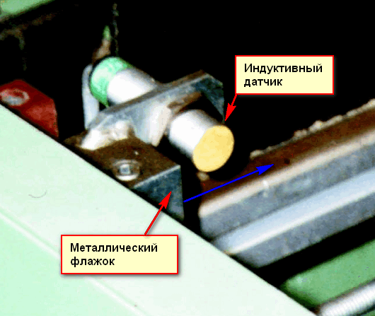
Operation of an inductive sensor. The flag moves to the right, and when it reaches the sensor sensitivity zone, the sensor is triggered.
By the way, sensor manufacturers warn that it is not recommended to connect an incandescent bulb directly to the sensor output. I already wrote about the reasons -.
Characteristics of inductive sensors
How are the sensors different?
Almost everything that is said below applies not only to inductive, but also to optical and capacitive sensors.
Construction, body type
There are two main options here - cylindrical and rectangular. Other cases are used extremely rarely. Housing material - metal (various alloys) or plastic.
Cylindrical probe diameter
Basic dimensions - 12 and 18 mm. Other diameters (4, 8, 22, 30 mm) are rarely used.
To fix the 18 mm sensor, you need 2 keys for 22 or 24 mm.
Switching distance (working clearance)
This is the distance to the metal plate at which reliable sensor operation is guaranteed. For miniature sensors, this distance is from 0 to 2 mm, for sensors with a diameter of 12 and 18 mm - up to 4 and 8 mm, for large sensors - up to 20 ... 30 mm.
Number of wires to connect
Let's get to the schematics.
2-wire. The sensor is connected directly to the load circuit (for example, a starter coil). Just like we turn on the lights at home. Convenient for installation, but capricious to the load. They work poorly with both high and low load resistance.

2-wire sensor. Switching scheme
The load can be connected to any wire, for constant voltage it is important to observe the polarity. For sensors designed to work with alternating voltage, neither the load connection nor the polarity matters. You don't have to think about how to connect them at all. The main thing is to provide current.
3-wire. The most common. There are two wires for power and one for load. I will tell you more separately.
4- and 5-wire. This is possible if two outputs to the load are used (for example, PNP and NPN (transistor), or switching (relay). The fifth wire is the selection of the operating mode or output status.
Types of sensor outputs by polarity
All discrete sensors can have only 3 types of outputs depending on the key (output) element:
Relay. Everything is clear here. The relay switches the required voltage or one of the power wires. This provides complete galvanic isolation from the sensor power circuit, which is the main advantage of such a circuit. That is, regardless of the sensor supply voltage, you can turn on / off the load with any voltage. Mainly used in large sensors.
Transistor PNP. This is a PNP sensor. The output is a PNP transistor, that is, the “positive” wire is switched. To the “minus” the load is connected permanently.
Transistor NPN.The output is an NPN transistor, that is, the “negative”, or neutral wire is switched. The "plus" load is connected permanently.
You can clearly understand the difference by understanding the principle of operation and the switching circuits of transistors. This rule will help: Where the emitter is connected, that wire is switched. The other wire is connected to the load permanently.
Below will be given sensor wiring diagrams, which will clearly show these differences.
Types of sensors by output status (NC and NO)
Whatever the sensor, one of its main parameters is the electrical state of the output at the moment when the sensor is not activated (it is not affected in any way).
The output at this moment can be turned on (power is supplied to the load) or turned off. Accordingly, they say - normally closed (normally closed, NC) contact or normally open (NO) contact. In foreign equipment, respectively - NC and NO.
That is, the main thing you need to know about the transistor outputs of the sensors is that there can be 4 varieties of them, depending on the polarity of the output transistor and on the initial state of the output:
- PNP NO
- PNP NC
- NPN NO
- NPN NC
Positive and negative operation logic
This concept refers rather to actuators that are connected to sensors (controllers, relays).
NEGATIVE or POSITIVE logic refers to the voltage level that activates the input.
NEGATIVE logic: the controller input is activated (logic “1”) when connected to GND. The S/S terminal of the controller (common wire for digital inputs) must be connected to +24 VDC. Negative logic is used for NPN sensors.
POSITIVE logic: the input is activated when connected to +24 VDC. The S/S terminal of the controller must be connected to GND. Use positive logic for PNP sensors. Positive logic is used most often.
There are options for various devices and connecting sensors to them, ask in the comments, we'll think together.
Continuation of the article -. In the second part, real circuits are given and the practical application of various types of sensors with a transistor output is considered.
- these are sensors that work without physical and mechanical contact. They work through an electric and magnetic field, and optical sensors are also widely used. In this article, we will analyze all three types of sensors: optical, capacitive and inductive, and at the end we will do an experiment with an inductive sensor. By the way, the people also call contactless sensors proximity switches, so don't be afraid if you see such a name ;-).
optical sensor
So, a few words about optical sensors ... The principle of operation of optical sensors is shown in the figure below
barrier
Do you remember any shots from films where the main characters had to go through optical beams and not hit any of them? If the beam was touched by any part of the body, an alarm was triggered.

The beam is emitted by some source. And there is also a “beam receiver”, that is, the thing that receives the beam. As soon as there is no beam on the beam receiver, the contact will immediately turn on or off in it, which will directly control the alarm or something else at your discretion. Basically, a beam source and a receiver, properly called a "photodetector", come in pairs.
SKB IS optical motion sensors are very popular in Russia.


These types of sensors have both a light source and a photodetector. They are located right in the body of these sensors. Each type of sensor is a complete design and is used in a number of machines where increased processing accuracy is needed, up to 1 micrometer. Basically, these are machines with a system H logical P software At board ( CNC) that work according to the program and require minimal human intervention. These non-contact sensors are built on this principle

These types of sensors are denoted by the letter “T” and are called barrier. As soon as the optical beam was interrupted, the sensor worked.
Pros:
- range can reach up to 150 meters
- high reliability and noise immunity
Minuses:
- at large sensing distances, fine adjustment of the photodetector to the optical beam is required.
Reflex
The reflective type of sensors is indicated by the letter R. In these types of sensors, the emitter and receiver are located in the same housing.

The principle of operation can be seen in the figure below.

Light from the emitter is reflected from some reflector (reflector) and enters the receiver. As soon as the beam is interrupted by any object, the sensor is triggered. This sensor is very convenient on conveyor lines when counting products.
diffusion
And the last type of optical sensors - diffusion - denoted by the letter D. They may look different:


The principle of operation is the same as that of the reflex, but here the light is already reflected from objects. Such sensors are designed for a small sensing distance and are unpretentious in their work.

Capacitive and inductive sensors
Optics are optics, but inductive and capacitive sensors are considered the most unpretentious in their work and very reliable. This is how they look like

They are very similar to each other. The principle of their operation is associated with a change in the magnetic and electric fields. Inductive sensors are triggered when any metal is brought to them. They do not “peck” on other materials. Capacitive ones work on almost any substance.
How an inductive sensor works
As they say, it's better to see once than hear a hundred times, so let's do a little experiment with inductive sensor.
So, our guest is a Russian-made inductive sensor

We read what is written on it
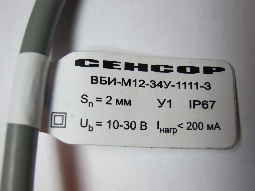
WBI sensor brand blah blah blah blah, S - sensing distance, here it is 2 mm, U1 - version for a temperate climate, IP - 67 - protection level(in short, the level of protection here is very steep), U b - voltage at which the sensor operates, here the voltage can be in the range from 10 to 30 volts, I load - load current, this sensor can deliver up to 200 milliamps of current to the load, I think this is decent.
On the reverse of the tag is a wiring diagram for this sensor.

Well, let's evaluate the work of the sensor? To do this, we cling to the load. The load we will have is an LED connected in series with a resistor with a nominal value of 1 kOhm. Why do we need a resistor? The LED at the moment of inclusion begins to frantically eat current and burns out. To prevent this, a resistor is placed in series with the LED.

On the brown wire of the sensor we supply a plus from the Power supply, and on the blue wire - a minus. The voltage I took was 15 volts.
The moment of truth is coming ... We bring a metal object to the working area of the sensor, and the sensor immediately works, as the LED built into the sensor tells us, as well as our experimental LED.

The sensor does not respond to materials other than metals. A jar of rosin means nothing to him :-).

Instead of an LED, a logic circuit input can be used, that is, the sensor, when triggered, outputs a logic one signal that can be used in digital devices.
Conclusion
In the world of electronics, these three types of sensors are in increasing use. Every year the production of these sensors is growing and growing. They are used in absolutely different areas of industry. Automation and robotics would not be possible without these sensors. In this article, I have analyzed only the simplest sensors that give us only an “on-off” signal or, to put it in a professional language, one bit of information. More sophisticated types of sensors can provide different parameters and can even connect directly to computers and other devices.
Buy inductive sensor
In our radio store, inductive sensors cost 5 times more than if they were ordered from China from Aliexpress.

Here You can look at a variety of inductive sensors.