Electronic homemade circuits. Amateur radio circuits and homemade designs. Circuit Assembly Methods
You can make the simplest electronic circuits for everyday use with your own hands, even without deep knowledge in electronics. In fact, at the household level, radio is very simple. Knowledge of the elementary laws of electrical engineering (Ohm, Kirchhoff), general principles of operation of semiconductor devices, skills in reading circuits, the ability to work with an electric soldering iron is enough to assemble a simple circuit.
Ham radio workshop
No matter how complex the scheme would have to be, you must have a minimum set of materials and tools in your home workshop:
- Side cutters;
- Tweezers;
- Solder;
- Flux;
- Circuit boards;
- Tester or multimeter;
- Materials and tools for the manufacture of the body of the device.
You should not purchase expensive professional tools and devices to begin with. An expensive soldering station or digital oscilloscope is of little help to a beginner radio amateur. At the beginning of the creative path, the simplest instruments are quite enough, on which you need to hone your experience and skills.

Where to start
Do-it-yourself radio circuits for the home should not exceed the level of complexity that you own, otherwise it will only mean wasted time and materials. With a lack of experience, it is better to limit yourself to the simplest schemes, and as you accumulate skills, improve them, replacing them with more complex ones.
Usually, most of the literature from the field of electronics for beginner radio amateurs gives a classic example of making simple receivers. This is especially true of classical old literature, in which there are not so many fundamental errors in comparison with contemporary literature.
Note! These schemes were designed for the huge power of transmitting radio stations in the past. Today, transmitting centers use less power to transmit and try to get into the shorter wavelength range. Do not waste time trying to make a working radio using the simplest circuit.
Radio circuits for beginners should include a maximum of a couple of active elements - transistors. So it will be easier to understand the operation of the circuit and increase the level of knowledge.
What can be done
What can be done so that it is not difficult and can be used in practice at home? There can be many options:
- apartment call;
- Christmas tree garlands switch;
- Backlight for modding the computer system unit.

Important! Appliances to be powered by household AC power should not be designed unless there is sufficient experience. It is dangerous for life and for others.
Pretty simple circuits have amplifiers for computer speakers, made on specialized integrated circuits. Devices assembled on their basis contain a minimum number of elements and practically do not require adjustment.
You can often find circuits that need elementary alterations, improvements that make it easier to manufacture and configure. But this should be done by an experienced master in order to make the final version more accessible to a beginner.
On what to build
Most of the literature recommends designing simple circuits on circuit boards. At present, this is quite easy. There is a wide variety of circuit boards with different hole patterns and printed tracks.
The principle of installation is that the parts are installed on the board in free places, and then the necessary conclusions are connected to each other by jumpers, as indicated in the circuit diagram.

With due care, such a board can serve as the basis for many circuits. The power of the soldering iron for soldering should not exceed 25 W, then the risk of overheating the radio elements and printed conductors will be minimized.
The solder should be fusible, such as POS-60, and it is best to use pure pine rosin or its solution in ethyl alcohol as a flux.
Highly qualified radio amateurs can design a printed circuit board pattern themselves and execute it on foil material, on which radio elements are then soldered. The design developed in this way will have optimal dimensions.
Design of the finished structure
Looking at the creations of beginners and experienced craftsmen, one can come to the conclusion that the assembly and adjustment of the device is not always the most difficult part of the design process. Sometimes a properly working device remains a set of parts with soldered wires, not closed by any case. At present, you can no longer be puzzled by the manufacture of the case, because on sale you can find all kinds of sets of cases of any configuration and dimensions.

Before you start manufacturing the design you like, you should fully think through all the stages of the work: from the availability of tools and all radio elements to the version of the case. It will be completely uninteresting if in the process of work it turns out that one of the resistors is missing, and there are no replacement options. The work is best done under the guidance of an experienced radio amateur, and, in extreme cases, periodically monitor the manufacturing process at each stage.
Video
Below are simple light and sound circuits, mainly assembled on the basis of multivibrators, for beginner radio amateurs. In all circuits, the simplest element base is used, complex adjustment is not required, and elements can be replaced with similar ones within a wide range.
Electronic duck
A toy duck can be equipped with a simple two-transistor "quack" simulator circuit. The circuit is a classic two-transistor multivibrator with an acoustic capsule in one arm, and two LEDs that can be inserted into the eyes of the toy serve as the load of the other. Both of these loads work alternately - either a sound is heard, or LEDs flash - the eyes of a duck. A reed switch can be used as a power switch SA1 (can be taken from the SMK-1, SMK-3, etc. sensors used in security alarm systems as door opening sensors). When a magnet is brought to the reed switch, its contacts are closed and the circuit starts to work. This can happen when the toy is tilted to a hidden magnet or a kind of “magic wand” with a magnet is brought up.
Transistors in the circuit can be any p-n-p type, low or medium power, for example MP39 - MP42 (old type), KT 209, KT502, KT814, with a gain of more than 50. You can also use transistors of the n-p-n structure, for example KT315, KT 342, KT503 , but then you need to change the polarity of the power supply, turn on the LEDs and the polar capacitor C1. As an acoustic emitter BF1, you can use a capsule type TM-2 or a small-sized speaker. Establishing the circuit is reduced to the selection of the resistor R1 to obtain a characteristic quacking sound.
The sound of a bouncing metal ball
The circuit quite accurately imitates such a sound, as the capacitor C1 discharges, the volume of the “beats” decreases, and the pauses between them decrease. At the end, a characteristic metallic rattle will be heard, after which the sound will stop.

Transistors can be replaced with similar ones, as in the previous circuit.
The total duration of the sound depends on the capacitance C1, and C2 determines the duration of the pauses between the “beats”. Sometimes, for a more believable sound, it is useful to choose a transistor VT1, since the operation of the simulator depends on its initial collector current and gain (h21e).
Engine Sound Simulator
They can, for example, sound a radio-controlled or other model of a mobile device.
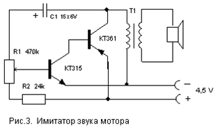
Transistor and speaker replacement options - as in the previous circuits. Transformer T1 is the output from any small-sized radio receiver (a speaker is also connected through it in the receivers).
There are many schemes for imitating the sounds of birdsong, animal voices, the whistle of a locomotive, etc. The circuit proposed below is assembled on just one digital microcircuit K176LA7 (K561 LA7, 564LA7) and allows you to simulate many different sounds depending on the resistance value connected to the X1 input contacts.

It should be noted that the microcircuit here works “without power”, that is, no voltage is applied to its positive output (leg 14). Although, in fact, the microcircuit is still powered, but this happens only when the resistance-sensor is connected to the X1 contacts. Each of the eight inputs of the microcircuit is connected to the internal power bus through diodes that protect against static electricity or incorrect connection. Through these internal diodes, the microcircuit is powered due to the presence of positive feedback on power supply through the input resistor-sensor.
The circuit consists of two multivibrators. The first one (on the elements DD1.1, DD1.2) immediately starts generating rectangular pulses with a frequency of 1 ... 3 Hz, and the second one (DD1.3, DD1.4) starts working when the logic level " 1". It generates tone pulses with a frequency of 200 ... 2000 Hz. From the output of the second multivibrator, pulses are fed to a power amplifier (transistor VT1) and a modulated sound is heard from the dynamic head.
If you now connect a variable resistor with a resistance of up to 100 kOhm to the input jacks X1, then there is a feedback on the power supply and this transforms the monotonous intermittent sound. By moving the slider of this resistor and changing the resistance, you can achieve a sound reminiscent of the trill of a nightingale, the chirping of a sparrow, the quacking of a duck, the croaking of a frog, etc.
Details
The transistor can be replaced with KT3107L, KT361G, but in this case, you need to put R4 with a resistance of 3.3 kOhm, otherwise the sound volume will decrease. Capacitors and resistors - of any type with ratings close to those indicated on the diagram. It must be borne in mind that the above-mentioned protective diodes are absent in the K176 series microcircuits of early releases and such instances will not work in this circuit! It is easy to check the presence of internal diodes - just measure the resistance between pin 14 of the microcircuit (“+” power supply) and its input terminals (or at least one of the inputs) with a tester. As with testing diodes, resistance should be low in one direction and high in the other.
The power switch in this circuit can be omitted, since in rest mode the device consumes less than 1 μA current, which is much less than even the self-discharge current of any battery!
Adjustment
A correctly assembled simulator does not require any adjustment. To change the tone of the sound, you can select a capacitor C2 from 300 to 3000 pF and resistors R2, R3 from 50 to 470 kOhm.
flasher
The flashing frequency of the lamp can be adjusted by selecting the elements R1, R2, C1. The lamp can be from a flashlight or a car 12 V. Depending on this, you need to choose the supply voltage of the circuit (from 6 to 12 V) and the power of the switching transistor VT3.

Transistors VT1, VT2 - any low-power corresponding structures (KT312, KT315, KT342, KT 503 (n-p-n) and KT361, KT645, KT502 (p-n-p), and VT3 - medium or high power (KT814, KT816, KT818).
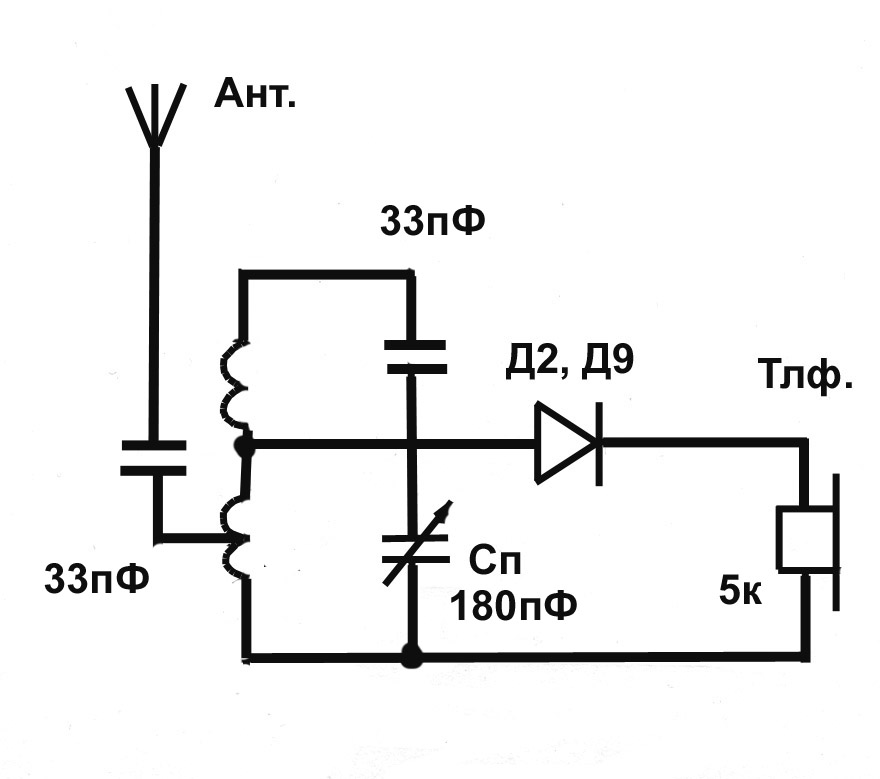
A simple device for listening to the sound of TV programs on headphones. It does not require any power and allows you to move freely within the room.

Coil L1 is a "loop" of 5 ... 6 turns of wire PEV (PEL) -0.3 ... 0.5 mm, laid along the perimeter of the room. It is connected in parallel with the TV speaker through the SA1 switch as shown in the figure. For normal operation of the device, the output power of the TV sound channel must be within 2 ... 4 W, and the loop resistance must be 4 ... 8 Ohms. The wire can be laid under the plinth or in the cable duct, while it must be placed as far as possible no closer than 50 cm from the wires of the 220 V network to reduce AC voltage interference.

Coil L2 is wound on a frame made of thick cardboard or plastic in the form of a ring with a diameter of 15 ... 18 cm, which serves as a headband. It contains 500 ... 800 turns of PEV (PEL) wire 0.1 ... 0.15 mm fixed with glue or electrical tape. A miniature volume control R and an earphone (high-resistance, for example, TON-2) are connected in series to the coil terminals.
Automatic light switch
This one differs from many schemes of similar automata by its extreme simplicity and reliability and does not need a detailed description. It allows you to turn on the lighting or some electrical appliance for a specified short time, and then automatically turns it off.

To turn on the load, it is enough to briefly press the switch SA1 without fixing. In this case, the capacitor has time to charge and opens the transistor, which controls the switching on of the relay. The turn-on time is determined by the capacitance of the capacitor C and with the nominal value indicated on the diagram (4700 mF) is about 4 minutes. An increase in the on-time is achieved by connecting additional capacitors in parallel with C.
The transistor can be any n-p-n type of medium power or even low power, such as KT315. It depends on the operating current of the relay used, which can also be any other for an actuation voltage of 6-12 V and capable of switching the load of the power you need. You can also use p-n-p type transistors, but you will need to change the polarity of the supply voltage and turn on the capacitor C. Resistor R also affects the response time to a small extent and can be 15 ... 47 kOhm, depending on the type of transistor.
List of radio elements
| Designation | Type | Denomination | Quantity | Note | Shop | My notepad | |
|---|---|---|---|---|---|---|---|
| Electronic duck | |||||||
| VT1, VT2 | bipolar transistor | KT361B | 2 | MP39-MP42, KT209, KT502, KT814 | To notepad | ||
| HL1, HL2 | Light-emitting diode | AL307B | 2 | To notepad | |||
| C1 | 100uF 10V | 1 | To notepad | ||||
| C2 | Capacitor | 0.1uF | 1 | To notepad | |||
| R1, R2 | Resistor | 100 kOhm | 2 | To notepad | |||
| R3 | Resistor | 620 ohm | 1 | To notepad | |||
| BF1 | Acoustic emitter | TM2 | 1 | To notepad | |||
| SA1 | reed switch | 1 | To notepad | ||||
| GB1 | Battery | 4.5-9V | 1 | To notepad | |||
| Bouncing metal ball sound simulator | |||||||
| bipolar transistor | KT361B | 1 | To notepad | ||||
| bipolar transistor | KT315B | 1 | To notepad | ||||
| C1 | electrolytic capacitor | 100uF 12V | 1 | To notepad | |||
| C2 | Capacitor | 0.22uF | 1 | To notepad | |||
| dynamic head | GD 0.5...1Watt 8 Ohm | 1 | To notepad | ||||
| GB1 | Battery | 9 Volt | 1 | To notepad | |||
| Engine Sound Simulator | |||||||
| bipolar transistor | KT315B | 1 | To notepad | ||||
| bipolar transistor | KT361B | 1 | To notepad | ||||
| C1 | electrolytic capacitor | 15uF 6V | 1 | To notepad | |||
| R1 | Variable resistor | 470 kOhm | 1 | To notepad | |||
| R2 | Resistor | 24 kOhm | 1 | To notepad | |||
| T1 | Transformer | 1 | From any small radio receiver | To notepad | |||
| Universal sound simulator | |||||||
| DD1 | Chip | K176LA7 | 1 | K561LA7, 564LA7 | To notepad | ||
| bipolar transistor | KT3107K | 1 | KT3107L, KT361G | To notepad | |||
| C1 | Capacitor | 1 uF | 1 | To notepad | |||
| C2 | Capacitor | 1000 pF | 1 | To notepad | |||
| R1-R3 | Resistor | 330 kOhm | 1 | To notepad | |||
| R4 | Resistor | 10 kOhm | 1 | To notepad | |||
| dynamic head | GD 0.1...0.5Watt 8 Ohm | 1 | To notepad | ||||
| GB1 | Battery | 4.5-9V | 1 | To notepad | |||
| flasher | |||||||
| VT1, VT2 | bipolar transistor | ||||||
Beginner radio amateurs who are interested in independently assembling circuits and repairing various electronic devices are lost in a sea of numerous terms and details. Meanwhile, you can give a number of tips on what knowledge is needed in the first place, what devices to use, how to navigate when choosing circuit elements.
Required knowledge
For radio amateurs it is very important:
- know and understand the basic laws of electrical engineering;
- be able to navigate the schemes;
- clearly define the role of each element in the diagram and represent visually how it looks.
Important! Theoretical knowledge must be constantly reinforced by practice.
Tools and devices
To assemble amateur radio circuits and home-made structures, you must have the following tools:
- Soldering iron, the power of which must be chosen average - no more than 40 watts. More advanced craftsmen are thinking about purchasing a soldering station;
- Side cutters. Not too massive tool for working with radio devices;

- Tin-lead solder exists in the form of a wire.
Important! Among all devices, the main, and often the only one, is a digital multimeter or analog tester, through which you can measure all the main parameters of the circuit.
Before you start assembling simple and interesting do-it-yourself radio circuits, you can practice dismantling old radio equipment. At the same time, a practical skill is formed in soldering work.
- In ancient televisions with lamps, a quite suitable thing is a supply transformer. It can be used in many DIY radios. For example, to assemble a charger for a car battery or a power supply unit for a sound amplifier. The main thing is to know its technical data;
- In obsolete radio electronic devices: television equipment, video recorders, conventional tape recorders, there are whole microcircuits ready for use. An example would be an audio amplifier whose circuit is constructed by simply assembling components, without etching on printed circuit boards, etc.;
- The tone control is also used in finished form. At the same time, the assembled sound amplifier will receive new options: the ability to control the low-frequency and high-frequency ranges, change the balance in stereo speakers;
- Basically, all devices manufactured by radio amateurs operate on five-, nine- and twelve-volt power supplies. Such power supplies from old equipment will be the most useful.
As cases for circuits, you can use any improvised designs or buy ready-made ones, of different sizes and shapes. Shrouds from non-working devices are often used for new radio homemade products.
A non-working PSU from a computer is very valuable, where it comes from:
- many radio components: transistors, capacitors, diodes, resistances that are useful for assembled devices;
- cooling radiators are an important accessory for high power transistors;
- good wires;
- the hull itself is a great place to place new structures.

Circuit Assembly Methods
- Hanging installation. Simple soldering of components in accordance with the developed scheme. Soldered nodes can be installed on supporting platforms. The method is suitable for constructing radio circuits from a small number of parts;
- Mounting on a printed circuit board - a textolite platform on which foil tracks are made as connecting conductors.
The second method is divided into several options:
- Mechanical. Cutting tracks with a sharp object to exclude contact connections in unnecessary places;
- Chemical. With the help of varnish or paint on the foil, you need to draw the required scheme. Then immerse in a special composition - a solution of ferric chloride. After processing, a wiring corresponding to the drawing will be obtained, and all areas without varnish will be removed by dissolution;
- Laser ironing.
What schemes to start with
The classic start for radio amateurs is to make a simple detector receiver. The circuit contains a small number of components, and its assembly will be within the power of everyone. Then you can supplement the device with an audio amplifier using transistors. With the advent of experience and understanding, work with microcircuits begins.
A large number of interesting and very simple radio homemade options with a description of the details, the provision of diagrams are on the RadioKot website. You can, for example, assemble color music, pulsed clock illumination, a stereo transmitter, and much more. There are also useful forums where you can clarify complex issues, chat with experienced craftsmen.
As skills are acquired, interest in assembling complex devices will increase. Radio-electronic homemade products are one of the most exciting activities for people of all ages.
Video
Schemes of homemade measuring instruments
The circuit of the device, developed on the basis of a classic multivibrator, but instead of load resistors, transistors with the opposite main conductivity are included in the collector circuits of the multivibrator.
It's good if your lab has an oscilloscope. Well, if it is not there and it is not possible to buy it for one reason or another, do not worry. In most cases, it can be successfully replaced by a logic probe, which allows you to control the logical levels of signals at the inputs and outputs of digital integrated circuits, determine the presence of pulses in the controlled circuit and reflect the information received in visual (light-color or digital) or audio (tonal signals of various frequencies). ) forms. When setting up and repairing structures based on digital integrated circuits, it is far from always so necessary to know the characteristics of the pulses or the exact values of the voltage levels. Therefore, logic probes make it easy to set up, even if you have an oscilloscope.
A huge selection of different pulse generator circuits is presented. Some of them form a single pulse at the output, the duration of which does not depend on the duration of the triggering (input) pulse. Such generators are used for a wide variety of purposes: simulating the input signals of digital devices, when checking the performance of digital integrated circuits, the need to supply a certain number of pulses to a device with visual control of processes, etc. Others generate sawtooth and rectangular pulses of various frequencies, duty cycles and amplitude
The repair of various components and devices of low-frequency radio-electronic equipment and technology can be greatly simplified if you use a function generator as an assistant, which makes it possible to investigate the amplitude-frequency characteristics of any low-frequency device, transients and nonlinear characteristics of any analog devices, and also has the ability to generate rectangular pulses. form and simplify the process of setting up digital circuits.
When setting up digital devices, one more device is definitely needed - a pulse generator. An industrial generator is a rather expensive device and is rarely on sale, but its analogue, although not so accurate and stable, can be assembled from available radio elements at home
However, the creation of a sound generator that produces a sinusoidal signal is not an easy and rather painstaking task, especially in terms of adjustment. The fact is that any generator contains at least two elements: an amplifier and a frequency-dependent circuit that determines the frequency of oscillations. Usually it is connected between the output and input of the amplifier, creating a positive feedback (POS). In the case of an RF generator, everything is simple - a single-transistor amplifier and an oscillatory circuit that determines the frequency are enough. For the audio frequency range, it is difficult to wind the coil, and its quality factor turns out to be low. Therefore, in the audio frequency range, RC elements are used - resistors and capacitors. They filter the fundamental harmonic of the oscillations rather poorly, and therefore the sinusoidal signal turns out to be distorted, for example, limited in peaks. To eliminate distortion, amplitude stabilization circuits are used to maintain a low level of the generated signal when distortion is still invisible. It is the creation of a good stabilizing circuit that does not distort the sinusoidal signal that causes the main difficulties.
Often, having assembled the structure, the radio amateur sees that the device is not working. After all, a person does not have sense organs that allow him to see an electric current, an electromagnetic field, or processes occurring in electronic circuits. Radio measuring instruments help to do this - the eyes and ears of a radio amateur.
Therefore, some means of testing and checking telephones and loudspeakers, audio frequency amplifiers, various sound recording and sound reproducing devices are needed. Such a tool is amateur radio circuits for audio frequency signal generators, or, more simply, a sound generator. Traditionally, it produces a continuous sinusoidal signal, the frequency and amplitude of which can be changed. This allows you to check all ULF stages, find faults, determine the gain, take amplitude-frequency characteristics (AFC) and much more.
A simple amateur radio home-made prefix is considered that turns your multimeter into a universal device for checking zener diodes and dinistors. PCB drawings available
So. Life has turned out so that I have a house in the village with gas heating. You can't live there permanently. The house is used as a summer cottage. A couple of winters stupidly left the boiler on with a minimum coolant temperature.
But there are two downsides.
1. Gas bills are astronomical.
2. If there is a need to come to the house in the middle of winter, the temperature in the house is around 12 degrees.
Therefore, something had to be invented.
I'll clarify right away. The presence of a WI-FI access point in the relay coverage area is mandatory. But, I think, if you get confused, you can put a connected mobile phone next to the sensor and give out a signal from the phone.
Do-it-yourself motion sensor connection 4 pins diagram
Do-it-yourself motion sensor connection diagram

It happens that you need to install lighting in the country, or in the house, which will be triggered when moving or a person or someone else.
The motion sensor, which was ordered by me from Aliexpress, works well with this function. The link to which will be below. By connecting light through the motion sensor, when a person passes through his field of vision, the light turns on, burns for 1 minute. and turns off again.
In this article I tell you how to connect such a sensor if it does not have 3 contacts, but 4 like this one.
Do-it-yourself power supply from an energy-saving light bulb
 When to get 12 volts for LED strip, or for some other purpose, there is an option to make such a power supply with your own hands.
DIY fan speed controller

This regulator allows smooth adjustment variable resistor fan speed.
The floor fan speed controller circuit came out the simplest. To fit into the case from an old Nokia phone charger. There also climbed the terminals from a conventional electrical outlet.
The installation is quite tight, but this was due to the size of the case.
DIY lighting for plants
DIY lighting for plants

There is a problem with the lack of lighting. plants, flowers or seedlings, and there is a need for artificial light for them, and this is the light we can provide DIY LEDs.
DIY brightness control
DIY brightness control

It all started with the fact that after I installed halogen lamps at home for lighting. When turned on, they often burned out. Sometimes even 1 bulb a day. Therefore, I decided to make a smooth turn-on of lighting based on a dimmer with my own hands, and I am attaching a dimmer circuit.
Do-it-yourself refrigerator thermostat
Do-it-yourself refrigerator thermostat

It all started with the fact that after returning from work and opening the refrigerator found it warm. Turning the thermostat knob did not help - the cold did not appear. Therefore, I decided not to buy a new unit, which is also rare, but to make an electronic thermostat on the ATtiny85 myself. With the original thermostat, the difference is that the temperature sensor is on the shelf, and not hidden in the wall. In addition, 2 LEDs appeared - they signal that the unit is on or the temperature is above the upper threshold.
DIY soil moisture sensor
DIY soil moisture sensor

This device can be used for automatic watering in greenhouses, flower greenhouses, flower beds and indoor plants. Below is a diagram by which you can make the simplest sensor (detector) of soil moisture (or dryness) with your own hands. When the soil dries out, voltage is applied, with a current of up to 90mA, which is quite enough, turn on the relay.
It is also suitable for automatically turning on drip irrigation to avoid excess moisture.
Fluorescent lamp power circuit
Power supply circuit for a fluorescent lamp.

Often, when energy-saving lamps fail, the power circuit burns out in it, and not the lamp itself. As is known, LDS with burned-out filaments, it is necessary to feed the mains with rectified current using a starterless starting device. In this case, the filaments of the lamp are shunted with a jumper and to which a high voltage is applied to turn on the lamp. There is an instantaneous cold ignition of the lamp, a sharp increase in voltage on it, when starting without preheating the electrodes. In this article, we will look at do-it-yourself LDS lamp start.
USB keyboard for tablet
USB keyboard for tablet

Somehow, suddenly, he took something and decided to buy a new keyboard for his PC. The desire for novelty is unstoppable. Changed the background color from white to black, and the color of the letters from red - black to white. A week later, the desire for novelty naturally went away like water in the sand (an old friend is better than two new ones) and the new thing was sent to the closet for storage - until better times. And now they came for her, did not even imagine that it would happen so quickly. And therefore the name would be even better suited not which is, but how to connect usb keyboard to tablet