Making wiring harnesses how to do. Development of the technological process for the manufacture of bundles. Modern technologies for designing CS and bundles
A set of designed wires and cables connected to one another in some way and, if necessary, equipped with electrical installation elements (lugs, connectors, etc.) is called tourniquet. According to their purpose, the harnesses are divided into intra-block and inter-block.
Intrablock harnesses serve for the electrical connection of individual units, blocks and electrical parts inside the device, and interblock are used for electrical connection of various electronic equipment and devices into one system.
The design of the intra-unit harness installation is determined by the type of the device case, the requirements for their maintenance and repair. Depending on the placement of nodes in the body, such bundles can be: flat fixed with detachable connections; flat movable with one-piece connections; volumetric mobile; volumetric with movable outlets. Permanent connections for in-block installation are used mainly in electronic equipment designed for harsh operating conditions.
A typical technological process for manufacturing a bundle consists of cutting wires and insulating tubes, laying wires on a template, tying them into a bundle, developing the ends of the bundle wires and marking them, controlling the manufactured bundle (continuity), protecting the bundle insulating tape and its final control (visual inspection for compliance with the standard and continuity).
Harness layout template it is a rectangular plate made of plastic or plywood, on the surface of which a full-size harness diagram is applied and end and corner pins are fixed (Fig. 4.8).
Laying the wire begins by fixing it on the corner stud. Then the wire is laid according to the bundle scheme, bending it on the corner studs and fixing it on the end stud. The start and end pins have the same number. When all the wires are on the template, they are tied with linen thread.
In bundles where it is impossible to replace damaged wires, spare wires are provided, the number of which is 8-10% of the total number of wires in the bundle, but not less than two. The length and section of the spare wires must be equal to the largest length and section of the wires present in the bundle. The length of the harness taps must be sufficient to connect to the nodes and elements of the device circuit without tension; in addition, you should have some margin of length (10-12 mm) for re-stripping and soldering each end of the wire.
When making harnesses, the following requirements must be met:
two or more parallel insulated wires running in the same direction and with a length of more than 80 mm must be bundled;
longer wires should be laid at the top of the bundle so that the branch of the bundle comes out from under them. Wires of small sections (0.2 mm 2) should be laid in the central part of the bundle;
depending on the operating conditions, as well as on the insulation of the wires included in the bundle, it is necessary to knit with threads, braid or tapes made of synthetic materials or winding with electrical insulating tapes or films. It is also possible to use electrically insulating tubes instead of winding with a tape or to perform mechanical and automatic knitting of bundles with threads with a tension that does not violate the insulation of the wires;
the knitting step of the harness loops depends on the diameter of the harness and is selected from Table 4.3.

in places where the tourniquet is exposed (before and after it), bandages from 2-3 loops placed nearby should be made. At the beginning and end of knitting, there should also be bandages, which consist of two to five loops and have end knots. A loop must be made in front of each wire coming out of the bundle. An example of knitting and laying with a bandage is shown in Fig. 4.9;
depending on the number of wires and the diameter of the bundles, knitting must be done in one, two or more threads. Before knitting, it is recommended to grate or soak the threads with ceresin. Knots of linen threads after knitting must be covered with glue (for example, BF-4) or varnish; the ends of kapron threads after knitting must be melted.
After knitting the wires into a bundle, their ends are checked. In this case, all ends of the wires are marked in accordance with the wiring diagram.

wire marking, cable products and harnesses during electrical installation, it should provide the ability to check electrical circuits, find faults and repair equipment. For marking, the following methods are used: laying in a bundle of wires that have different colors; coloring or numbering of polyvinyl chloride tubes used to clamp the ends of the insulation (the tubes are marked on the machine or the numbers are written by hand with marking ink);
putting plastic tags on the wires with symbols of the connection points;
making a mark on the insulation using colored printing foil (for wires with PVC and polyethylene insulation and cables of the PK type);
use of a metal tag (mainly for cables of the RK type);
use of adhesive marking tape (with a bandage of 1.5 ... 3 turns per wire or cable).
The marking is applied to both ends of the wire, cable or bundle at the points of their connection. The designation of wires, cables and bundles on marking tags, tapes and tubes or directly on the wires must correspond to the mark shown in the technical documentation. If the tag put on the wire or cable is not glued, it is tied on the wire (cable) with a knot or loop.
To mark wires with an insulation diameter of up to 1 mm, use colored marking tubes with an inner diameter corresponding to the wire diameter.
The marking of wires in the bundle is done using tags or tapes from polymer materials. The length of the tags or the width of the tapes must be no more than 12 mm.
Then the harness is controlled by dialing, for which they are connected by a device (indicator) in series to the ends of the wires of the harness with the same numbers.
The control of complex harnesses is carried out on special semi-automatic stands according to a given program. All information about such control is recorded in the computer.
Harnesses, wires and cables are fixed to the REA housing or its elements using: brackets, tapes, clamps, adhesives, mastics, compounds, threads, ribbons, plastic self-adhesive tapes.
Staples, tapes and clamps must correspond to the shape of the tourniquet and, when fastened, prevent its displacement.
In order not to damage the insulation of the wires when fastened with metal brackets and clamps, it is necessary to place elastic gaskets made of insulating material under them, protruding beyond the edge of the brackets (clamps) by at least 1 mm.
The distance between brackets or clamps when attaching them to linear sections must be selected depending on the diameter of the bundle (wire or cable) in the range from 100 to 300 mm. Identical wires with a cross section of less than 0.35 mm 2 must be fastened with a distance between the fastening points of not more than 80 mm.
When glue or mastic is used to fix wires, bundles and cables, the distance between the gluing points should be selected depending on the diameter of the wire (bundle or cable) according to Table 4.4

Bundles with a diameter of more than 15 mm, when glued, are fixed with threads through a hole in the chassis.
The passage of a bundle, wire or cable through a hole in a metal chassis must be done through an insulating sleeve that is installed in the hole.
When passing wires, harnesses and cables from the fixed part of the device to the moving part (for example, from the case to the board or panel, etc.), it is recommended to place them in such a way that the wires are twisted and not bent when the moving part is removed. At the same time, the moving parts of the tourniquet do not need to be tied and leave the necessary margin in length.
Soldering and tinning: purpose, application and physical and chemical bases. Solder, fluxes, their brands and applications. Soldering technology with soft and hard solders, temperature conditions, heat sink. Group methods of soldering. Equipment and tools: purpose, design and methods of work. Methods for soldering wires of various grades and sections. Ultrasonic soldering. Laser soldering. Requirements for soldering connections, quality control. Appointment and application of tinning, quality control. Automation of soldering and tinning processes
Soldering- physico-chemical process of obtaining a joint as a result of the interaction of solid and liquid metal (solder). The layers resulting from this interaction at the boundaries of the seam and the surfaces of the parts to be joined are called junctions. To obtain junctions, it is necessary to remove oxide films from the joined surfaces and create conditions for the interaction of solid and liquid metals. During the crystallization of the more fusible solder that has interacted with the material of the brazed parts, a brazed joint is obtained.
One of the advantages of soldering is the ability to connect many elements that make up the product into a single whole in one go. Soldering, like no other connection method, meets the conditions of mass production. It allows you to connect dissimilar metals, as well as metals with. glass, ceramics, graphite and other non-metallic materials.
Tinning is the process of soldering electrical installation elements (ERE terminals, printed circuit board contact pads, metallized holes, cores of mounting wires and cables, etc.). It is necessary to improve the solderability of the connected surfaces of elements during their installation.
To make a good solder joint you need:
7. prepare the surfaces of the soldered parts;
8. activate soldered metals and solder;
9. provide interaction at the boundary "base metal - liquid solder;
10. create conditions for the crystallization of the liquid metal layer of the solder.
Surface preparation involves removing contaminants and oxide films from it that interfere with wetting - its molten solder. Films are removed by mechanical or chemical means. For mechanical cleaning
a thin surface layer of metal is removed using sandpaper, a wire brush, etc. synthetic material containing abrasive particles. Surface roughness after mechanical cleaning contributes to the spreading of flux and solder, since small scratches on the surface are the smallest capillaries.
Chemical treatment (degreasing) of the surface of the product is carried out in solutions of alkalis or organic solvents (acetone, gasoline, alcohol, carbon tetrachloride, freon, alcohol-gasoline and alcohol-freon mixtures) by wiping, lowering into a bath, etc.
Cleaned parts must be immediately sent for tinning and soldering, since the shelf life for copper is 3-5 days, for silver - 10-15 days.
Activation of the joined metals and solder occurs with the help of various fluxes, the creation of a special gaseous medium or physical and mechanical effects (mechanical vibrations, ultrasonic vibrations, etc.). Activation is necessary, since when metals are heated and solder melts, their surface layers interact with atmospheric oxygen, which leads to the formation of a new oxide film.
Soldering with flux is the most common. The molten flux spreads over the soldered surface and the solder, wets them and interacts with them, as a result of which the oxide film is removed. But the use of fluxes can lead to the fact that their residues after soldering, as well as the products of their interaction with oxide films, create slag inclusions in the brazed joint. This reduces the strength of the joint and leads to its corrosion. To avoid this, flux residues after soldering are washed off (wiped) usually with organic solvents.
In order to ensure interaction at the "base metal - liquid solder" interface, it is necessary to achieve good wetting of the base metal surface (ERE leads, petals, wires, etc.) with molten solder. Strength, corrosion resistance and other properties of solder joints. The process of wetting and spreading of solder is influenced by certain technological factors (the method of removing the oxide film, the brand of flux used, the soldering mode, etc.).
Crystallization of the liquid metal layer is carried out after the removal of the source of thermal energy. The crystallization process has a significant impact on the quality of solder joints.
Solder and fluxes for soldering designed to perform technological processes of hot tinning and soldering of non-ferrous and ferrous metals and metallic and non-metallic materials metallized by them. They are divided into:
solders for low-temperature soldering with a melting point of less than 450 °C;
solder for high temperature folder with melting point above 450°C.
The symbol for solder grades consists of the letters "P" or "Pr" and the following abbreviated names of the main components: tin - O, lead - C, antimony - Su, bismuth - Vi * cadmium or cobalt - K, silver - Cp, copper - M , indium - Yin, zinc - C, nickel - N, gallium - Gl, germanium - G, titanium - T, gold - Zl, manganese - Mts, boron - B, phosphate - F, brass or lithium - L, iron - F , aluminum - A. Further, the content of the main component is indicated as a percentage of the mass. The letter "P", which stands at the end of the brand with a hyphen, means that the solder has an increased purity.
The main brands of solders and their melting temperature (T pl) are shown in Table 4.5.

Fluxes are intended for use in technological processes of soldering and hot tinning in order to remove the oxide film from soldered surfaces and solder, protect the surface of metals and solder from oxidation during soldering, as well as reduce the surface tension of molten solder at the metal-solder-flux interface
The symbol for flux grades consists of the letter "F" (flux) and the abbreviated name of its constituent components: K - rosin, Sp - alcohol, T - triethanolamine, Et - ethyl acetate, C - salicylic acid, B - benzoic acid, Bf - cadmium (or zinc) boron fluoride, P - polyester resin, D - diethyl amine, CK - semicarbozide, Gl - glycerin, Fs - orthophosphoric acid, C - zinc chloride, A - ammonium chloride, B - water, L - laprol, Kp - catapine, M - maleic acid.
Fluxes can be low-temperature (use temperature less than 450 °C) and high-temperature (with use temperature over 450 °C). Depending on the corrosive effect on the metal to be brazed, they are divided into the following groups: non-corrosive inactive, non-corrosive weakly active, slightly corrosive active, corrosive active, corrosive highly active.
To avoid field joint corrosion, residues of corrosive and even mildly corrosive fluxes must be removed immediately after soldering. Remove fluxes with liquids in which they dissolve. For some brands of fluxes, these may be organic solvents, for others, water.
The most common brands of fluxes are given in Table 4.6.


In addition to fluxes, protective liquids are used to protect the mirror of molten low-temperature solder from oxidation in tinning and soldering baths (for example, ZhZ-1, ZhZ-2, TP-22). They are a mixture of petroleum oils with organic components.
The quality of solders and soldering fluxes is determined by technological characteristics: spreading coefficient (K p) and wetting time (t CM). Coefficient K p \u003d Sp /Sq, where S p is the area occupied by solder; Sq - area of unmelted solder in the initial state; tCM - the time during which the mounting element is tinned (should be no more than 3 s).
Soldering technology with soft and hard solders, temperature conditions, heat sink. The technological process of soldering consists of the following operations:
preparation of surfaces of connected elements for soldering; fixing the connected elements tightly to one another; applying a dosed amount of flux and solder; heating parts to a predetermined temperature and holding for a certain time; *
cooling of the soldered joint without shifting the parts included in it;
clearing the connection; soldering quality control.
Soft (low-temperature) solders (see Table 4.5) are used for electrical installation of equipment. Therefore, the temperature regimes for their use depend on the permissible temperature for those elements that take part in the installation. Soldering can be done with a soldering iron or in molten solder baths. When tinning and soldering with molten solder, the required bath temperature increases for each grade of solder according to the formula
tp = tnk + (45...80) °С,
where t n - solder temperature, tHK - crystallization start temperature (first digit T pl in table 4.5). Exceeding value (45...80) °С above tHK depends on the mass of the product to be soldered, the immersion time, the flux used, the restrictions on thermal effects in accordance with the technical specifications for the ERE.
To avoid overheating of soldered EREs, a heat sink is used, which is fixed to the ERE terminals during soldering.
There are other methods of heat removal during individual and group soldering of circuit boards. Mounting plate 2 (fig.4.10, a) is installed in fixture 5, made by injection molding in the form of a thermal block. The case is built-in racks 3 pressed by springs 6, bearing support copper sockets 4 from above, having slots for leads. Mounting plate 2 is installed on these heat sinks so that the leads of the radioelements fit into the slots of the sockets. The board is fixed in the device by turning the clamping bar 1. Thus, during the period of individual soldering, heat removal is carried out by the entire body of the device.
When group soldering hinged elements on the circuit board, the method of heat removal is used, carried out with the help of shot from aluminum wire with a diameter of 3 mm (Fig. 4.10, b). The shot 3 is loaded into the holder 1, where the circuit board 2 is inserted before group soldering by immersion or hydrostatic method. At the end of soldering, the shot spills out.
Hard (high-temperature) solders are used for structural soldering of mechanical joints in the manufacture of large-sized parts (for example, chassis, cases, etc.). High-temperature soldering of mechanical joints is performed in high frequency current fields (HF), in furnaces or baths with molten salt.

Induction soldering (TVCh). A technological device for induction soldering or soldering with high frequency currents (HFC) is an inductor, which is a coil made of a highly conductive tubular material through which a coolant is pumped. An HDTV generator serves as equipment for soldering. Typically, induction brazing is used to join elements operating at microwave frequencies, such as microwave waveguides. The quality of the connection is improved when the soldering process is carried out in a vacuum or in a protective gas environment (hydrogen, nitrogen, or mixtures thereof). A big disadvantage of HDTV soldering is the need for special devices for each assembly unit.
Soldering in ovens with a controlled atmosphere ensures uniformity of heating. The soldered materials are heated in an active gaseous medium. In this case, fluxing can be omitted.
Soldering in bathtubs with molten salt is used to assemble large-sized products. The composition of the melt is selected in such a way that it provides the desired temperature and has a fluxing effect on the surfaces to be joined. The units assembled for soldering (the gap between the soldered parts should be within 0.05 ... 0.1 mm) are preheated in an oven to temperatures 80 ... 100 ° C below the melting point of the solder. This is necessary to avoid warping of parts, as well as to maintain the temperature in the bath. After soaking in the melt for 0.5 ... 3 minutes, the part, together with the fixture, is removed from the bath and cooled, and then thoroughly washed with water to remove flux residues.
Group methods of soldering. Group soldering methods in the production of REA are classified according to the sources of thermal energy, which is the main factor in the formation of solder joints (Fig. 4.11). Soldering elements with pin leads, which are placed on printed circuit boards, in mass production is carried out by two methods: immersion and solder wave.

Different variants implementation of the group methods of the folder are shown in Figure 4.12. When soldering, the printed circuit board is immersed in molten solder for 2 ... 4 s to a depth (0.4 ... 0.6) h, where h - board thickness. As a result of the capillary effect, the mounting holes are filled with solder (Fig. 4.12, a). The simultaneous effect of temperature on the entire surface of the board leads to its overheating and can cause increased warpage. To reduce the area of action of the solder, a special mask (made of paper or fiberglass) is glued to the board from the mounting side, in which holes for the contact pads are provided. Remaining flux solvent that got into the solder evaporates intensively, which leads to local non-solders. To reduce the number of non-solders, dip soldering is used with the board tilted (angle 5 ... 7 °) (Fig. 4.12, b) or apply mechanical vibrations to the board with a frequency of 50 ... 200 Hz and an amplitude of 0.5 ... 1 mm (Fig. 4.12, d, e). Good results can be obtained by drawing the board along the solder mirror (Fig. 4.12, in). In this case, the board is mounted on the fixture at an angle of 5°, immersed in solder and pulled along its surface. With this method, suitable conditions arise for the removal of oxidation products.
Selective soldering(fig.4.12, e) provides selective supply of solder to soldered parts through special dies made of of stainless steel. Between the board and the filters there is a layer of heat-resistant rubber. With selective soldering, the temperature of the board and the heating of the ERE are reduced, the consumption of solder is reduced, but the cost of manufacturing special dies can be significant.
Wave soldering is the most common method of group soldering. In this case, the board moves in a straight line across the crest of the solder wave. Its advantages are high productivity and short time of solder interaction with the board, which reduces ERE overheating and dielectric warpage. A variation of wave soldering is cascade soldering (Fig. 4.12, g), in which several waves are used.
The high quality of soldering is ensured by the method of immersing the board in a bath, in which there is a grid with cells of 0.2x0.2 mm, for example, made of nickel (Fig. 4.12, h). When the board touches the grid, the solder is pressed through the cells and, under the action of the capillary effect, enters the gap between the leads and the metallized holes. When moving back, excess solder is drawn into the capillaries of the mesh, which prevents the occurrence of “icicles”

Equipment and tools: purpose, design and methods of work. Depending on the type of production, soldering is carried out individually with a heated soldering iron or by various group methods.
Soldering with a soldering iron used for electrical installation in a single or small-scale production.
The design of an electric soldering iron is shown in Fig. 4.13. The required temperature regime for individual soldering is provided by the thermophysical characteristics of the soldering iron used: the temperature of the working end of the tip (tip 1 on, Fig. 4.13), the stability of this temperature, which is maintained using a thermocouple 4, the power of the heating element 14.

The temperature of the working end of the tip is set to 30 ... 100 ° C higher than the melting point of the solder, since during the soldering process the temperature of the soldering tip decreases due to heat costs when the soldered parts are heated. The recommended power of soldering irons for soldering microcircuits is 4 ... 18 W, for printed wiring 25 ... 60 W, for soldering wires (harnesses) 50 ... 100 W.
Soldering iron tips use copper, which is plated with a layer of nickel to increase its wear resistance. The sequence of the soldering process with a soldering iron: flux elements of the field connection with a brush dipped in liquid flux; heat the elements of the field connection by touching them with a soldering iron tip; introduce a twig of solder into the soldering zone; withstand heating until the solder reaches normal spreading and fills all the gaps between the surfaces to be joined.
After soldering is completed, the parts must not be touched until the solder is completely hardened. The total time of soldering one mounting joint with a soldering iron is 1...3 s and cannot be more than 5 s.
If soldering and tinning is performed manually, it is necessary to ensure the removal of heat from ERE, semiconductor devices, ICs, etc., which are sensitive to its effects (according to specifications for these elements). Heat sinks in the form of clips are fixed on the leads of soldered elements between the soldering points and the body of the element. After soldering, the heat sinks are removed no earlier than after 5 s. For reuse heat sinks change or cool.

Scheme of installation for selective soldering shown in Figure 4.14. Board 3 with leads, pre-coated with flux, is installed on the die 5. Each soldering place has its own die, the hole of which must coincide with this place. In this position, the board is fixed with a clamp 4. The molten solder 1 is in a volume closed on all sides, and its temperature is maintained by the molten salt bath 8, heated by electric heating elements 9. Through the bronze diaphragm 7, the vibrator 6 informs the molten solder with oscillations with a frequency of 100 Hz, which improves soldering quality. The solder is fed through the dies to the places of soldering by lowering the piston 2.
Scheme of installation for wave soldering shown in Figure 4.15. In the bath with molten solder, the temperature of which is maintained by a salt bath 2 with heating elements 1, there is a branch pipe with a vane pump 4 driven by an electric motor using a shaft 3. The wave height depends on the speed of the electric motor and is regulated by its change.

Cascade soldering differs from the wave one by the presence of several waves (Fig. 4.16) created by thresholds 3 on the inclined surface of the base 5. The molten solder 8 is supplied by the pump 7 through the slot 4 at a constant speed to these thresholds and flows down. Side walls 1 protect the solder from running off in other directions. As in the previous schemes, the temperature of the solder is maintained by a salt bath 9 with electric heaters 6.
These types of soldering are most appropriate for large-scale and mass production of boards with one-sided arrangement of attachments. They provide continuous movement of boards during soldering and its local heating.

Methods for soldering wires of different grades and sections. After processing, as described above, installation copper wires and cable cores that do not have a coating must be tinned. Separate cores of wires must be twisted after stripping the insulation before tinning. When tinning conductors of wires and cables, flux is recommended to be applied at a distance of 0.3 to 2 mm from the insulation. Non-tinned sections of the core between the insulation and the tinned part of the wire are allowed up to 1 mm. The cross sections of the conductors must correspond to the load current. The total cross-sectional area of the cores of the wires and the conclusions of the ERE, attached to the contact, should not exceed the smallest cross-sectional area of the contact.
When soldering wires and cable cores, the following requirements must be met: the wires must be connected to each other using electrical contacts. Options for fixing wire cores and ERE leads on contacts different designs shown in Figure 4.17:
no more than three wires can be soldered into each soldered contact hole. In this case, each wire must be fixed in the hole independently, without twisting it with other wires and ERE leads. If the mounting hole is small for soldering, it is necessary to use the reference wiring contacts; the wire must be attached to the screw terminals only with the help of cable lugs (for one screw terminal no more than two wires). Clamping contacts must be sealed with paint or varnish;
wires of small sections (less than 0.2 mm 2) must be mounted carefully; laying of wires must be carried out only once, so as not to break them off;
the supply of the drive in the form of a loop is placed on the board, but there should not be a wire hanging over its edge; the wire to the place of soldering must be brought from below; connection of mounting wires to the contacts must be carried out in such a way that the length of the bare part of the core of the mounting wire from its insulation to the soldering point is no more than 2 and no less than 0.5 mm (after soldering). When the contact spacing is less than 5mm, the wire exposure should not exceed 1.5mm.

Attaching the mounting wires to the screw terminal blocks is carried out in various ways. With one of them, rings are made from stripped and tinned wire cores with a diameter greater than the diameter of the screw (Fig. 4.18, a). In another way, cable lugs with screw holes are attached to the wire cores by soldering, welding or crimping (Fig. 4.18, b).
The laying of wires in the cable lug is carried out in the following sequence: an electrical insulating tube with an inner diameter equal to the outer diameter of the wire is put on the wire; the core of the wire after cutting and tinning is inserted into the tip; the paws of the tip are crimped and soldered to the core of the wire from the inside to the paws; crimp the following paws on the insulation of the wire; an electrical insulating tube is put on top of the tip
(fig.4.18, b).

Ultrasonic soldering. Ultrasonic vibrations introduced into the solder destroy oxide films on the metal surface, improve its wetting with liquid solder, flow of solder into capillary recesses, promote degassing of the melt, which improves the quality of the soldered joint.
The cavitation that occurs under the action of ultrasound in the solder contributes to the destruction of oxide films, and acoustic currents carry away particles of oxides and contaminants, and remove metal at the sharp edges of the contact. Exposed areas of the metal are easily wetted with solder.
Laser soldering. Laser radiation differs from other sources of electromagnetic energy in a very narrow directionality. Concentrated heating by focused beam energy has a number of advantages, the main of which are: non-contact energy supply to products due to the removal of the source from the object of heating; the possibility of energy transfer through optically transparent shells both in a controlled environment and in a vacuum; heating of various materials regardless of their electrical, magnetic and other properties in a wide range of regulation and control of soldering parameters. Depending on the design features and mass of soldered products, as well as the properties of the materials to be joined, various equipment of different capacities is used.
Requirements for solder joints, quality control. To
Solder joints are subject to the following requirements:
when fluxing, it is impossible to allow the flux to get inside the ERE and on the contact parts of the electrical connections;
the shape of soldered joints should be frame with concave fillets of solder (Fig. 4.19) and without excess solder. It should allow visually viewing through thin layers of solder the contours of the individual electrical elements included in the connection;
the surface of the solder fillets around the entire perimeter of the solder joint should be concave, continuous, smooth, glossy or light matte, without dark spots and side inclusions.

The quality of the soldering is checked by external inspection, and, if necessary, using a magnifying glass. Well-made soldering should be considered one on which the contours of the parts to be joined are clearly visible, but all the holes are filled with solder. Soldering should have a glossy surface, without sags, cracks, sharp slopes. Possible types of defects in solder joints are shown in Fig. 4.20.

mechanical strength solderings are checked with tweezers with polyvinyl chloride tubes put on its ends (when there are instructions for this in the TD). The tension force along the wire axis should be no more than 10 N. It is forbidden to bend the wire near the soldering point. After control and acceptance, the place of soldering is painted with a transparent colored varnish.
Appointment and use of tinning, automation of soldering and tinning processes. The high requirements for fixed connections of parts and elements during electrical installation carried out by soldering make it necessary to perform a hot tinning operation.
Usually, hot tinning of electrical installation elements is carried out only if their solderability is unsatisfactory (the need for solderability control is laid down in the TD). When tinning, the following requirements must be met:
tinning of electrical elements (ERE terminals, contact pads of printed circuit boards, metallized holes, cores of mounting wires, etc.) should be carried out mainly with the same solders as subsequent soldering. Temperature-sensitive EREs are tinned with low melting point solders. As well as during soldering, when tinning such EREs, it is necessary to use heat sinks;
the application of flux to tinned surfaces during manual tinning should be carried out for the minimum time necessary to ensure wetting of the surface with solder. In mechanized tinning, the entire surface that touches the solder is fluxed;
when tinning, the distance along the length of the ERE lead from the solder mirror to the ERE body must be at least 1 mm (or in accordance with the specifications for the ERE);
when tinning the ERE leads manually by immersion in solder or electric soldering irons, the duration of the process should not exceed the time specified in the technical specifications for the ERE. When there is no such restriction, the duration of tinning is taken to be no more than 5 s.
Students, graduate students, young scientists who use the knowledge base in their studies and work will be very grateful to you.
Hosted at http://www.allbest.ru/
1. Technical characteristics of the production object
The technical characteristic of the production facility for which this technological process is being developed is the manufacture of bundles.
General information about harnesses and their manufacturing technology
Harness installation is an electrical installation of EVA units using volumetric insulated wires, combined into a bundle.
In order to keep transport losses as low as possible, metals with high electrical conductivity are mainly used. In the case of the location of the conductor, the cross section of the conductor is determined by the maximum allowable current density. An electrical line usually consists of several wires or strands, but often strips and rails as well, depending on the application. The main materials used are copper and aluminum, as they have particularly good electrical conductivity. Electric cables are the nervous system of the century and connect houses, cities and countries.
The harness designs are determined by the structural features of the frames and the requirements for the maintenance and repair of equipment. Harnesses are divided into interblock and intrablock, which, in turn, are divided into flat, volumetric, with movable branches.
They are also distinguished by the degree of complexity: the number of branches and closed branches. Harness installation is carried out using mounting wires and cables of various types and purposes. Wire insulation can be fibrous from kapron threads (MShDL, MGSH, MGSHD) or fiberglass (MGSL, MGSLE); polyvinyl chloride (PMV, MGV) and fibrous polyvinylchloride (MShV, MGSHV, LPBL), plastic in the form of a polyvinyl chloride shell (MKSH, MPKSH); rubber (LPRGS, PRP, APRF, PRG) and fluoroplastic (MGTF). The choice of insulation is determined by the electrical voltage and operating conditions of the equipment.
Electronics Solutions
The pipes can be laid in the ground and operated on electric masts or on the seabed. The characteristics of an electric line are described by linear gaskets, wave resistance, and dielectric strength. Line resistance is affected by the cross-sectional area and heat in the line. Further decisive properties of the electrical cable are the maximum bending radius, tensile strength and heat resistance of the insulating materials.
The term "electricity" essentially consists of simple, uncontrolled circuits with mechanical switches, lamps, and similar electrical components. The term "electricity", which is mainly associated with the installation of electrical appliances in a home or vehicle, is called "electricity". In contrast, electronics uses different, usually very small, electronic components.
At normal temperature and humidity, wires with fibrous or PVC insulation are used, at elevated temperatures and humidity - with fiberglass or fluoroplast insulation.
If it is necessary to protect against external electrostatic fields, the installation is carried out with shielded wires and cables with mandatory grounding of each shield.
The cable sheath protects the cable from external mechanical, electrical and chemical stresses, the insulation being a component of the cable sheath. Using a special wire braid, the cables can also be shielded from external electromagnetic interference. In the case of wire insulation, a particularly high electrical resistivity occurs because it must also withstand overvoltages. Rubber is used as cable insulation in areas with thermal, mechanical and chemical stress.
It has very good chemical resistance, wear resistance and provides high flexibility for cables. An electrical switch is understood to mean an assembly that can create an electrically conductive connection using two electrically conductive components or semiconductor components. This happens in the ideal case on an all-or-nothing basis. If the conductive components have not been contacted, no current should flow. Thus, the switch has two states: "Open" and "Closed".
Part of the installation wires, especially those with rubber insulation, are supplied with tinned conductors. This preserves the electrical resistance and mechanical strength of the copper wire, located in rubber or vulcanized rubber, and speeds up the process of preparing wires for mounting and soldering.
When designing, the tolerances for the harness parameters can be determined analytically. When calculating the dimensional chain, they take a wire with a margin for soldering and compensation for bends at contact connections. The deviations of the master link must take into account the tolerances for the geometric dimensions of the frame, the fastening of the bundle, the length of the wires during layout, the installation of technological studs on the template.
In principle, switches can be distinguished by many features. The main functions are actuation type, contact making type, design features or usage characteristics. In addition to environmental conditions, the most important information for the user is the characteristic values, which describe the maximum allowable voltages and currents of the electrical switch. The component must be guaranteed under all operating conditions. In the open state no current must flow and the switch must be insulated safely, in the closed state a correspondingly high current must flow.
The initial development of the harness design is carried out as follows. On the assembled frame, wires are laid according to the wiring or circuit diagram. The ends of the wires are marked on both sides with tags indicating the route number (^ -2; 1 -6; 3 -5 etc.), after which their length is measured and the data is entered in the table of field connections.
If the switch is subdivided according to the behavior after operation, basically two types of switches can be distinguished: switches that remain activated and switches that, after being activated, open the contacts independently.
Comparison: copper cable and aluminum cable
Examples of permanent switches. Differentiation of switches by application type. Electric switch. . Application differentiation. Main emergency stop switch emergency switch safety switch repair switch load switch switch switch, etc. Aluminum has about 70% of the electrical conductivity of copper. The cross section of replacing copper cables with aluminum cables is increased by about 60% while the weight is reduced by 35%.
The sketch is used to develop a template and. in particular, to determine the placement of technological studs. An experimental harness is assembled on the template, and after it is installed on the frame, the template is adjusted.
2. Manufacturability analysis
Technological design is called, which, at the lowest cost, is the easiest to manufacture. Technological design should include:
The use of aluminum cables can reach up to 80%. Copper is an important component of electrical cables and wires. Fluctuating raw material prices for copper cable manufacturers provide flexible pricing. On the settlement day, the difference between the settlement copper price and the current day's price is treated as a copper surcharge.
The term "electrical network" is commonly used in almost all vehicles and refers to the entire system of all electrical and electronic components in vehicles. It consists of one or more cable assemblies, cable assemblies and cables, all of which converge in the control system and can interact with each other through system-internal logic. The transmission of information and electrical energy in the vehicle is transmitted by the internal wiring system.
1. The widest possible use of unified assemblies, standardized and normalized parts of the elements of parts;
2. Perhaps a smaller number of parts of the original and complex shape and various names, as well as a greater repeatability of parts of the same name;
3. Creation of parts of a rational form with easily accessible surfaces for processing and sufficient rigidity in order to reduce the labor intensity and cost of the entire product;
Components connected or connected to a wired system. Control units Cables Bus systems Energy storage Generators Sensors Actuators Indicators and lighting Electrical heating elements . Typically, the electrical system is supplied with a 12V supply, and major car manufacturers are planning to switch to 48V in the future to make the electrical system even more efficient. As a result of the increase in the number of consumers in the vehicle, it will be necessary to increase the voltage of the system in the long term.
4. It should be rational to assign the accuracy of the size and class of surface roughness;
5. The presence of basing surfaces on the details;
6. The most rational way to obtain blanks for parts (castings, stampings with sizes and shapes that are as close as possible to finished parts, i.e. providing the highest material utilization and the lowest labor intensity);
The wiring system as a complex wiring system is one of the most complex individual components in a vehicle and is also one of the most expensive due to the high manual production proportion. But the onboard network must also adapt to changing customer requirements and needs. The constant innovative pressure in the automotive industry is demanding a generation of cars that are lighter, drive with reduced energy and at the same time convince the driver with extra comfort and safety.
7. Complete elimination or possibly less use of fitting and fitting work during assembly by manufacturing interchangeable parts and mechanization, automation of assembly work;
8. Simplification of assembly and the possibility of parallel assembly in time and space of individual parts of the product;
9. The design should be easy to assemble and disassemble, as well as provide access to any mechanism for adjustment, lubrication, repair.
Limits must be exceeded. The bus is a cable system and is used to transfer data along a uniform transmission path between different subscribers. Members do not participate in the transfer of data between other members. Buses connected to a bus are often also referred to as nodes. In principle, the bus system is organized in such a way that only one single node sends data to the bus at any time and is processed by another node. To send information to the correct node, identification is done by addressing.
Appeal to electronics
Information can also be transmitted from the override bus. The highest priority is given to the information with the highest address. Thus, despite the huge data transmission in the vehicle, the higher-ranked information is immediately transmitted and processed in an emergency.
The design being developed is technologically advanced, since it provides for:
1. Perhaps a smaller number of parts of the original and complex shape and various names, as well as a greater repeatability of parts of the same name;
2. Creation of rationally shaped parts with easily accessible surfaces for processing and sufficient rigidity in order to reduce the labor intensity and cost of the entire product;
Depending on the application, the following tires are allocated. In addition, a distinction can be made between parallel and serial buses. Serial bus: transfer of data in a row. Reduced cable protection through redundancy Modulation and standardization Enhanced communication options Controlled by diagnostic components. Comparison of bus systems in the automotive sector.
The main task of sensor technology in general is to convert non-electrical measured quantities into electrical signals. Thus, it is necessary to record and evaluate changes in ecological, biological and technical systems, with the result that the evaluation is usually carried out by logic connected to the sensory system. The steadily growing sensor technology in technology is leading to a simultaneously increasing degree of automation. For example, vehicles are equipped with an increasing number of sensors that form driver assistance systems connected to the vehicle's electrical system.
3. Simplification of assembly and the possibility of parallel assembly in time and space of individual parts of the product;
4. Complete elimination or possibly less use of fitting and fitting work during assembly by manufacturing interchangeable parts and mechanization, automation of assembly work.
3. Technological route for the manufacture of the tow
The best examples are speed counters, acceleration sensors and distance sensors. Our cable assembly offers you ready-to-connect single wires, cables, cable sets and entire cable trees with plugs, pins or even wire lugs.
Horizontal sectional table for laying out and knitting harnesses of any length
The processing process uses different solutions for connectors from different manufacturers. Both crimping technology, insulation technology, and soldering technology are very common. According to your requirements, the scope of the respective cable trees or connection cables.
The technological route for the manufacture of a bundle is the following sequence of operations:
1. Preparatory operation
2. Equipment
3. Preparation of installation wires
4. Wire layout on the template
5. Knitting a tourniquet
6. Control
4. Detailed description of the main operations
1. Preparatory operation
Processing strands or bundles of cables into extensive cable trees. The implementation exactly matches the requirements of the customer. 100% electrical final inspection. Marking according to customer requirements. Processing multi-core cables of various qualities. Automatic stripping in the process of cutting and winding pipes. Attachment of all common contact systems with crimp control systems.
Armoring of wires with ferrules
Processing flat ribbon cables in mesh sizes from 1.27 to 2.00mm and 2.50mm. For example, in stripping crimping machines or in cutting clamp technology. 100% electrical final inspection with full batch and quality control. Manufacturing exactly according to customer requirements.
2. Equipment
3 . Ppreparation of installation wires
Preparation of installation wires consists of the following operations: dimensional cutting, removal of insulation and termination of wire ends, marking, maintenance and twisting of wires. If the technological process provides for a continuous layout of the wire on the template, then cutting, removing insulation and terminating the ends is carried out after the formation of the bundle.
Wire cutting by hand simple tools(scissors, wire cutters), determining the length of the wire according to the sample or using a ruler. In mass production, this operation is automated. Universal are machines for measuring cutting and simultaneous removal of insulation from the ends of the wire.
Depending on the type of insulation, various stripping methods are used: , electric firing or thermal softening with subsequent mechanical tightening of the insulation, and certain methods of terminating the ends of the wires.
Textile, plastic and film insulation is removed by incision or electric firing. The removal of multilayer insulation has a number of features. So, in the presence of fiberglass, the outer plastic insulation is removed by electric firing, and the inner (fiberglass) is untwisted, twisted and cut off at a distance of 1 mm from the end of the outer insulation. Outer textile braids require stepped cutting of the ends of the wires. For example, between a cotton braid and a residential wire, a section (3-10 mm) of the main PVC or rubber insulation is left. The end of the braid is fixed with glue, an insulating tube or a thread bandage coated with glue.
Stripping of heat-resistant fluoroplastic insulation is carried out by electric firing at an elevated temperature of the filament. This releases toxic gas - fluorine, which must be removed from the working area using a suction system.
The stripping must preserve the quality of the non-removable insulation, exclude a cut or break in the current-carrying conductors and be sufficiently productive. In addition to machines for cutting wires and stripping insulation, special devices have been developed for thermomechanical stripping. Their main working elements are a filament and sponge-knives.
The thread burns through the insulation when the wire is rotated around its axis. Sponges are a support for the wire when burning the insulation, protect it from charring and the thread from mechanical damage, provide insulation together with the thread. The working edges of the jaws have a rounding radius of 0.08 mm and are polished, which will exclude a notch and a break in the current-carrying wires. Insulation stripping devices - can be equipped with a device for connecting to a vacuum system for suction of toxic products of insulation burning. The thermomechanical method allows you to remove insulation in one step from wires with a cross section of 0.07-0.35 mm 2.
Shielded wires and RF coaxial cables are used for installation, having an outer PVC coating on top of the shielding braid. The separation of the coating by a notch is laborious and does not provide a high quality of cutting the ends.
The thermomechanical method allows you to remove the plastic insulation within 2-3 seconds without damaging the braid.
sponge knives , equipped with heaters penetrate the insulation and cover the shielding braid in diameter. The section of insulation inside the jaws heats up and expands, making it easy to remove it by pulling it off the end of the wire.
Further cutting of the ends of the shielded wires is to remove the shielded braid in a certain area. One of the removal methods is a circular cutoff of the braid using a punch-die cutting pair.
The working part of the punch is made in the form of a cone, turning into a sphere, which allows it to move quite easily inside the braid and provides an even cut of the screen end on the sharp edges of the matrix . The method is implemented with the help of devices of various designs, which make it possible to cut off in 3–4 s.
There are other ways to remove the shielding braid: a helical cut with rotating cutters and knives, cutting off the annular thickening of the braid.
To extract the end of the insulated wire through the shielding braid, the core is pulled apart with a sharp tool: the braids and the wire are pulled through the hole formed. The most common tool is a grooved needle, which is inserted from the end of the shielded wire between the braid and the insulated wire. In a certain place, the tip of the needle pushes the braid apart and, using the eye of the needle, pulls out the end of the wire. This operation is performed in 3-4 seconds manually, guiding the needle using simple devices.
Termination of the ends of shielded wires consists in grounding the shields or fixing the end of the braid relative to the wire. Grounding is carried out by attaching the free end of the braid to the elements of the frame, soldering an additional wire, applying a bandage of bare tinned wire, and then soldering it. Soldering points are protected with insulating tubes.
A non-grounded braid is terminated between two insulating tubes, one placed under the screen and the other outside or between layers of insulating tape. The end of the braid is fixed with a thread bandage or a wire bandage, followed by soldering.
After removing the insulation, the bare ends of the wires are stripped, and the stranded wires are twisted at an angle of 15-300 to the wire axis. The last operation is performed manually (core cross section less than 0.11 mm 2), with pliers or with the help of special devices. The prepared ends of the wires are subjected to hot tinning by immersion in a solder bath.
Wire marking is necessary to facilitate installation, control, troubleshooting and repair. Use wires with colored insulation and mark them with tags, adhesive tapes or by applying markings directly to the wire insulation. Colored insulated wires are commonly used for indoor EVA installations. The wiring diagrams indicate the color of the mounting wires with abbreviated symbols or digital codes. Marking wires with adhesive tapes consists in applying bandages from this tape to the ends of the wires. Marking with the help of marking tags made of polyvinyl chloride tubes has received the greatest application. The tag is attached to the end of the wire. In this case, the tag should overlap the edge of its insulating braid by 1-3 mm. The tags are put on the wires in such a way that their slipping during shaking and vibrations is excluded.
Symbols on the surface of the marking tags are specified in wiring diagrams and are carried out in accordance with industry standards. The production of tags (marking, drying, cutting) is carried out on special machines. Mounting wires are twisted to eliminate electrical interference and reduce the mutual influence of circuits. The stranding pitch is 10-40 mm and increases depending on the increase in the wire cross-section (0.05-0.75 mm 2). This operation is performed manually with a drill or on special machines.
4 . Wire layout on the template
harness mounting wire isolated
Structural and technological development of the harness makes it possible to manufacture it outside the EVA by laying out the mounting wires and cables on the template. Depending on the configuration of the bundles, flat or three-dimensional templates are used. A flat template is a base on which, in accordance with the routing (see Fig. 2) and the configuration of the bundle, metal studs are located. Installation wires are laid between the studs. To protect the wires from damage, insulating tubes are put on the studs. To fix the ends of the wires, the design of the template provides holes located next to the studs, or special clips. The three-dimensional template has additional elements that allow you to lay out the wires and fix them in three planes.
There are universal flat templates that have holes located with a certain pitch and are designed for installing studs. The layout of the studs on the template can be changed depending on the routing and bundle configuration.
Designs of electrified templates have been developed that increase the productivity of harness manufacturing and eliminate installation errors. On such a template, the ends of the mounting wires are fixed with special clamps electrically connected to signal (green) and control (red) lamps. The lamps and clip-buttons are switched in such a way that when the template is connected to the network, two lamps of the first route light up. With the correct laying and fixing of the wire, the lights of the second route light up, etc. Electrified templates are more expensive than conventional ones, and it is advisable to use them in the mass production of EVA.
When laying out wires on templates, some general rules are defined. Several bundles should be made from wires of different cross-sections, combining wires that are close in diameter. insulation (eg 1 to 3 and 3 to 6 mm). Shielded drives must be located inside the bundle, so they start the layout with them. The screens are pre-cut and soldered, in the presence of an external metal braid, it is wrapped with a keeper tape or insulated with a tube. Short wires of small cross sections are laid inside the bundle. Long wires are laid outside to form the front side. Spare wires should be on top with access to their ends. These rules are easy enough to follow when laying out manually.
The sequence of wire layout on the template is manually set in the connection table, taking into account listed rules. Often a drawing is placed on the template with the designation of the tracks. The end of the wire wound from the coil is marked with a tag and fixed on the template. The wire is cut in place after laying out between the studs and its end is marked. These transitions are repeated many times. The cutting of the ends with such a sequence of operations is carried out after knitting the bundle. Manual layout on the template is performed by the installer, and it is very laborious. In serial production, it can be mechanized using a program-controlled device.
5 . Knitting harnesses
Two (or more) insulated wires with a length of more than 50 mm running in parallel along the same route must be bundled. The only exception can be an unacceptable increase in mutual pickups in electrical circuits. For knitting, threads, cords, braid, insulating tapes, heat shrink tubes, etc. are used. The operation is usually carried out on a template. Knit step t depends on wire section, number of wires n and diameter D tourniquet. On curved sections, the pitch should be reduced depending on the diameter of the bundle bend. At the branching of the wires, the knitting should have 2-5 turns on all branches, the bandages should be made from 2-3 adjacent loops. The ends of the bundle must have bandages and end nodes.
Knitting is carried out in one, two or more threads with manual tension or with the help of devices. To reduce the complexity, the process of knitting harnesses is mechanized using pneumatic guns, and sometimes automated, by knitting harnesses on special semi-automatic machines.
To protect against mechanical damage, the tourniquet is wrapped with insulating tape along its entire length or in a certain area. If it consists of wires with cotton or silk insulation, then to protect against moisture, the bundle is impregnated with a water-repellent composition. To protect against high temperatures or aggressive environments, the bundles are placed in tubular, tape, strip or woven sheaths. removing the harness from the template.Thus, knitting harnesses is no less time-consuming operation than laying out and marking wires.
In addition to the use of various devices for the mechanization of the operations of manufacturing a tow, it is advisable to use conveyor lines in conditions of mass production. In this case, the technological process is divided into a number of small operations. At each workplace, the layout of wires of the same section and brand is completely carried out. When determining the cycle of the conveyor, they are guided by the layout operation, based on the fact that the knitting operation is easier to subordinate to the selected rhythm. For example, knitting 16-24 loops takes 3-5 minutes. Most often, the cycle of work is 5 or 7.5 minutes.
The conveyor method of making harnesses has other features. The layout of the wires is carried out continuously, winding them off the coils. A set of tags is preliminarily put on the end of the wire to mark all routes performed at a given workplace.
Apply universal templates, equipped with studs both in places of kinks and branches, and in places of subsequent cutting of wires. The layout routes are marked with the help of special stencils placed on the templates. For knitting harnesses, threads are used that can withstand sufficiently large tension forces. After knitting, the wires are cut, the bundle is removed from the stencil and the ends are cut.
The conveyor for the production of bundles is located in a horizontal plane, closed and transports templates using trolleys. In addition to templates, it is equipped with guns for knitting harnesses, devices for stripping insulation, and a tinning unit. The conveyor method simplifies the operations performed at each workplace and reduces the overall complexity of the production of harnesses. Its disadvantages are the tension of the wires during layout and the deformation of the bundle after removal from the template, which worsens the quality of knitting.
6 . Co.control
After the harness is made, the quality of the termination of the ends of wires and screens, the presence of markings, the absence of damage to current-carrying conductors and insulation, and the quality of tinning are controlled. The integrity of electrical circuits is checked by continuity probes. In circuits with a large number of intermediate connections, the resistance is measured.
During the control, the ribbon cables are checked for the absence of conductor breaks, the insulation resistance between the conductors and the ground buses, the presence of electrical connections between the connector contacts and the ribbon wire.
For control, special automated stands have been developed, for example, with the number of points to be checked is 90 and the main technological time for checking the product is not more than 30 s. The control is carried out by checking the electrical circuits, comparing the states of the switches and then transferring the results to the light indication panel. Stands can work in automatic and manual modes.
Hosted on Allbest.ru
Similar Documents
Characteristics and technical parameters of the thyristor, its varieties, principle of operation, symbol and application. The device of an autotransformer, the principle of its operation. Maintenance and repair of electric motors. Drawings of bundles, cables and wires.
cheat sheet, added 01/20/2010
Installation, connection and termination of wires and cables, cable sleeves. Connection of wires by crimping, twisting followed by soldering and bandage method. The device and principle of operation of a fluorescent lamp. Marking of diodes, thyristors, resistors.
practice report, added 03/26/2013
Preparation of wiring routes. An overview of the types of electrical wiring. Cutting wires and cables. Connection and termination of wires. Organization of installation of electrical wiring of a residential building. Installation of various types of electrical wiring. Occupational health and safety.
Classification of electrical wiring. Organization of wiring installation. Connection and termination of wires. Quality control of contact connections. Methods for mounting open ductless electrical wiring, tubular wires, electrical wiring on trays and boxes.
term paper, added 08/27/2010
Power, lighting, trunk and distribution wiring. Rules for the installation and maintenance of electrical wiring, electrical installations, power shields; primary requirements. Installation of tires in control panels; laying wires with air bags.
term paper, added 03/17/2012
Power cables and wires - winding, installation, installation: technical requirements, purpose, marking and application. Insulating materials used for installation wires. Wire marking according to GOST. Control and special cables.
abstract, added 05/06/2008
Stages of prefabricated installation of electrical equipment. Load power calculation. Open cable laying on a building base using staples. Installation of steel pipes and wires, low-voltage complete devices and ballasts.
thesis, added 09/04/2010
Advantages and disadvantages of incandescent lamps, their types and applications, device and action. Brands and characteristics of wires and cables used in electrical work. Applied mechanisms, tools and devices; installation of incandescent lamps.
abstract, added 07/22/2010
Advantages of fluorescent lamps, their types and applications, device and principle of operation. Brands and characteristics of wires and cables used in electrical work. Applied mechanisms, tools and devices; mounting fluorescent lamps.
abstract, added 07/22/2010
Requirements for the installation of protection devices that are not resistant to maximum current values. Power box installation technology: marking the installation site of electrical equipment, fittings and shields, punching holes, installing fasteners, laying wires.
 The technological process of manufacturing a wire harness is divided into several basic operations: cutting wires, stripping the ends of wires from insulation, reinforcing wires with lugs or contacts, fastening wires into bundles (binding), installing detachable connectors, quality control. In order for you to better understand what components the wire harnesses consist of and in what sequence they are used in their manufacture, we tried to give the main operations for manufacturing harnesses and the types of equipment used. For a better understanding of the assembly sequence of any harness, in this section we will introduce the general concepts of the structure of the harness, which will be encountered later in the text. The harness can be divided into parts and give them names.
 - The trunk of the harness is the part of the harness with the largest number of wires collected in a bundle.
- Branch - a bundle of wires extending from the trunk of the harness or other branch.
- Branch point - the place where two or more bundles of wires diverge at some angle (s).
- Tips - elements that allow the installation and dismantling of a harness with cold contacts.
- Connecting devices - devices complete with lugs that allow simultaneous connection of one or more pairs of "pin - socket".
- Protective elements - Rubber products designed for mechanical and chemical protection of the junction of the tip or connecting device with devices and other electrical equipment of the vehicle.
The wires in the bundle are laid exactly without protrusions and crossing. Long wires are laid in the upper part of the bundle on the front side so that all branches come out from under them. Wires of small cross sections and shielded wires are laid inside the bundle. Spare wires are provided in the bundle, at the rate of 10% of the total. Spare wires are laid in the same color, their ends are insulated and fixed in a conspicuous place. Harnesses are knitted with cotton or linen threads, which are impregnated with a moisture-repellent material. Also, thin insulating films are used for knitting a tourniquet. Depending on the quality of the wires in the bundle and diameter, knitting is performed in one or more threads with tension. The knitting step (the distance between the knots) is approximately equal to the diameter of the bundle, but not more than 25 mm. Bandages 5-10 mm should be made in places where the tourniquet is branched. In places where the bundle is bent, the knitting step should be reduced. Insulating tubes or tags are put on the wires in the bundle, indicating the contact numbers.
Requirements for patterns for knitting harnesses. Application
The overlay and knitting of harnesses for the purpose of manufacturing identity and speeding up work in mass production is carried out on templates. Templates are made according to wiring diagram or according to the drawings on the harness. The template is made on a dielectric base, on which a trace (drawing, drawing) of the bundle is applied, in accordance with the diagram. To release the wires from the bundle, a hole is provided in accordance with the drawing; studs are made at the bends of the bundle. The marking of the connectors and the pin numbers are indicated on the connector; the wire exit from the bundle must be strictly opposite the soldering point. The wires on the template are laid out in accordance with the wire table, which indicates where the wire comes from and where, the cross section and color of the wire.
Protection of the harness from thermal and mechanical influences.
To protect the bundles from thermal and mechanical influences, additional insulation is used in accordance with the documentation for the manufacture of the bundle.
From mechanical damage, the tourniquet is wrapped with keeper tape, PVC or other insulation. If it is necessary to fasten the harness with brackets or clamps, additional elastic insulation is placed under them, also from
mechanical damage using a metal hose (a flexible metal tube, like in a shower).
From the influence of high temperatures, the tourniquet, in accordance with the drawings, is wrapped with heat-insulating material (varnished cloth, fiberglass, fluoroplastic film)
When attaching movable harnesses, they must be fixed so that the wires work in twisting, and not in bending.
Resistors. Appointment. Installation rules.
They are used in circuits as load and as current-limiting elements. as well as voltage dividers.
Depending on the purpose, there are 2 types of resistors:
1. Fixed resistors.
· General purpose. Their nominal resistance ranges from 1 ohm to 10 Mohm. Accuracy class from 2 to 20% of the nominal value.
Special purpose, these include:
Precision (especially accurate). Their tolerance is 0.001 - 1%
High frequency. Must have low self-inductance
High voltage.
2. Variable resistors:
· Adjustable. Their resistance is changed only in the process of adjustment or tuning. They are usually soldered into the printed circuit board.
· Regulating. Used to set parameters during operation. Their regulators are displayed on the front panel or in another accessible place.
Depending on the current-carrying element, the resistors can be carbon, metal-film. metal-dielectric. wire, etc. The main parameters by which resistors are selected:
1. rated resistance
2. allowable deviation from the nominal value (in %)
3. allowable power dissipation
4. temperature coefficient of resistance
5. maximum operating voltage
Semiconductor resistors (thermistors, photoresistors) are widely used. When soldering resistors, they are guided by the general rules for forming and soldering elements.
It's nice to have a girl in our midst. Her name is Elena. She is from the city of Rybinsk, Yaroslavl region. Here is what she writes about herself:
Good afternoon! I want to write about electrical harnesses for cars and motorcycles. Do's and Don'ts available materials, personal experience. I work as a design engineer, designing harnesses and wiring for piston engines.
So, Elena's article.
About electrical harnesses
A harness is a set of electrical wires and cables that are used to communicate various elements electromechanical or electronic systems.
The purpose of the harnesses is to provide power or transmit electronic signals to various peripherals. The harness consists of at least two wires.

Photo 2 - Harness on the assembly table (www.knaapo.com)
This is what professionally made car harnesses look like:

Photo taken from JDMParts blog on drive2.ru
This is what aviation harnesses look like (aer.interelectro.com.ua):


Materials and components for the manufacture of harnesses
The materials used in aircraft harnesses are highly reliable and can also be used in military equipment. For example, heat shrink tubing from Raychem and Deray. After shrinkage, they are quite soft (unlike cheap tubes), resistant to abrasion.
Separately, it is worth mentioning the connectors used. For Russian technology, cylindrical and rectangular connectors are used, for example: SNTs, RSTV, ONTS-BS, 2RMD, 2RMDT (photo 6), in a metal case.

Any harnesses consist of the same components:
– wires (power and signal);
– connectors, lugs, terminal blocks;
– protective materials (winding tape, corrugated and heat-shrinkable tubes, protective sheaths and stockings);
- harness fastenings (clamps, holders).
The difference in price between special materials and what we use for ourselves - at home or in the car - at times.
There are many specialty electrical materials, but they tend to be very expensive or rare. And often we simply do not know what to use (this applies to materials and tools) in a particular situation, and this is where the “collective farm” begins.
Wires for making bundles
Where do we start? From wires. When choosing, be sure to pay attention to the operating temperature, insulation resistance to gasoline, oil, and combustion resistance.
Take stranded copper wires in insulation different color and different section, for example PV-3. They withstand temperatures from -50°C to +65°C. They are quite common, they are in online stores and in retail. In fact, these were the only wires in a wide range of colors and sections that were found in a store in my city. Unfortunately, this is usually the case.
(photo 7).

Photo 7 - Materials, tools and wires for the production of harnesses
You need to cut off the required amount. You can measure the length with a rope or wire, laying in place. It is necessary to leave a margin in length for triple re-embedding into contacts or lugs (a few centimeters from both ends). After twisting, the wire will become even shorter, do not forget. The wire should not be taut, especially near the connectors. If you are not sure - take a longer one, you will always have time to cut it off.
In general, if the wires go together at least 50 mm, they are combined into a bundle. It is forbidden to lay power and signal lines in one bundle. This means that the wires from the sensors and the wires from the powerful consumers should follow different paths and be as far apart as possible. An extreme case is a wire from a sensor and an armored wire from a candle.
The winding of the wires can be fixed with a tape or a special thread. FUM tape is available for household practice (in industry, SKLF-4D fluoroplastic film is used, FUM tape is also made of fluoroplastic, a non-combustible electrical material). The winding is carried out in the opposite direction of the winding. (photo 8).
And what's fresh in the VK group SamElectric.ru ?
Subscribe and read the article further:

Photo 8 - twisted wires
Stranded wires are more flexible than just folded together and covered with some kind of sheath.
The upper shell is corrugated, heat-shrinkable tube.
These are the most common materials used in private practice to protect wires. Sometimes they wrap the wire with electrical tape along the entire length, this is not necessary. The glue decomposes over time (especially from heat), the wire will remain sticky, in the end it does not look very good (photo 9).

The corrugation is split and continuous (with a probe for broach - wire). Split can be put on a ready-made harness with installed connectors.

No need to fill the entire corrugation with wires, let a little remain free space(more details in paragraph 5.9 - GOST 23586-96) In the end, you may need to lay a few more wires. Sometimes they put spare wires in the bundle, their ends must be closed, because. the wire is a capillary pump, liquid getting inside will cause corrosion.
Photo 11 shows a way to seal the insulation of a spare wire, it consists in the fact that a piece of heat shrink (the presence of an adhesive layer is not important) is put on so that at least a centimeter and a half is not put on the wire and treated with a burner. Until it cools down, we squeeze the free part of the tube with our fingers, it will stick together. All.

The use of heat shrink in the production of electrical harnesses
It would seem that the split corrugation is leaky, what is the use of it? It will not allow the wires to fray on sharp edges, unlike inexpensive heat shrink. There is a minus - the corrugation will not withstand a high temperature.
Instead of a corrugation, a tourniquet along the entire length can be put on heat shrink.
Conventional heat shrink HERE has an operating temperature of -55 to +105°C, a shrinkage ratio of 2:1. This means that a size 8/4 tubing has a diameter of 8 mm before shrinking, 4 mm after shrinking. The closer the diameter of the bundle to the diameter of the unshrinked tube, the smaller the wall thickness after shrinkage, therefore, it is worth choosing a tube so that the diameter of the bundle is approximately in the middle of these dimensions.
To seat the tube, you can use matches, a lighter, a burner, a building hair dryer. The main thing is to monitor the uniformity of shrinkage and not burn it (for any tube, the manufacturer writes the temperature of its full shrinkage). It is inconvenient to do this with matches. Honestly. A small tube can still be seated at the soldering point of one thin wire, something more can not.
Professional option - (actually a good thing, great for working with wood and leather when waxing, helps to remove old paint, heats up the part when replacing bearings). It has a temperature control over a wide range, shrinkage is even and not too fast.
I use a soldering torch, it is filled with gas for lighters (photo 12).

The flame has high temperature, so you need to do everything quickly and carefully so as not to burn the tube. On my own, I recommend purchasing such a burner, it will help when working with heat shrink, when soldering massive parts, and in other cases. But you can do without a hair dryer.
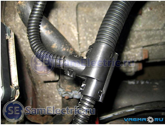
The branching of the wires hidden in the corrugation is carried out using a collapsible tee (photo 13)

I didn't have any triplets. I had to use tape, even though I don't like it. The edges of the tubes are inserted into each other and carefully wrapped.

For branching, there are cable heat-shrinkable cable gloves (photo 15)

Photo 15 - cable heat-shrinkable gloves
It's a great thing, but I've seen these in retail stores once, and then they are designed for large diameter cables. If you are a fan of your craft, you will surely want to use these products. They are in online stores (but you have to look), for example, the KBT plant (Kaluga) will soon produce such products (I advise you to visit the KBT catalog on their website).
Stripping

Photo 16 - Stripper
Implemented special tool- stripper (photo 16)
He cuts the insulation, not reaching the core, but so that it can be torn off and moved. I strongly doubt that someone uses such a tool in everyday life (for example, I don’t have one). Do not listen to someone who tells you “and I cut the insulation across the wire with side cutters / cutters / knife” this is done at your own peril and risk, you cannot be sure that the blade did not reach the wire cores. "By eye" it is very difficult to adjust the depth of the incision.
I do like this. But you need to be confident in your tool, hands and wire insulation! Yes, and after 10-20 such removals, corns begin to appear! (Note SamElectric.ru)

One of the stripping tools is a mounting knife, straight or with a heel (photo 17). With some skill, insulation can be used with a clerical knife instead of a straight mounting knife. The insulation is cut with chips, as if sharpening a pencil, but trying not to cut the wires.

I use a utility knife extensively. Especially when stripping cables. To do this, I cut the outer insulation lengthwise, trying not to cut the inner, individual one. And in a single wire I remove the insulation (when there are no wire cutters, or in difficult cases), cutting the insulation around.
Defense companies used insulation burners, which are similar to wood burning tools. red-hot nichrome wire insulation is burned in a circle and then removed. Suitable for MGTF and other wires. Similarly, you can remove the insulation with a soldering iron (photo 19). Minus - the smell and harmful fumes.

Photo 19 - Removing the insulation with a soldering iron.

Photo 19-2 - Removing the insulation with a soldering iron.
Soldering or crimping wires
In general, crimping is better in terms of vibration resistance. When soldering, at the point where the wires come out of the solder, they are more likely to break off if they are subjected to vibration (photo 20).

A properly made crimp is stronger than the wire itself, but how many people have a crimp at least for auto-terminals at home? That's right, no, I have too (but in general the crimps look like this - photo 21). So let's solder.


I have both a crimp and a stripper. I already wrote about crimping wires with tips.
Important: never use acidic fluxes when soldering wires, no matter how tempting it may sound. Because the wire is a capillary pump and you still can’t wash out the flux residues from there, no matter who tells you what. Soon there will be corrosion.
It is convenient to use rosin dissolved in alcohol. Pour this solution into a bottle with a brush, such as nail polish.
It is convenient to use flux LTI-120 with a brush. Or rosin in a jar, I write about it.
Connector covers
- protect the contacts inside from water and dust, provide mechanical adhesion of the connector body and wire. They are sealed or non-sealed.
In photo 22, the connector worked for a long time without a casing, the wires were often bent and moved, the cores were partially broken near the contacts (the wires were connected by crimping, but the reason for the malfunction was precisely in the absence of a casing).

Photo 22 - Connector without casing
Sealed casings are made of heat-shrinkable materials with an adhesive layer. The same tube, just a different shape. You can easily use a piece of regular tubing, but the fact is that the diameter of the back of the connector and the diameter of the cable have a very large difference that ordinary heat shrink at a ratio of 2:1 does not cover. Simply put, it will sit on the connector normally, and the wire will hang out. You can look for tubing with a shrink ratio of 3:1 or more. They do exist, but they cost more.

23 - Heat shrink connector cover
In photo 23, a piece of ordinary heat shrink was used, a corrugation of a larger diameter was taken (only 2 wires inside). It should be noted that the softening temperature of the corrugation is approximately equal to the shrinkage temperature of the tube, so you need to work with the burner quickly and carefully, trying not to overheat anything.

Photo 24-1 - Before and after

Photo 24-2 - new electrical harness installed
Sealing
If necessary, special mastic is poured inside the casing to seal the contacts. In private practice, you can use silicone automotive sealant. Large volume will dry for several days. If this is really necessary, try to be patient and pour in parts, or at least smear the critical parts with a thick layer.
Important: never use acid curing sealants, corrosion will not take long.

If you open the tube and the smell of acetic acid hits your nose, do not use it. If it does not smell, you can use it, it is alcohol-based neutral.
As a rule, acid sealants are cheaper (ABRO, RUNWAY), an honest manufacturer will indicate on the package - “Contains acetic acid”. If there is no such inscription, carefully read the composition and google each of the components. The composition of the sealant that I bought contained methyltriacetoxysilane - this is a reagent for vulcanizing rubbers, synthesized using acetic anhydride (I do not claim that this component is present in absolutely all acid sealants, please pay attention to the composition when buying).
After opening this tube, it began to smell acetic acid, although the manufacturer has indicated that it can be used for electrical connections. We will not tempt fate, we will leave it for less responsible nodes.

Bundle laying
The installation order is:
- we place the tourniquet in place, temporarily fix it with ties;
- connect all electrical connectors;
- we fix the bundle in place, starting from the connectors (for example, from the ends of the bundle, where there are smaller terminals to a large common connector).

The harness is secured in place with nylon cable ties. By the way, black ties are more resistant to external influences.
In photo 27 on the left you can see 2 metal clamps that attach the wires to the frame. They can be used, but on condition that the clamp does not fray the wire - locally wrap it with electrical tape, put on a piece of heat shrink, put something on it. Do not forget that the harness should not be pulled tight at the connectors, should not touch sharp corners, dangle too much, or touch very hot parts.
But what if the harness goes into the box and connects there?
This situation simply occurs when a brake light is connected:

The black contraption with a union nut in photo 28 is a plastic cable gland (gland). It is designed just for entering cables into various boxes. Such a thing costs no more than 20 rubles (for small wire diameters). There are metal cable glands (for harsh conditions and critical connections), but in stores they are at best made to order, the cost is already about 100 r per piece. In addition to the inputs, there are special penetrations and bushings.

Photo 29 - Cable entry on the wire in the analysis

The wire dangles in the connector (yes, anywhere), what else can be done?
If winding with various electrical tapes (PVC or fabric) and fixing with clamps does not suit you, then ...
There is such a wonderful thing - LETSAR silicone tape - electrical insulating heat-resistant self-adhesive rubber radiation vulcanization tape. It is a self-adhesive tape, vulcanized at room temperature. After two days, you get a piece of relatively soft rubber where you wound it.
In aircraft harnesses, it is just wound under rigid metal casings for better compression. I will not describe the properties in more detail, too much text. Sold in spools of 500 g, highly stretched when winding, the coil will last a very long time.
In general, it is worth looking for self-adhesive (self-vulcanizing) tapes of other brands, there is less packaging.
- OST 1 00723-74 Connection of negative wires to the body aircraft. Technical requirements
- GOST 23585-79 Installation of electrical radio-electronic equipment and devices. Technical requirements for cutting and connecting wire screens
- GOST 23586-96 Installation of electrical radio-electronic equipment and devices. Technical requirements for harnesses and their fastening
- GOST 23587-79 Technical requirements for cutting installation wires and fastening cores
- OST 1.01025-82 Shielding of wires, bundles, cables and metallization of aircraft. General technical requirements
Cable tie add-on
It's more practical than plastic ties(clamps) and electrical tape. The main advantage is that it is reusable!


