Structural requirements for bolted connections. Calculation and design of bolted connections Bolted connections of metal structures snip
The bolt connection consists of a bolt, nut, washer and fastened parts (Fig. 3.1). In fastened parts (Fig. 3.2 a) drill a hole with a diameter of (1.05 - 1.1) d, where d is the diameter of the bolt thread. A bolt is inserted into the hole, the end of which should extend outside the parts to be joined by about 1.3 d (Fig. 3.2 b).
A washer is put on the bolt (Fig. 3.2 in) and then screw on the nut (Fig. 3.2 G). The methodology for determining the dimensions required to create geometric models of a bolt, nut, and washer is presented earlier.
Screw terminals are common in the manufacturing industry. In addition to the traditional screw terminals on the market, we have spring loaded couplers, quick couplers or eye couplers. Screw connections mean high contact pressure and large contact surfaces. Screw couplings are the most recognized and most widely used wire connection technology. The screw connection is also great solution for wiring with large cross-sections.
Screw couplings remain one of the most popular and widely used solutions on the market. The reasons must be partly seen in the habits of installers - screw terminals have been dealt with for several decades, the industry has managed to pick up some habits. Screw connections are consistently rated for their high contact pressure, which contributes to safety and low voltage drop. Screw couplings are mainly used to create multi-wire connections.
Rice. 3.1. Connection of parts with a bolt
The estimated length of the bolt can be determined by the formula
l R = B 1 + B 2 + S + H + a + c, (1)
where AT 1 and B 2 - the thickness of the fastened parts; S - washer thickness; H- height of the nut; a- thread margin at the outlet of the nut (a = 0.2 d);With- chamfer height at the end of the bolt shaft (с = 0.15 d).
This type of connection covers wires with a cross section of approx. 0.08 mm². This is due to the design of the clamp. The wire is pressed against the contact rail with a screw and a terminal block. As the torque increases, the friction force is increased by the screw in the threaded connection. The quality of the screw clamp depends to a large extent on the installer, and the strength of the clamp - experience in this type of connection is also important. Please note that before commissioning after installation, check the condition of all connections, especially by tightening the screw terminals.
Substituting the values of all these quantities into the formula, we get:
l R \u003d B 1 + B 2 + 0.15d + 0.8d + 0.2d + 0.15d \u003d B 1 + B 2 + 1,3 d. (2)
The standard bolt length is selected from the normal range of lengths given in App. one.
Rice. 3.2. The sequence of creating a connection with a bolt
This minimizes the risk of failure such as a self-hardening screw due to vibration. Screw terminals should not be too tight to prevent the conductor from being deformed or to reduce its cross section. Among these types of products, we mainly highlight screw connectors for non-deformation cables - this is the simplest solution, mainly used for single-core cables. In these systems, the clamping force is shared by the current flow so that the type of material can be selected accordingly.
Biting deeper into the offer of manufacturers, we see, among others. Screw connections for universal use. This type of connection guarantees good contact and allows the connection of stranded wires. Screw housing provides a gas-tight connection; Thanks to the high contact pressure and the maximum range of cross-sections, the screw terminal allows the connection of stranded conductors. Other specially designed screw connections ensure a stable and secure connection even in sensitive areas.
When drawing a bolted connection, consider the following:
On the main image, the bolt head and nut are usually shown with three faces.
According to GOST 2.305-2008, bolts, screws and studs in a longitudinal section are depicted as not dissected. On assembly drawings, as a rule, nuts and washers are also depicted as not dissected.
The tension spring acts on the cord constantly with equal force, regardless of the conditions. Lead connection saves valuable space and simplifies wiring. We can't forget about direct plug-in connections - the hard wires are simply connected directly to the terminal. Installation work is faster and easier, and the screwdriver only needs to pull out the cord. An interesting solution is the quick connection technology, which allows you to connect wires without stripping the insulation.
This means a significant acceleration of work - from what one manufacturer gives, up to 60%. Only one standard screwdriver. Threaded screw terminals are used primarily if we want to focus all the circuits that make up electrical installation at one point, usually in a terminal strip, rack or junction box. Terminal blocks are already standard in distribution systems in modern receiving installations. Due to this, electrical equipment takes less space, which facilitates the operation and operation of the installation.
Adjacent parts are hatched with an inclination in different directions. The slope of the hatching for the same part must be in the same direction on all images.
An example of determining the main geometric parameters of the parts included in the connection with a bolt
Initial data determined by option (Table 1.1, Appendix 1):
In the beginning, serial connectors were made with a certain number of connection points for direct mounting, which meant that it was necessary to determine in advance what types of terminals were needed. The solution is currently in use. Modular terminals for individual consistent development - they allow terminals to be adapted to new or existing ones. Serial connectors have expanded significantly - manufacturers offer new solutions, both with screw connections, a spring cage, a straight spring, and a quick connector.
Thread - M12;
The thickness of the fastened plates is B 1 = 10 mm, B 2 = 15 mm.
Bolt and washer of the first execution, nut - of the second.
Definition of bolt parameters
Bolt lengthl
The estimated length of the bolt is determined by the formula (2):
l R = B 1 + B 2 + 1,3 d .= 10+15+1.3 12=40.6.
Regardless of the connector type, the row can be equipped with the same accessories and freely assembled. Screw terminals can be used to connect 1 or 2 wires or wire wires with cross sections from 0.2 to 300 mm² - values vary from manufacturer to manufacturer. screw terminal blocks thanks to the maintenance-free separator screw for a gas-tight connection.
Aluminum wire terminals - also with screws
Manufacturers of screw connections met the expectations of installers working on aluminum wires, especially in the range of 16 mm² and above. Aluminum is primarily chosen for its lower price and lower weight. However, we cannot forget that although the use of this material in the energy industry is justified, some basic conditions for its use must be met. Let's keep in mind that aluminum is more susceptible to deformation under pressure, an oxide layer forms on the surface of the insulated strands of this material, which under certain conditions increases the resistance between the conductor and the clamp, which can cause a strong heating of the contact.
App. 1 in the first column ( l ) tab. 1.2 from a number of standard bolt lengths, we determine that the size 40,6 is between lengths 40 and 45. We choose the middle one - 40 mm.
So the bolt length l = 40.
Thread length determined from Table. 1.2 app. 1 by nominal thread diameter d and bolt length l , equal to 66 mm.
As a result, the aluminum wires are connected to the rail connectors in one of two ways: directly or by overlapping and pressing through the conduit and inserting the pressed element into the terminal. Rail sleeves with cable clamps will be used for direct connection of round solid aluminum wires - this is possible due to the shape coupling. However, we cannot forget to remove the oxide layer from the insulated channel and apply neutral Vaseline or lubricant.
The voltage drop is measured at a distance less than or equal to 10 mm from the center of the terminal. The company faces a rather difficult task: when one Switchgear or installation must be shipped with screw terminals; The other, for example, must be designed with push-in type spring clips. Universal connector - provides good contact and allows you to connect multiple wires. If we want to make a very general characterization, the materials that make up the clamps can be divided into insulating and conductive.
So the thread length l 0 = 30 mm.
The turnkey size of the bolt head is determined from Table. 1.3 app. 1 according to the nominal thread diameter (d = 12 mm).
Turnkey size S = 19 mm.
Bolt head height k = 7.5 mm. The dimensions of the chamfer of the bolt head are given in the drawing app. one.
Determination of nut parameters
The insulating material supports and maintains the conductive elements in a stable position. First of all, the maximum resistance of the material to the environment. The design of the conductive part depends on the type, size and function to be performed. For the production of terminals is used, in particular. Polyamide resins, better known as nylon. Nylon-based materials feature high temperature resistance, high hardness, abrasion resistance and harsh working conditions. In the event of a fire, we will appreciate its self-extinguishing properties, and the gases emitted during combustion have a low pollutant index.
The parameters of the nut are determined according to the table app. 3 according to the nominal thread size (d = 12 mm):
Turnkey size S = 19 mm;
Nut height H= 10 mm;
Definition geometric parameters washers
The geometric parameters of the washer are determined according to the table app. 4 according to the nominal thread size (d = 12 mm):
Hole diameter d 1 = 13 mm.
Organic strength, fat and oil products are also important. In recent years, spring clamps have appeared on the market and since then the attention of manufacturers has turned to this type of product. Although screw connections may vary in material parameters or some improvements, the design has remained virtually unchanged over the years, and designers are paying more attention to the development of the field of spring couplings. This is primarily due to the fact that the spring force is automatically adjusted by the cross section of the wire, so that the wire is not damaged.
There is no need to increase the clamping force. In addition, spring connections are more impact resistant, so there is no way to loosen the clamp; The lower risk of error is also reduced. Also, spring clips "win" with screws when it comes to assembly time. The installation is essentially toolless - the cord is inserted into the clamp, and after the spring has disengaged from the connector's automatic clamp.
Outer diameter d 2 = 24 mm.
Washer thickness S = 2.5 mm.
Determination of the geometric parameters of the fastened plates
Plate height set: B 1 = 10 mm, B 2 = 15 mm.
We assume the width and height of both plates to be the same. Let the length L = 3S, and the width h = 2S, where S is the turnkey size.
From this it follows that L=3 19 = 57, round off and take L = 60 mm; h = 2 19 = 38, round off and take h = 40 mm.
This is due to a number of advantages that screw terminals have. The most important of these is their versatility. He has screwed a screw every time in his life, so most people intuitively know how to connect wires in screw terminals. It is also important here that the conductive elements of the couplings have the same alloy that is closest to the pipeline. True, screw connectors are not the fastest in terms of connection time, but this time can be minimized using cordless or pneumatic screwdrivers.
In addition, there are versions of screw connectors with wired connectors. In a conventional screw connection, friction up to 90% affects the effectiveness of the clutch. New defense based on stress, not friction. This protects connections, especially those that are subject to vibration and other mechanical stress. The gasket consists of two parts. One has radial cuts and the other has wedges. Gaskets are wound, allowing the customer to assemble faster and avoid missing items.
The diameter of the hole in the plates is determined by the formula:
d resp. = 1.1 d = 1.1 12 = 13.2 mm.
rounded d resp. = 13 mm.
STO NOSTROY 2.10.76-2012
STANDARD OF THE NATIONAL ASSOCIATION OF BUILDERS
Building structures metal
BOLT CONNECTIONS
Rules and control of installation, requirements for the results of work
metal structures. Bolted connections. Rules, construction control, work output requirements
Type of work 10.1-10.6 by order of the Ministry of Regional Development of Russia dated December 30, 2009 N 624.
Foreword
1 DEVELOPED by Closed Joint Stock Company "TsNIIPSK named after Melnikov"
2 SUBMITTED FOR APPROVAL by the Industrial Construction Committee of the National Association of Builders, protocol dated June 09, 2012 N 18
3 APPROVED AND PUT INTO EFFECT by the Decision of the Council of the National Association of Builders, protocol dated June 22, 2012 N 30
4 INTRODUCED FOR THE FIRST TIME
Introduction
This standard was developed as part of the Standardization Program of the National Association of Builders and is aimed at implementing the Town Planning Code of the Russian Federation, Federal Law of December 27, 2002 N 184-FZ "On Technical Regulation", Federal Law of December 30, 2009 N 384-FZ " Technical Regulations on the Safety of Buildings and Structures", Order of the Ministry of Regional Development of the Russian Federation of December 30, 2009 N 624 "On approval of the List of types of work on engineering surveys, on the preparation project documentation, for the construction, reconstruction, overhaul of capital construction facilities that affect the safety of capital construction facilities ".
The standard was developed in the development of SP 70.13330.2012 "SNiP 3.03.01-87 Bearing and enclosing structures" in terms of the installation of metal structures with bolted joints intended for buildings and structures various levels responsibility.
When developing the standard, the standard STO 0051-2011 "Steel construction structures. Bolted connections. Manufacturing and installation" was used, developed by CJSC "TsNIIPSK named after Melnikov" and JSC NIPI "Promstalkonstruktsiya".
1 area of use
1 area of use
1.1 This standard applies to the assembly connections of building metal structures using bolts intended for stationary, collapsible and mobile buildings and structures for various purposes, perceiving permanent, temporary and special loads (moving, vibration, explosive, seismic, etc.) in climatic areas with a design temperature of up to minus 60 °C, in areas with seismicity up to 9 points, operated both in slightly aggressive and in medium and aggressive environments with the use of protective metal and paint coatings.
1.2 This standard establishes requirements for the performance and quality control of bolted connections during the installation of metal building structures using bolts, including high-strength ones, both with controlled tension and without controlled tension of bolts.
2 Normative references
This standard uses normative references to the following standards and codes of practice:
GOST 9.307-89 one system protection against corrosion and aging. Hot zinc coatings. General requirements and control methods
GOST 2601-84 Welding of metals. Terms and definitions of basic concepts
GOST 5915-70* Hexagon nuts of accuracy class B. Design and dimensions
GOST 5927-70* Hexagon nuts of accuracy class A. Design and dimensions
GOST 7798-70* Hexagon head bolts of accuracy class B. Design and dimensions
GOST 7805-70* Hexagon head bolts of accuracy class A. Design and dimensions
GOST 10605-94 Hexagon nuts with a thread diameter over 48 mm, accuracy class B. Specifications
GOST 11371-78* Washers. Specifications
GOST 18123-82* Washers. General specifications
GOST 18126-94 Bolts and nuts with a thread diameter over 48 mm. General specifications
GOST 20072-74 Heat-resistant steel. Specifications
GOST 23118-2012 Steel building structures. General specifications
________________
GOST 23118-99.
GOST 23683-89 Petroleum solid paraffins. General specifications
GOST 24379.0-2012 Foundation bolts. General specifications
________________
It is put into effect on the territory of the Russian Federation from July 01, 2013 instead of GOST 24379.0-80.
GOST 24379.1-2012 Foundation bolts. Design and dimensions
________________
It is put into effect on the territory of the Russian Federation from July 01, 2013 instead of GOST 24379.1-80.
GOST 24997-2004 Gauges for metric threads. Tolerances
GOST 25726-83 Manual alphabetic and digital stamps. Types and basic dimensions
GOST 28548-90 Steel pipes. Terms and Definitions
GOST R 8.752-2011 State system ensuring the uniformity of measurements. State verification scheme for torque measuring instruments
________________
GOST 8.541-86.
GOST R 9.316-2006 Unified system of protection against corrosion and aging. Coatings are thermal diffusion zinc. General requirements and control methods
GOST R 51254-99 Mounting tool for normalized tightening of threaded connections. Keys are momentary. General specifications
GOST R 51634-2000 Motor and tractor oils. General specifications
GOST R 52627-2006 Bolts, screws and studs. Mechanical properties and test methods
________________
The document is not valid on the territory of the Russian Federation. GOST R ISO 898-1-2011 is valid, hereinafter in the text. - Database manufacturer's note.
GOST R 52628-2006 Nuts. Mechanical properties and test methods
GOST R 52643-2006 High-strength bolts and nuts and washers for metal structures. General specifications
GOST R 52644-2006 High-strength hexagon head bolts with increased turnkey size for metal structures. Specifications
GOST R 52645-2006 High-strength hexagon nuts with increased turnkey size for metal structures. Specifications
GOST R 52646-2006 Washers for high-strength bolts for metal structures. Specifications
GOST R 53664-2009 High-strength cylindrical and conical bolts for bridge building, nuts and washers for them. Specifications
GOST R ISO 8992-2011 Fasteners. General requirements for bolts, screws, studs and nuts
________________
It is put into effect on the territory of the Russian Federation from January 01, 2013 instead of GOST 1759.0-87.
GOST R ISO 16047-2009 Fasteners. Torque and Preload Tests
SP 16.13330.2011 "SNiP II-23-81* Steel structures"
SP 28.13330.2012 "SNiP 2.03.11-85 Protection of steel structures against corrosion"
SP 43.13330.2011 "SNiP 2.09.03-85 Constructions of industrial enterprises"
_______________
SP 43.13330.2012, hereinafter in the text. - Database manufacturer's note.
SP 48.13330.2011 "SNiP 12-01-2004 Organization of construction"
SP 49.13330.2010 "SNiP 12-03-2001 Occupational safety in construction. Part 1. General requirements"
_______________
Currently, there is no information in official sources about the adoption of this document, mentioned hereinafter in the text. - Database manufacturer's note.
SP 70.13330.2012 "SNiP 3.03.01-87 Bearing and enclosing structures"
SP 128.13330.2012 "SNiP 2.03.06-85 Aluminum structures"
SP 131.13330.2011 "SNiP 23-01-99* Building climatology"
________________
On the territory of the Russian Federation, SP 131.13330.2012 is in force, hereinafter in the text. - Database manufacturer's note.
NOTE When using this standard, it is advisable to check the validity of the referenced standards in information system common use- on the official websites of the national body of the Russian Federation for standardization and NOSTROY on the Internet or according to annually published information indexes published as of January 1 of the current year. If the reference document is replaced (changed), then when using this standard, you should be guided by the new (changed) document. If the referenced document is canceled without replacement, the provision in which the link to it is given applies to the extent that this link is not affected.
3 Terms and definitions, designations and abbreviations
3.1 This standard uses terms in accordance with the Town Planning Code, GOST 2601, GOST R ISO 16047, GOST 28548, SP 16.13330, SP 70.13330, SP 128.13330.
3.2 The following symbols and abbreviations are used in this standard:
KM - metal structures;
KMD - metal detailing structures;
RD - working documentation;
Gross bolt cross-sectional area, mm;
Net bolt cross-sectional area, mm;
Nominal bolt diameter, mm;
Nominal hole diameter, mm;
Bolt tightening factor;
Reliability coefficient;
Friction coefficient;
Length, cm;
Bolt torque, N m (kgf m);
Axial tension force of bolts, kN (tf);
The smallest tensile strength of the bolt, N/mm (kgf/mm);
Cargo weight, N (kgf);
Thickness, mm
4 Applications for bolted connections
4.1 Bolted connections are allowed to be used for all groups of steel structures specified in SP 16.13330 (Appendix B) and aluminum structures provided for by SP 128.13330.
In accordance with SP 70.13330, the following types of bolted connections are used:
Bolted connections with controlled tension;
Bolted connections without controlled tension.
4.2 Bolted connections are considered in the standard:
Friction (shear-resistant), in which shear forces are perceived by friction forces acting on the contact surfaces of the elements to be connected as a result of bolt tension on the design force;
Shear, in which shear forces are perceived by the resistance of the bolts to shear, and the connected elements - to crushing;
Friction-shear, which takes into account the entire set of resistances: bolts - shear, connected elements - crushing and friction;
Flanged, in which bolts tightened to design reinforcement work in tension with rigid flanges or in tension with bending with flexible flanges;
Bolt-welded, in which shear forces are perceived jointly by friction forces from bolt tension and welds;
Bolt riveting, in which shear forces are perceived jointly by friction forces from the tension of the bolts and rivets.
4.3 Friction (shear-resistant) joints are used in structures and their elements in which residual shear movements are not allowed, operating in particularly difficult conditions or directly exposed to alternating, dynamic, vibration or moving loads, including in structures designed for fatigue.
4.4 Shear connections are used in structures operating under static load, as well as in auxiliary structures of buildings and structures.
4.5 Friction shear joints are used in structures operating under static load, as well as under the influence of alternating forces, when the smaller of them can be transmitted by friction forces.
4.6 Flange connections are used in structures and their elements subject to tension, compression, tension with bending, local transverse forces, including moving, vibration or other types of loads with a number of loading cycles up to 10 and a stress asymmetry factor of 0.8.
4.7 Bolt-welded joints (on bolts and welding) are used to strengthen structures with friction and flange joints by welding parts or additional installation of high-strength bolts with preload in welded joints.
4.8 Bolt-rivet connections (on bolts and rivets) are used in the repair of riveted structures, in which the decrease in bearing capacity is compensated by friction forces after replacing defective rivets with high-strength bolts tightened to the design force.
4.9 The strength classes of bolts without coating or with protective metal coatings are taken depending on the climatic region for the construction of a building or structure, established by SP 131.13330, operating conditions of structures (calculated or not calculated for fatigue), operating conditions of bolts (for shear or tension).
Strength classes, steel grades, working conditions and requirements for bolts are given in table 1.
Table 1
|
Design temperature of the climatic area of construction, °С |
bolt conditions |
Bolt strength class |
Bolt steel grade |
Bolt Requirements |
|
In structures not designed for fatigue |
||||
|
stretch or shear |
||||
|
40X, 20G2R |
||||
|
high strength 10.9 |
||||
|
stretching |
||||
|
stretching |
table 3 GOST R 52627 |
|||
|
high strength 10.9 |
||||
|
stretching |
table 3 GOST R 52627, with a guaranteed impact strength characteristic |
|||
|
high strength 10.9 |
table 3 GOST R 52644, version HL |
|||
|
________________ |
||||
4.10 For bolted connections, as a rule, bolts, nuts and washers (hereinafter referred to as fasteners) without coating are used.
Fasteners with protective metal coatings must be used for connections:
Structural elements with protective metal coatings applied by hot or thermal spraying (zinc or aluminum coatings);
Elements of antenna structures, masts and supports of power lines;
Structural elements operated in a medium aggressive environment according to the classification of SP 28.13330, together with paint and varnish coatings;
Elements of railway, urban and surface bridges, gas pipelines;
Structural elements operated in the marine atmosphere.
Note - For bolted connections of structural elements operating in the marine atmosphere, it is recommended to use cadmium-coated fasteners.
4.11 In accordance with the classification of the aggressiveness of the environment given in SP 28.13330, as a rule, thermal diffusion zinc coating according to GOST R 9.316 or hot zinc coating according to GOST 9.307 using centrifugation and cutting nuts using taps is used as a protective metal coating for fasteners technical customer:
In slightly aggressive environments - as an independent coating;
In moderately aggressive environments - with additional paintwork.
4.12 For structures operated in slightly aggressive environments, it is allowed to use fasteners with metal coatings in accordance with GOST R ISO 8992: zinc chromated, cadmium chromated, zinc with an additional paint and varnish coating.
4.13 For structures operated in aggressive environments, bolts, nuts and washers are used from corrosion-resistant, heat-resistant and heat-resistant steels according to GOST R ISO 8992, except for heat-resistant steels, which are used according to GOST 20072.
5 Requirements for fasteners
5.1 For joints of building metal structures, the following are used:
Hexagon head bolts of accuracy class B (normal accuracy) in accordance with GOST 7798 or accuracy class A (higher accuracy) in accordance with GOST 7805 with a large thread pitch, diameter from 12 to 48 mm, strength classes 5.6, 5.8, 8.8, 10.9, 12.9 with technical requirements in accordance with GOST R 52627;
Hex nuts of accuracy class B (normal accuracy) according to GOST 5915 or accuracy class A (increased accuracy) according to GOST 5927, strength classes 5, 8, 10, 12 with technical requirements according to GOST R 52628;
Round washers for them in accordance with GOST 11371, execution of 1 accuracy class A with technical requirements in accordance with GOST 18123.
5.2 High-strength bolts, nuts and washers should be used, respectively, in accordance with GOST R 52644, GOST R 52645 and GOST R 52646 with technical requirements according to GOST R 52643 with a diameter of 16 to 48 mm, strength classes 10.9 and 12.9.
"Standard of the organization BOLTED CONNECTIONS Rules and control of installation, requirements ..."
-- [ Page 1 ] --
Organization Standard
Building structures metal
BOLT CONNECTIONS
Rules and control of installation, requirements
to the results of work
STO NOSTROY 2.10.76-2012
EDITION OFFICIAL
Moscow 2013
NATIONAL ASSOCIATION OF BUILDERS
Organization Standard
Building structures metal
BOLT CONNECTIONS
Rules and control of installation, requirements for the results of work STO NOSTROY 2.10.76-2012 MelnikovLimited Liability Company BST Publishing House
Moscow 2013 STO NOSTROY 2.10.76-2012 Foreword 1 DEVELOPED by Closed Joint Stock Company TsNIIPSK im. Melnikov
2 SUBMITTED by the Industrial Construction Committee for APPROVAL to the National Association of Builders, minutes dated June 09, 2012.
No. 18 3 APPROVED AND INTRODUCED BY THE DECISION OF THE COUNCIL OF THE NATIONAL BUILDERS ASSOCIATION, Minutes No. 30 dated June 22, 2012
4 INTRODUCED FOR THE FIRST TIME
© National Association of Builders, 2012 Distribution of this standard is carried out in accordance with applicable law and in compliance with the rules established by the National Association of Builders II STO NOSTROY 2.10.76-2012 Contents Introduction
1 area of use
6 Requirements for structures with bolted connections
7 Making Bolt Connections with Controlled Tension..................................17
7.1 Assembly requirements for connections
7.2 Preparing bolts, nuts and washers
7.3 Preparation of contact surfaces
7.4 Assembling connections
7.5 Bolt tension
8 Making connections on bolts without controlled tension .................................29 9 Quality control, acceptance and sealing of bolted connections ................................30 10 performance of work
Appendix A (informative) Form of a journal for performing field connections on tension-controlled bolts ..................................34 Appendix B (recommended) Training program for installers and engineers on the implementation and acceptance of bolted connections (20 hours). Form of certificate ............... 39 Appendix B (recommended) Determination of the torque factor Kz
Appendix E (informative) Typical workflow
– – –
bolted connections
Bibliography
– – –
This standard was developed as part of the Standardization Program of the National Association of Builders and is aimed at implementing the Town Planning Code of the Russian Federation, Federal Law No.
No. 184-FZ “On Technical Regulation”, Federal Law No. 384-FZ of December 30, 2009 “Technical Regulations on the Safety of Buildings and Structures”, Order No. 624 of the Ministry of Regional Development of the Russian Federation of December 30, 2009 “On Approval of the List types of work on engineering surveys, preparation of project documentation, construction, reconstruction, overhaul of capital construction facilities that affect the safety of capital construction facilities.
The standard was developed in the development of SP 70.13330.2012 "SNiP 3.03.01-87 Bearing and enclosing structures" in terms of the installation of metal structures with bolted joints intended for buildings and structures of various levels of responsibility.
When developing the standard, the standard STO 0051-2011 “Building steel structures. Bolted connections. Manufacturing and installation”, developed by CJSC “TsNIIPSK im. Melnikov" and OAO NIPI "Promstalkonstruktsiya".
The main goal of developing the standard is to create a modern regulatory framework for the implementation of assembly joints of metal structures on high-strength bolts with controlled tension, as well as on bolts of all strength classes without controlled tension.
– – –
1 area of use
1.1 This standard applies to the assembly connections of building metal structures using bolts intended for stationary, collapsible and mobile buildings and structures for various purposes, perceiving permanent, temporary and special loads (moving, vibrational, explosive, seismic, etc.) in climatic regions with a design temperature of up to minus 60 ° C, in regions with a seismicity of up to 9 points, operated both in slightly aggressive and medium aggressive and aggressive environments with the use of protective metal and paint coatings.
1.2 This standard establishes requirements for the performance and quality control of bolted connections during the installation of metal building structures using bolts, including high-strength ones, both with controlled tension and without controlled tension of bolts.
Official publication STO NOSTROY 2.10.76-2012
– – –
This standard uses normative references to the following standards and codes of practice:
GOST 9.30789 Unified system of protection against corrosion and aging.
Hot zinc coatings. General requirements and control methods GOST 260184 Welding of metals. Terms and definitions of basic concepts GOST 591570* Hexagon nuts of accuracy class B. Design and dimensions GOST 592770* Hexagon nuts of accuracy class A. Design and dimensions GOST 779870* Hexagon head bolts of accuracy class B. Design and dimensions GOST 780570* Hexagon head bolts accuracy class A. Design and dimensions GOST 1060594 Hexagon nuts with a thread diameter over 48 mm accuracy class B. Specifications GOST 1137178* Washers. Specifications GOST 1812382* Washers. General specifications GOST 1812694 Bolts and nuts with a thread diameter over 48 mm. General specifications GOST 2007274 Heat-resistant steel. Specifications GOST 2311820121) Steel building structures. General specifications GOST 2368389 Petroleum solid paraffins. General specifications GOST 24379.020122) Foundation bolts. General technical conditions It is put into effect on the territory of the Russian Federation from July 01, 2013 instead of 1) GOST 23118–99.
It is put into effect on the territory of the Russian Federation from July 01, 2013 instead of 2) GOST 24379.0–80.
STO NOSTROY 2.10.76-2012 GOST 24379.120121) Foundation bolts. Design and dimensions GOST 249972004 Gauges for metric threads. Tolerances GOST 2572683 Brands manual alphabetic and digital. Types and main dimensions GOST 2854890 Steel pipes. Terms and definitions GOST 8.75220112) State system for ensuring the uniformity of measurements. State verification scheme for torque measuring instruments GOST R 9.3162006 Unified system of protection against corrosion and aging. Coatings are thermal diffusion zinc. General requirements and methods of control GOST R 5125499 Mounting tool for standard tightening threaded connections. Keys are momentary. General specifications GOST R 516342000 Autotractor motor oils. General specifications GOST R 526272006 Bolts, screws and studs. Mechanical properties and test methods GOST R 526282006 Nuts. Mechanical properties and test methods GOST R 526432006 High-strength bolts and nuts and washers for metal structures. General specifications GOST R 526442006 High-strength hexagon head bolts with increased turnkey size for metal structures. Specifications GOST R 526452006 High-strength hexagon nuts with increased turnkey size for metal structures. Specifications GOST R 526462006 Washers for high-strength bolts for metal structures. Specifications GOST R 536642009 High-strength cylindrical and conical bolts It is put into effect on the territory of the Russian Federation from July 01, 2013 instead of 1) GOST 24379.1-80.
It is put into effect on the territory of the Russian Federation from January 01, 2013 instead of 2) GOST 8.54186.
STO NOSTROY 2.10.76-2012 for bridge construction, nuts and washers for them. Specifications GOST R ISO 899220111) Fasteners. General requirements for bolts, screws, studs and nuts GOST R ISO 160472009 Fasteners. Tests of torque and preload force SP 16.13330.2011 "SNiP II-23-81* Steel structures"
SP 28.13330.2012 "SNiP 2.03.11-85 Protection of steel structures against corrosion"
SP 43.13330.2011 "SNiP 2.09.03-85 Constructions of industrial enterprises"
SP 48.13330.2011 "SNiP 12-01-2004 Organization of construction"
SP 49.13330.2010 “SNiP 12-03-2001 Occupational safety in construction.
Part 1. General requirements"
SP 70.13330.2012 "SNiP 3.03.01-87 Bearing and enclosing structures"
SP 128.13330.2012 "SNiP 2.03.06-85 Aluminum structures"
SP 131.13330.2011 "SNiP 23-01-99* Building climatology"
Note - When using this standard, it is advisable to check the effect of reference standards in the public information system - on the official websites of the national body of the Russian Federation for standardization and NOSTROY on the Internet or according to annually published information indexes published as of on January 1st of the current year. If the reference document is replaced (changed), then when using this standard, you should be guided by the new (changed) document.
If the referenced document is canceled without replacement, the provision in which the link to it is given applies to the extent that this link is not affected.
3 Terms and definitions, designations and abbreviations
3.1 This standard uses the terms in accordance with the Town Planning Code, GOST 2601, GOST R ISO 16047, GOST 28548, SP 16.13330, Entered into force on the territory of the Russian Federation from January 01, 2013 instead of 1) GOST 1759.087.
STO NOSTROY 2.10.76-2012 SP 70.13330, SP 128.13330.
3.2 The following symbols and abbreviations are used in this standard:
KM - metal structures;
KMD - metal detailing structures;
RD - working documentation;
Аb bolt gross area, mm2;
Аbn bolt net area, mm2;
db nominal bolt diameter, mm;
do nominal hole diameter, mm;
Kz bolt tightening factor;
Kn coefficient of reliability;
µ friction coefficient;
length, cm;
Mz bolt torque, N m (kgf m);
P axial bolt tension force, kN (tf);
Rbun is the smallest tensile strength of the bolt, N/mm2 (kgf/mm2);
g cargo weight, N (kgf);
n readings of the measuring device;
t thickness, mm.
4 Applications for bolted connections
4.1 Bolted connections may be used for all groups of steel structures specified in SP 16.13330 (Appendix B) and aluminum structures provided for by SP 128.13330.
In accordance with SP 70.13330, the following types of bolted connections are used:
STO NOSTROY 2.10.76-2012
Bolted connections with controlled tension;
Bolted connections without controlled tension.
4.2 Bolted connections are considered in the standard:
Friction (shear-resistant), in which shear forces are perceived by friction forces acting on the contact surfaces of the elements to be connected as a result of bolt tension on the design force;
Shear, in which shear forces are perceived by the resistance of the bolts to shear, and the connected elements - to crushing;
Friction-shear, which takes into account the entire set of resistances: bolts - shear, connected elements - crushing and friction;
Flanged, in which bolts tightened to design reinforcement work in tension with rigid flanges or in tension with bending with flexible flanges;
Bolt-welded, in which shear forces are perceived jointly by friction forces from bolt tension and welds;
Bolt riveting, in which shear forces are perceived jointly by friction forces from the tension of the bolts and rivets.
4.3 Friction (shear-resistant) joints are used in structures and their elements in which residual shear movements are not allowed, operating in particularly difficult conditions or directly exposed to alternating, dynamic, vibration or moving loads, including in structures designed for fatigue.
4.4 Shear connections are used in structures operating under static load, as well as in auxiliary structures of buildings and structures.
4.5 Friction shear joints are used in structures operating under static load, as well as under the influence of alternating forces, when the smaller of them can be transmitted by friction forces.
4.6 Flange connections are used in structures and their elements subject to tension, compression, tension with bending, local transverse forces, including moving, vibration or other types of loading.
– – –
4.10 For bolted connections, as a rule, bolts, nuts and washers (hereinafter referred to as fasteners) without coating are used.
Fasteners with protective metal coatings must be used for connections:
Structural elements with protective metal coatings applied by hot or thermal spraying (zinc or aluminum coatings);
Elements of antenna structures, masts and supports of power lines;
STO NOSTROY 2.10.76-2012
Structural elements operated in a medium aggressive environment according to the classification of SP 28.13330, together with paint and varnish coatings;
Elements of railway, urban and surface bridges, gas pipelines;
Structural elements operated in the marine atmosphere.
N o t e - For bolted connections of structural elements operated in the marine atmosphere, it is recommended to use fasteners with cadmium coating.
4.11 In accordance with the classification of the aggressiveness of the environment given in SP 28.13330, as a protective metal coating of fasteners, as a rule, thermal diffusion zinc coating according to GOST R 9.316 or hot zinc coating according to GOST 9.307 is used using centrifugation and cutting nuts using taps on request technical customer:
In slightly aggressive environments as an independent coating;
In moderately aggressive environments - with an additional paint and varnish coating.
4.12 For structures operated in slightly aggressive environments, it is allowed to use fasteners with metal coatings in accordance with GOST R ISO 8992: zinc chromated, cadmium chromated, zinc with an additional paint and varnish coating.
4.13 For structures operated in aggressive environments, bolts, nuts and washers are used from corrosion-resistant, heat-resistant and heat-resistant steels according to GOST R ISO 8992, except for heat-resistant steels, which are used according to GOST 20072.
5 Requirements for fasteners
5.1 For joints of building metal structures, the following are used:
Hexagon head bolts of accuracy class B (normal accuracy) in accordance with GOST 7798 or accuracy class A (increased accuracy) in accordance with GOST 7805 with coarse thread pitch, diameter from 12 to 48 mm, strength classes 5.6, 5.8, 8.8, STO NOSTROY 2.10.76 -2012 10.9, 12.9 with technical requirements according to GOST R 52627;
Hex nuts of accuracy class B (normal accuracy) in accordance with GOST 5915 or accuracy class A (increased accuracy) in accordance with GOST 5927, strength classes 5, 8, 10, 12 with technical requirements in accordance with GOST R 52628;
Round washers for them in accordance with GOST 11371, execution of 1 accuracy class A with technical requirements in accordance with GOST 18123.
5.2 High-strength bolts, nuts and washers should be used, respectively, in accordance with GOST R 52644, GOST R 52645 and GOST R 52646 with technical requirements in accordance with GOST R 52643 with a diameter of 16 to 48 mm of strength classes 10.9 and 12.9.
5.3 Marking of bolts and nuts must contain the stamp of the manufacturer and the strength class of the product. On high-strength bolts, the melting symbol is additionally indicated, the letter S, indicating the increased size of the turnkey head, and the letters ХЛ for northern-style bolts.
5.4 According to GOST R 52627 (section 3), the bolt strength class marking consists of two digits - the first corresponds to 1/100 of the nominal value of the tensile strength, N/mm2, the second corresponds to 1/10 of the ratio of the nominal value of the yield strength to the tensile strength, %. The product of these two figures corresponds to 1/10 of the nominal value of the yield strength, N/mm2.
5.5 The property class of nuts with a nominal height equal to or greater than 0,8 d (where d is the nominal thread diameter) is indicated by a number indicating largest class the strength of the bolt with which they can be mated in connection.
5.6 Fasteners intended for various types of connections (see 4.2) are given in table 2.
5.7 The design, dimensions and steel grades for foundation bolts are used in accordance with GOST 24379.0 and GOST 24379.1.
5.8 Nuts for foundation bolts made of VSt3sp2 and grade 20 steels, up to 48 mm in diameter, should be taken in accordance with GOST 5915 strength class 4; for foundation bolts made of steel grades 09G2S and 10G2S1 - strength class and a certificate of the established form indicating the results of acceptance tests and after input control for compliance with the requirements of GOST R 52643, GOST R 52644, GOST R 52645 and GOST R 52646 (see 7.1.4).
5.12 It is allowed to use high-strength bolts of strength class
10.9 with a guaranteed tightening torque for threaded connections according to TU 1282-162-02494680-2007.
6 Requirements for structures with bolted connections
6.1 Metal structures with bolted connections are made in accordance with the working documentation of KM (metal structures) and KMD (metal detailing structures), the manufacturer's technological documentation, SP 53-101-98, GOST 23118, taking into account the requirements of SP 70.13330, SP 28.13330 .
6.2 Installation of metal structures is carried out in accordance with the requirements of KM and KMD, SP 70.13330, sections 7 and 8 of this standard.
6.3 In general terms, explanatory note or on the KM drawings, as a rule, should be indicated:
Types of connections;
Nominal diameters of holes and bolts;
Standards for bolts, nuts and washers;
Strength classes of bolts and nuts;
Axial tension forces of bolts;
Way of regulation and control of axial tension forces of bolts;
Method of preparation of contact surfaces with indication of the calculated value of the coefficient of friction;
Parts and areas that are not subject to priming or painting at the enterprise - the manufacturer of metal structures;
Additional requirements for the manufacture and installation of metal structures STO NOSTROY 2.10.76-2012;
Regulatory documents for the manufacture and installation of metal structures;
Guidelines for anticorrosive protection of metal structures.
6.4 Depending on the degree of responsibility of individual groups of steel structures of buildings and structures, as well as on the conditions of their operation and the climatic region of construction, for structural elements with bolted joints, sheet and shaped steel should be used in accordance with SP 16.13330 (Appendix B).
6.5 For aluminum structures, aluminum grades and conditions should be used in accordance with SP 128.13330.
6.6 For flanges subject to tension, bending or their combined action, sheet steel with guaranteed mechanical properties in the direction of the rolled thickness shall be used, taking into account the requirements of SP 16.13330 (section 13 and clause 15.9).
6.7 The applied welding technology and welding consumables in accordance with SP 16.13330 (clause 5.4) must ensure the values of the tensile strength of the weld metal not lower than the standard values of the tensile strength Run of the base metal.
6.8 Bolts, nuts and washers intended for installation, as a rule, are supplied by manufacturers of metal structures. Estimated consumption of fasteners is given in VSN 428-81.
6.9 In the manufacture of structures at the assembly site, the used rolled products, before being put into production, must be checked for compliance with the accompanying documentation, the absence of unacceptable bends, local dents, cracks, delaminations, deviations from geometric dimensions.
6.10 Cutting blanks of shaped and sheet metal is allowed both mechanically and thermally. At the same time, the edges of structural elements working in tension, as well as those made of steel with a normative yield limit STO NOSTROY 2.10.76-2012 of more than 350 MPa, must be subjected to machining to a depth of at least 20% of the element thickness.
6.11 Hole diameters for bolted mounting connections must comply with the requirements of the CM.
6.12 The formation of holes should be done by drilling on production lines, CNC machines, on conductors, and in the absence of equipment - on templates with accuracy in accordance with the specified in the KM or this standard. For off-design structural bolted connections, it is allowed to form holes according to the basting.
6.13 In off-design joints, it is allowed to form holes by punching for steels with a standard yield strength of up to 350 MPa at a ratio of metal thickness t and hole diameter do not more than 0.7 at t 20 mm.
6.14 In design connections, it is allowed to punch holes of smaller diameter, but not more than 0.75 do, with a metal thickness of not more than 0.8 do, followed by reaming to the design diameter do.
6.15 The maximum deviation of the hole diameter should not exceed:
0.6 mm for holes up to 28 mm in diameter;
0.8 mm for holes over 28 mm in diameter.
6.16 Limit deviations between the centers of the holes are established by the working documentation, based on the condition of the assembly of structures during installation.
6.17 In the absence of instructions in the working documentation, the maximum deviations of dimensions between the centers of holes in a group are set equal to ± 1.0 mm, including diagonally, between groups ± 0.5 mm for each meter of distance between them.
6.18 The maximum deviation of the dimensions of the connected elements should be no more than ± 3.0 mm at 6 m and ± 0.5 mm per meter of length at 6 m.
6.19 The thickness of the overlays, as a rule, should not exceed:
For M12 bolts - 12 mm;
For M16 bolts - 16 mm;
STO NOSTROY 2.10.76-2012
For M20 bolts - 20 mm;
For M24 bolts - 30 mm;
For M27 bolts - 35 mm;
For M30 bolts - 40 mm.
If it is necessary to use pads of greater thickness, double-layer pads or bolts of a larger diameter should be used.
For M12 bolts - 96 mm;
For M16 bolts - 128 mm;
For M20 bolts - 160 mm;
For M24 bolts - 192 mm;
For M27 bolts - 216 mm;
For M30 bolts - 240 mm.
6.21 For flanged connections, the thickness of the flanges shall be:
For M20 bolts from 20 to 35 mm;
For M24 bolts from 25 to 45 mm;
For M27 bolts from 30 to 55 mm.
6.22 Assembly and welding of structural elements with flange connections should be performed in conductors. The base surfaces of the conductors and the outer surfaces of the flanges after welding must be milled. The tangent of the deflection angle of the flange surface must not exceed 0.0007 in each of the two planes.
6.23 Shipping marks of structures should be primed or painted (as agreed with the technical customer), except for the contact surfaces of friction and friction-shear joints, as well as the contact surfaces of flanges, if this is specified in the working documentation.
6.24 Rolling scale on the contact surfaces of friction and friction-shear joints with a thickness of more than 0.05 mm must be removed mechanically.
6.25 Control assembly of structures with bolted connections is carried out at the manufacturer in cases where this is specified in the working documentation or at the request of the technical customer.
6.26 Control assembly is carried out in accordance with the requirements of the working documentation. The discrepancy between the holes (blackness) is checked with a gauge with a diameter 0.5 mm larger than the nominal diameter of the bolt. The gauge must pass through 100% of the holes in each joint.
6.27 The gaps between the connected elements are controlled by a feeler gauge 0.3 mm thick, between the flanges - by a feeler gauge 0.1 mm thick. The probe should not penetrate into the area limited by a radius of 1.3 do from the bolt axis after tightening all the bolts of the connection to the design force, where do is the hole diameter.
7 Making tension-controlled bolt connections
7.1 Requirements for mounting assembly of connections 7.1.1 Installation of metal structures with bolted connections with controlled tension should be carried out in accordance with the working documentation, approved project for the production of works, SP 70.13330 and section 7 of this standard.
7.1.2 Data on the performance of installation work should be entered daily in the journal of work on the implementation of field connections on bolts with controlled tension (Appendix A) in accordance with the requirements for the composition and procedure for maintaining as-built documentation provided for by RD-11-02-2006 and RD- 11-05-2007 .
7.1.3 The structures used must comply with the requirements of the working documentation and section 6 of this standard, fasteners - standard
STO NOSTROY 2.10.76-2012
there or the specifications specified in section 5 of this standard. Each batch of used bolts, nuts and washers must be provided with a quality certificate indicating the results of mechanical tests.
7.1.4 It is allowed to carry out the input control of the supplied fasteners in terms of appearance or mechanical properties. During the input control, the compliance of the calculated value of the torque coefficient, geometric dimensions or mechanical properties of bolts, nuts and washers with the requirements of standards for fasteners is established. Mechanical properties are established, as a rule, by testing bolts for hardness and rupture with the determination of the actual characteristics of temporary resistance; nuts - for test load and hardness; washers - for hardness and non-flatness. The quality of the thread of bolts and nuts is controlled by thread gauges in accordance with GOST 24997.
7.1.5 Fasteners should be stored in a place protected from atmospheric precipitation, sorted by strength classes, diameters and lengths, and high-strength bolts, nuts and washers - additionally by lots.
7.1.6 During pre-assembly and installation, metal structures must be fixed in order to ensure stability and immutability of their position in space.
7.1.7 Making connections on bolts with controlled tension (friction, friction-shear and flange connections) and their acceptance should be carried out in accordance with SP 70.13330, under the guidance of a person appointed responsible for making this type of connection by order of the organization producing these work. The personnel who have been trained (in accordance with the requirements of SP 70.13330) and have a certificate of admission to specified works and the order of the installation organization on the assignment of brands.
7.1.8 Technological process making connections on bolts with controllable tension includes the following operations:
Preparation of bolts, nuts and washers (according to 7.2);
Preparation of contact surfaces (according to 7.3);
Assembly of connections (according to 7.4);
Bolt tension (according to 7.5);
Connection execution control (according to section 9);
Sealing of joints and priming of joints (according to 9.11);
Installation of the stigma of the foreman and responsible person (according to 7.5.13);
Entering the results of the execution and control of connections in the "Journal of the execution of field connections on bolts with controlled tension" (Appendix A).
7.2 Preparing bolts, nuts and washers
7.2.1 The technological process of preparing bolts, nuts and washers intended for connections with controlled tension of bolts supplied separately, in containers or boxes, includes operations for depreservation, cleaning from dirt and rust, threading of rejected bolts and nuts and applying lubricant. The design value of the tightening factor for bolts and nuts (without coating) is set according to 7.5.6.
7.2.2 For bolts supplied complete with nuts and washers in sealed packaging, which guarantees the preservation of a thin layer of factory preservative thread lubricant for the entire period of transportation and storage, depreservation and lubrication of the thread of bolts and nuts is not required. The calculated value of the torque coefficient Kz may be taken in accordance with the one recommended by the manufacturer after the input control (see 7.1.4 and Appendix B).
7.2.3 Re-preservation of bolts, nuts and washers should be carried out by boiling in water for 10 to 15 minutes. Lubrication of bolts and nuts is carried out after depreservation (in a hot state) in a mixture of unleaded gasoline and mineral oil according to GOST R 51634. The quantitative composition of the mixture is set depending on
STO NOSTROY 2.10.76-2012
viscosity of the mineral oil used.
The ratio of gasoline to oil (approximately 6:1 to 2:1) should ensure that the surfaces of the bolts and nuts have a thin layer of lubricant during the entire storage period. Estimated consumption of gasoline per 100 kg of hardware is 2.2 liters, oil - 0.8 liters.
7.2.4 Prepared fasteners should be stored in closed boxes without access to atmospheric precipitation for no more than 10 days.
Note - With longer storage, the lubricant evaporates, friction in the thread increases, and the tension force of the bolts decreases.
In case of exceeding the storage period, as well as after threading, the fasteners must be re-lubricated.
7.2.5 To lubricate the thread, it is allowed to use hard paraffin grades in accordance with GOST 23683. Cleaning of bolts, nuts and washers from the factory preservative lubricant in this case is carried out by boiling in water with the addition of detergent. Paraffin can be applied to the entire set (bolt, nut and two washers) or only to nuts preheated to a temperature of at least +80 °C. The consumption of paraffin is from 3 to 4 g per 1 kg of fasteners. Detailed technology is given in the recommendations.
7.2.6 When large volumes works, a post for preparing fasteners is used, equipped with lifting equipment (Figure 1).
7.2.7 To drive the threads of rejected bolts and nuts, it is recommended to use suitably equipped pneumatic or electric wrenches, as well as taps and dies of the required diameter.
7.2.8 Preparation of fasteners with metal coatings is allowed by lubricating the threads of the nuts by dipping them into a container with mineral oil according to GOST R 51634, no later than 8 hours before assembling the joints (about a day), followed by determining the value of the torque coefficient Kz using dynamometric control devices(Appendix B).
Installation of bolts without the use of lubrication, with a broken coating, with traces of rust or at Kz 0.2 is not allowed.
7.3 Preparation of contact surfaces
7.3.1 Processing of contact surfaces on the mounting site for friction, friction-shear, and flange connections on bolts with controlled tension is performed in the manner specified in the KM in accordance with SP 16.13330.
7.3.2 Treated surfaces should be protected from dirt, oil and paint, as well as from the formation of ice. Dirt is removed with metal brushes STO NOSTROY 2.10.76-2012, oil - with solvents, paint and ice - by heating.
7.3.3 If the period from the moment of preparation of the contact surfaces to the assembly of the connection is more than 3 days, the contact surfaces should be re-treated using the method used during their initial processing.
7.3.4 Reprocessing does not apply to light rust deposits formed on contact surfaces after their processing or in case of contact with atmospheric precipitation in the form of moisture or condensation of water vapor.
7.4 Assembling connections
7.4.1 The technological process of assembling joints provides for:
Inspection of structures and verification of compliance of the geometric dimensions of the assembled elements with the requirements of KM and KMD;
Alignment of holes and fixation in the design position of the elements and parts of the connection using mounting mandrels;
Setting bolts in holes free from mandrels;
Tension of the supplied bolts to the force provided in the working documentation;
Removing the mandrels, placing bolts in the vacated holes and tensioning them to the calculated force.
When assembling connections, it is not allowed:
Installing bolts in holes formed by manual gas cutting or welding;
Use as assembly bolts of diameters and strength classes not specified in the KM (KMD);
Re-tensioning of high-strength bolts to design force.
7.4.2 The difference in the thickness of the elements covered by the overlays, determined before the installation of the overlays using a ruler and a feeler gauge, should not exceed 0.5 mm.
7.4.3 When the thickness difference of the connected elements is from 0.5 to 3.0 mm, for
STO NOSTROY 2.10.76-2012
to ensure smooth bending of the lining, the edge of the protruding element should be removed with an abrasive tool at a distance of at least 30 mm from the edge. With a difference of more than 3.0 mm, gaskets should be used. The use of gaskets must be agreed with the project developer.
7.4.4 Misalignment of holes in individual parts assembled package(black) in accordance with SP 70.13330 should not exceed the difference between the nominal diameters of holes and bolts and prevent the free, without distortion, placement of bolts in holes.
7.4.5 In the assembled package, the bolts of the diameter specified in the working documentation must pass through 100% of the holes. It is allowed to clean 20% of the holes with a drill or a conical reamer, the diameter of which is 1.0 mm higher than the nominal diameter of the bolt according to SP 70.13330.
7.4.6 In design connections, it is not allowed to use bolts that do not have the brand of the manufacturer and the marking indicating the strength class.
7.4.7 Each bolt is installed in connection with two round washers (one is placed under the head of the bolt, the other under the nut). High-strength bolts with an increased size of the turnkey head, with a difference in the nominal diameters of the holes and bolts up to 4 mm, can be installed with one washer under the rotating element (nut or bolt head).
7.4.8 In shear connections, it is allowed to install two washers under the nut.
A washer may not be installed under the bolt head.
7.4.9 At the time of installation of the bolts, the nuts must be freely screwed on the thread, otherwise the nut or bolt should be replaced, and the rejected bolts and nuts should be sent for threading and re-preparation (see 7.2.7).
7.4.10 When mounting loads are applied to the joints, the work of mounting mandrels and the work of bolts may be taken into account jointly.
7.4.11 The number of mandrels according to the condition of matching the holes should be 10% (but not less than 2 pieces), and the number of tie bolts should be from 15% to 20% of the number of holes in the connection. Mandrels should be installed with light blows of a sledgehammer weighing no more than 2-3 kg, excluding the formation of hardening around the holes in the planes of the contact surfaces.
7.4.12 Release of mandrels is allowed after installation of bolts in all free holes and tensioning them to a force of at least 30% of the design one. Mandrels are released alternately with the installation of bolts replacing them.
7.4.13 Places and stages of installation of mandrels may be indicated in the project for the production of works.
7.4.14 The lengths of bolts of friction and flange connections are taken depending on the total thickness of the assembled package, taking into account the requirements that the thread protruding above the nut is at least one, and under the nut there are at least two threads with a full profile. The lengths of bolts with a diameter of 12 to 48 mm, for a given package thickness, are given in Table 3.
7.4.15 The lengths of the bolts of friction-shear and shear joints are selected so that the thread does not fall in the shear plane and is at least 5 mm away from the nearest of them or at least half the thickness of the element adjacent to the nut.
7.4.16 The tension of the bolts for the design force is carried out after alignment in space and checking the geometric dimensions of the assembled structures.
7.5 Bolt tension
7.5.1 The tension of the bolts for the design force is provided by the regulation of forces with the control of the torque with torque wrenches.
7.5.2 Bolts should be tensioned from the middle of the connection or from its most rigid part towards the free edges. If the total thickness of the connected elements exceeds 2 bolt diameters, the number of rounds must be at least two.
– – –
STO NOSTROY 2.10.76-2012 7.5.3 If, when the bolt is tightened, the nut turns without increasing the torque readings on the indicator of the torque wrench, then the bolt and nut must be replaced.
7.5.4 The tension of the bolts is carried out, as a rule, by the nut. Pulling on the bolt head is allowed only if the same type of lubricant is present on the bearing surfaces of the nuts and the bearing surfaces of the bolt heads. For example, when paraffin is applied only to nuts, the tension of the bolts by the head is allowed after the calculated value of Kz (according to Appendix B) is established when the bolts are tensioned in the dynamometric device by the bolt head.
Nuts or bolt heads tightened to design force are marked with paint or chalk.
7.5.5 The adjustment of the bolt tension forces is carried out in the following order:
The package is tightly tightened by tensioning 15% 20% of the supplied bolts (tie bolts) to 30% 100% of the calculated torque Mz, determined by formula (1), evenly distributing them over the connection field, while the location of the tie bolts in the immediate vicinity of the mandrels necessarily;
All free holes are filled with bolts and tightened to 30% 100% of the calculated torque Mz;
The mandrels are replaced with bolts and all bolts of the connection are tightened to the design force;
Applicable mechanized methods tightening bolts with electric or pneumatic wrenches of domestic or foreign production.
7.5.6 When adjusting forces, the calculated value of the torque Mz for various diameters and strength classes of bolts is determined by the formula M3 = P · db · K3 · Kn, (1) ;
STO NOSTROY 2.10.76-2012 db nominal bolt diameter, m;
Kz coefficient of tightening bolts and nuts, Kn = 1.05 - reliability coefficient.
Based on long-term statistical data, Kz is taken equal to 0.17 for bolts, nuts and washers supplied in accordance with GOST R 52643, GOST R 52644, GOST R 52645 and GOST R 52646, prepared in accordance with 7.2.3 and meeting the requirements of 7.2.4. The use of the Kz results indicated in the certificates for individual batches of bolts and nuts is not allowed due to the lack of data on the preservative lubricant used and the condition of the threads of bolts and nuts during factory acceptance tests.
7.5.7 The calculated value of the torque and the torque factor for bolts, nuts and washers with metal, paraffin or other types of coatings, as well as those supplied to standards not specified in Section 5, should be established experimentally using torque gauges on certified equipment in in accordance with Appendix B and GOST R ISO 16047. The use of fasteners with a broken coating, as well as at Kz 0.2, is not allowed.
7.5.8 The values of axial bolt tension P, taken in accordance with SP 16.13330 (clauses 6.7 and 14.3.6), as well as the tightening torques of bolts with a diameter of 16 to 30 mm, calculated by formula (1), are given in Table 4.
7.5.9 Pre-tensioning of bolts up to 80% 90% of the design force is recommended to be done with wrenches, followed by tightening with torque wrenches. It is allowed to tension the bolts with torque wrenches in one step with the number of bolts in the connection not more than four and in hard-to-reach places.
7.5.10 The torque transmitted by the key must be recorded during the movement of the key in the direction that increases the tension of the bolt.
Tightening should be done smoothly, without jerks.
STO NOSTROY 2.10.76-2012 7.5.14 The main technological operations when making bolted connections are given in Appendix E.
8 Making connections on bolts without controlled tension
8.1 When making connections on bolts without controlled tension, bolts, nuts and washers are installed in the connections without removing the factory preservative lubricant, and in its absence, the threads of the bolts and nuts are lubricated with mineral oil in accordance with GOST R 51634.
8.2 The contact surfaces of the elements and parts before assembling the joints must be inspected and cleaned from burrs, dirt, loose rust, loose scale and ice. Cleaning is carried out with metal brushes, burrs are removed with electric or pneumatic grinders.
8.3 Assembly of connections is carried out in accordance with the requirements set forth in 7.4. The discrepancy between the holes in the individual parts of the assembled package (blackness) should not exceed the requirements of SP 70.13330.
The bolts are tightened to failure with mounting keys with a force of 294 N (30 kgf) to 343 N (35 kgf) in length:
For M12 bolts - from 150 to 200 mm;
For M16 bolts - from 300 to 350 mm;
For M20 bolts - from 350 to 400 mm;
For M22 bolts - from 400 to 450 mm;
For M24 bolts - from 500 to 550 mm;
For M27 bolts - from 550 to 600 mm.
8.4 To prevent self-unscrewing of the nuts, they are additionally secured by setting special washers or locknuts. For bolts in tension, fastening of nuts should be carried out exclusively by setting locknuts.
STO NOSTROY 2.10.76-2012 It is forbidden to weld nuts to the thread of bolts and to the elements of connections, as well as driving a thread protruding from the nut.
8.5 In structures that perceive static loads, nuts of bolts tightened to a force of 50% 70% of the minimum tensile strength of the bolt may not be additionally fastened. In this case, it is necessary to fulfill the requirements specified in 7.4.15.
8.6 Nuts and heads of bolts, including foundation bolts, after tension, should be in close contact (without gaps) with the planes of washers or structural elements, and the bolt shafts protrude from the nuts (locknuts) by at least one thread with a full profile. The tightness of the screed of the assembled package is subject to control with a probe 0.3 mm thick, which should not penetrate into the area limited by a radius of 1.3do from the center of the bolt, where do is the nominal diameter of the hole.
8.7 Foundation (anchor) bolts must be tightened in accordance with the requirements of SP 43.13330 and KM (KMD) drawings. The results are documented on hidden works in the form established in RD 11-02-2006.
8.8 In accordance with SP 70.13330, the tightening of bolts without controlled tension is checked by tapping them with a hammer weighing 0.4 kg, while the bolts should not move. It is allowed to tighten and control the tightening of the bolts with limit torque wrenches.
9 Performance control, acceptance and sealing of bolted connections
9.1 The quality of bolted connections is checked by carrying out step-by-step control. Operational control checks:
Preparation of contact surfaces;
bolt tension;
The density of the compressed package.
9.2 The control of the preparation of the contact surfaces of the connected elements STO NOSTROY 2.10.76-2012 and parts (overlays, gaskets) is carried out by visual inspection immediately before assembling the joints. Defective surfaces or their sections are subject to correction in accordance with the requirements of 7.3.
9.3 Bolt tension control is carried out in accordance with the requirements of 9.3.1 - 9.3.4.
9.3.1 The control of the actual value of the axial tension of the bolts is carried out with torque wrenches according to the value of the torque (see 7.5.1).
9.3.2 The number of bolts subject to axial force (torque) control shall be:
With the number of bolts in the connection up to 5 pieces - all the bolts;
When the number of bolts in the connection is 6 pieces or more - 15% of the number of bolts in the joint, but not less than 5 pieces.
9.3.3 During control, the actual value of the twisting moment shall be not less than that calculated by formula (1) and shall not exceed it by more than 10%.
9.3.4 If the torque of at least one bolt does not correspond to the calculated value, double the number of bolts is controlled. If, in this case, an undertightened bolt is detected, all the bolts of this connection are controlled.
The tension of all bolts must be brought to the design value.
9.4 The tightness of the package screed is controlled by a probe opposite the tightened bolt in accordance with the requirements set forth in 6.27 and 8.6.
9.5 When inspecting bolted connections by a responsible person (see 7.1.7), first of all, an external inspection of all installed bolts is carried out. On inspection, check that:
All installed bolts are the same length;
Bolts and nuts are marked;
The washers are installed in accordance with the requirements of the working documentation;
The parts of the bolts protruding beyond the nut have at least one thread with a full profile STO NOSTROY 2.10.76-2012 above the nut or at least two threads under the nut (inside the package).
Networks and facilities for water supply, sanitation them. A. Kosmodemyansky. "Stage 1: Construction of the collector household sewerage settlement them. A. Kosmodemyansky "Russian Federation Kaliningrad region 236006 Kaliningrad, Moskovsky pr., 40, (Baltic business center) 7th floor, room. 706 tel. 630-100 _ Customer: Municipal ... "
"CABINET OF MINISTERS OF THE REPUBLIC OF TATARSTAN RESOLUTION dated December 27, 2013 No. 1071 In accordance with Article 24 of the Town Planning Code of the Russian Federation, Article 14 of the Law of the Republic of Tatarstan dated December 25, 2010 No. 98ZRT "On Urban Planning Activities in the Republic of Tatarstan" Cabinet of Ministers of the Republic Tatarstan DECIDES: 1. Approve the attached republican urban planning standards. 2. To impose control over the execution of this resolution on ... "
“1 MINUTES of the meeting of the management of the branch of the Federal State Budgetary Institution “FKP Rosreestra” in the Krasnodar Territory with cadastral engineers of the Eastern Region of Armavir 10/31/2014 No. 14 CHAIRMAN Deputy Director N.V. Ovsyannikov SECRETARY Deputy Head of the Department for Coordination and Analysis of Activities S.I. Galatsan Vlasenko Head of the department for accounting of capital construction objects Yu.S. Tretiak Cadastral engineers of the Eastern region...»
“Classification of low-rise construction objects by E.K. Ivakin, A.V. Vagin Despite the high dynamics of development and the variety of objects, residential low-rise real estate today does not have a single classification, which significantly complicates the systematization of objects and makes it difficult to predict the development of the market and improve the efficiency of implementing projects for their creation. New objects appear, consumer priorities change, the qualitative structure of the market changes. In an article based on research ... "
“I.E. Kalchenko (FGBU SEU FPS IPL in the Rostov region; e-mail: [email protected]) SIMULATION METHODS FOR ASSESSING THE QUALITY OF FIREPROOF COATINGS The concept of monitoring the operational stability of materials and fireproof coatings based on the method of their thermoelectroacoustic diagnostics is proposed. The potential capabilities of the proposed concept in the field of supervisory activities are shown. Keywords: fire resistance, thermoelectroacoustic diagnostics, reliability, safety, fire retardant...»
"VC. SEVEK, Ch.S. Manchyk-Sat forecasting investment and production capabilities of a construction organization (based on the materials of the Tuvan regional lawsuit) Theoretical foundations of managing organizations of the regional investment and construction complex Methodological approaches to the formation of a prediction mechanism in the regional investment complex to evaluate the current state and forecasting of investment and production capabilities of a construction organization .. ."
“MBUK “CBS of Sochi” The Central City Library presents a virtual exhibition Great and eternal, like immortality itself, Among the feats of serving the Fatherland, Your feat of kindness and mercy In the name of peace and in the name of life. Sochi 2015 is significant for the 70th anniversary of the Victory in the Great Patriotic War. During the war years, Sochi was turned into a hospital city, where every day there were battles for the life and health of the soldiers of our army. The word "War!" Sochi residents heard together In the city they went with the whole country in ... "
«1 THEORETICAL PROBLEMS OF URBAN PLANNING OF THE UNDERGROUND PART OF CITIES O.S. Semenova Russian Academy of Architecture and Building Sciences, Moscow, Russia Abstract The article raises the issue of the lack of theoretical approaches to the integrated development of underground space, both in the methodological and regulatory framework of Russian urban planning. Most of the professional building literature is devoted to individual underground structures. There are descriptions of large-scale ... "
“DRAFT OF THE COUNCIL OF DEPUTIES OF THE URBAN SETTLEMENT OF THE CITY OF ZADONSK OF THE ZADONSK MUNICIPAL DISTRICT OF THE LIPETSK REGION _-th session of the third convocation DECISION _ Zadonsk No. _ About the project “Changes to the Rules for land use and development of the urban settlement of the city of Zadonsk of the Zadonsk municipal district of the Lipetsk region” Having considered the submitted by the Head of the urban settlement city of Zadonsk project "Changes to the Rules for Land Use and Development of the Urban Settlement City of Zadonsk, Zadonsk Municipal District..."
"Technical requirements for welding and NDT quality of welded joints during the construction of the main gas pipeline "Power of Siberia", including when crossing zones of active tectonic faults CONTENTS Introduction 1 Scope 2 Normative references 3 Terms, definitions and abbreviations 4 Characteristics of pipes, fittings, pipeline assemblies, pipe fittings 4.1 General provisions 4.2 Requirements for the grooves of the edges of pipes 4.3 Requirements for the types of grooves of the edges of fittings ... "
“V.S. Shcherbakov, M.S. Korytov, M.G. Grigoriev AUTOMATION OF DESIGN OF DEVICES TO CONTROL THE PLATFORM POSITION OF A CONSTRUCTION MACHINE Ministry of Education and Science of the Russian Federation SEI HPE "Siberian State Automobile and Road Academy (SibADI)" V.S. Shcherbakov, M.S. Korytov, M.G. Grigoriev AUTOMATION OF DESIGN OF DEVICES TO CONTROL THE PLATFORM POSITION OF A CONSTRUCTION MACHINE Monograph Omsk SibADI UDC 621.87: 681.5 BBK 38.6-445.22: 31.965 Shch 60 Reviewers: Dr. tech. Sciences,...»
"CONCLUSION of the public environmental review of the project "Construction of the Moscow-St. - St. Petersburg on the section km 58 - km 684 (with subsequent operation on a paid basis) The 1st stage of km 58 - km 97 is carried out in accordance with the decision of the Committee for ... "
« Moscow, Russia I.V. Zubarev State University on land management, Moscow, Russia Abstract The article is devoted to the review of existing renewable building ecological materials, their influence on the architectural shaping of buildings. The criteria for choosing material for construction are also considered. Keywords: architectural...»
"MINUTES No. 1 of the meeting of the Insurance and Financial Risks Committee under the All-Russian Non-Governmental Non-Commercial Organization "National Association of Self-Regulatory Organizations Based on Membership of Persons Performing Engineering Surveys and Self-Regulatory Organizations Preparing Project Documentation" Moscow July 09, 2015 Beginning at 12.00 The meeting of the Committee was attended by: President of the National Association of Designers and Surveyors Mikhail Posokhin ... "
2016 www.website - "Free Electronic Library - Scientific Publications"
The materials of this site are posted for review, all rights belong to their authors.
If you do not agree that your material is posted on this site, please write to us, we will remove it within 1-2 business days.
Steel structures at the construction site are almost always connected using bolted connection and it has many advantages over other connection methods and, above all, welded connection - this is the ease of installation and quality control of the connection.
Among the shortcomings, one can note a large metal consumption compared to a welded joint, because. in most cases, overlays are needed. In addition, the bolt hole weakens the section.
There are a great many types of bolted connections, but in this article we will consider the classic connection used in building structures.
SNiP II-23-81 Steel structures
SP 16.13330.2011 Steel structures (Updated version of SNiP II-23-81)
SNiP 3.03.01-87 Bearing and enclosing structures
SP 70.13330.2011 Bearing and enclosing structures (Updated version of SNiP 3.03.01-87)
STO 0031-2004 Bolted connections. Product range and applications
STO 0041-2004 Bolted connections. Design and calculation
STO 0051-2006 Bolted connections. Manufacturing and installation
Types of bolted connections
According to the number of bolts: single-bolt and multi-bolt. I don't think it needs to be explained.
By the nature of the transfer of force from one element to another:
Not shear-resistant and shear-resistant (friction). To understand the meaning of this classification, let's consider how a bolted connection works in the general case when working in shear.
As you can see, the bolt compresses the 2nd plates and part of the effort is perceived by friction forces. If the bolts do not compress the plates strongly enough, then the plates slip and the force Q is perceived by the bolt.
The calculation of non-shear connections implies that the tightening force of the bolts is not controlled and the entire load is transmitted only through the bolt, without taking into account the resulting friction forces. Such a connection is called a connection without controlled tension of the bolts.
Shear or friction joints use high-strength bolts that tighten the plates with such a force that the load Q is transferred through frictional forces between the 2 plates. Such a connection can be friction or friction-shear, in the first case, only friction forces are taken into account in the calculation, in the second, friction forces and the shear strength of the bolt are taken into account. Although the friction-shear connection is more economical, it is very difficult to implement it in practice in a multi-bolt connection - there is no certainty that all the bolts can simultaneously bear the load on the shear, so it is better to calculate the friction connection without taking into account the shear.
At high shear loads, a friction connection is more preferable. the metal content of this compound is less.
Types of bolts by accuracy class and their application
Bolts of accuracy class A - these bolts are installed in holes drilled to the design diameter (i.e. the bolt fits into the hole without clearance). Initially, the holes are made smaller in diameter and gradually reamed to desired diameter. The diameter of the hole in such connections should not exceed the diameter of the bolt by more than 0.3 mm. It is extremely difficult to make such a connection, so they are practically not used in building structures.
Bolts of accuracy class B (normal accuracy) and C (coarse accuracy) are installed in holes 2-3 mm larger than the diameters of the bolts. The difference between these bolts is the bolt diameter error. For bolts of accuracy class B, the actual diameter may deviate by no more than 0.52 mm, for bolts of accuracy class C up to 1 mm (for bolts with a diameter of up to 30 mm).
For building structures, as a rule, bolts of accuracy class B are used. in the realities of installation on a construction site, it is almost impossible to achieve high accuracy.
Types of bolts by strength and their application
For carbon steels, the strength class is indicated by two numbers through a dot.
There are the following bolt strength classes: 3.6; 3.8; 4.6; 4.8; 5.6; 5.8; 6.6; 8.8; 9.8; 10.9; 12.9.
The first digit in the classification of bolt tensile strength indicates the tensile strength of the bolt - one unit indicates a tensile strength of 100 MPa, i.e. the ultimate strength of a bolt of strength class 9.8 is 9x100=900 MPa (90 kg/mm²).
The second digit in the classification of the strength class indicates the ratio of the yield strength to the tensile strength in tens of percent - for a bolt of strength class 9.8, the yield strength is 80% of the tensile strength, i.e. the yield strength is 900 x 0.8 = 720 MPa.
What do these numbers mean? Let's look at the following diagram:

Here is a general case of steel tensile testing. The horizontal axis indicates the change in the length of the test specimen, and the vertical axis indicates the applied force. As you can see from the diagram, with an increase in force, the length of the bolt changes linearly only in the area from 0 to point A, the stress at this point is the yield point, then with a slight increase in load, the bolt stretches even more, at point D the bolt breaks - this is the ultimate strength . In building structures, it is necessary to ensure the operation of a bolted connection within the yield strength.
The strength class of the bolt must be indicated on the end or side surface of the bolt head.
If there is no marking on the bolts, then most likely these are bolts of a strength class below 4.6 (their marking is not required according to GOST). The use of bolts and nuts without marking is prohibited in accordance with SNiP 3.03.01.
On high-strength bolts, the melting symbol is additionally indicated.
For the bolts used, it is required to use nuts corresponding to their strength class: for bolts 4.6, 4.8 nuts of strength class 4 are used, for bolts 5.6, 5.8 nuts of strength class 5, etc. It is possible to replace nuts of one strength class with higher ones (for example, if it is more convenient to complete nuts of one strength class for an object).
When bolts are used only for shear, it is allowed to use the strength class of nuts with the strength class of bolts: 4 - at 5.6 and 5.8; 5 - at 8.8; 8 - at 10.9; 10 - at 12.9.
For bolts from of stainless steel also marked on the head of the bolt. Steel class - A2 or A4 and tensile strength in kg / mm² - 50, 70, 80. For example A4-80: steel grade A4, strength 80 kg / mm² \u003d 800 MPa.
The strength class of bolts in building structures should be determined in accordance with Table D.3 of SP 16.13330.2011

Choice of bolt steel grade
The bolt steel grade should be assigned according to Table D.4 of SP 16.13330.2011

Selection of bolt diameter for constructionstructures
For connections of building metal structures, bolts with a hexagonal head of normal accuracy according to GOST 7798 or increased accuracy according to GOST 7805 with a large thread pitch of diameters from 12 to 48 mm of strength classes 5.6, 5.8, 8.8 and 10.9 according to GOST 1759.4, hex nuts of normal accuracy according to GOST 5915 or increased accuracy according to GOST 5927 strength classes 5, 8 and 10 according to GOST 1759.5, round washers for them according to GOST 11371 execution of 1 accuracy class A, as well as high-strength bolts, nuts and washers according to GOST 22353 - GOST 22356 diameters 16, 20 , 22, 24, 27, 30, 36, 42 and 48 mm.
The diameter and number of bolts are selected so as to provide the necessary strength of the assembly.
If significant loads are not transmitted through the connection, then M12 bolts can be used. To connect loaded elements, it is recommended to use bolts from M16, for foundations from M20.
for M12 bolts - 40 mm;
for M16 bolts - 50 mm;
for M20 bolts - 60 mm;
for M24 bolts - 100 mm;
for M27 bolts - 140 mm.
Bolt hole diameter
For bolts of accuracy class A, the holes are made without clearance, but the use of such a connection is not recommended due to the great complexity of its manufacture. In building structures, as a rule, bolts of accuracy class B are used.
For bolts of accuracy class B, the hole diameter can be determined from the following table:

Bolt spacing
Distances when placing bolts should be taken in accordance with Table 40 of SP 16.13330.2011

At joints and nodes, bolts must be located closer to each other, and structural connecting bolts (used to connect parts without transferring significant loads) at maximum distances.
It is allowed to fasten parts with one bolt.
Choice of bolt length
We determine the length of the bolt as follows: add up the thicknesses of the elements to be joined, the thicknesses of the washers and nuts, and add 0.3d (30% of the bolt diameter) and then look at the assortment and select the nearest length (rounded up). According to building codes the bolt must protrude from the nut by at least one turn. A bolt that is too long cannot be used. there is a thread only at the end of the bolt.
For convenience, you can use the following table (from the Soviet reference book)

In shear bolted connections, with an outer element thickness of up to 8 mm, the thread must be outside the package of connected elements; in other cases, the bolt thread should not go deeper into the hole by more than half the thickness of the extreme element on the side of the nut or more than 5 mm. If the selected bolt length does not meet this requirement, then the bolt length must be increased to meet this requirement.
Here's an example:
The bolt works in shear, the thickness of the fastened elements is 2x12 mm, according to the calculation, a bolt with a diameter of 20 mm, a washer thickness of 3 mm, a spring washer thickness of 5 mm, and a nut thickness of 16 mm are accepted.
The minimum length of the bolt is: 2x12 + 3 + 5 + 16 + 0.3x20 = 54 mm, according to GOST 7798-70, we select the M20x55 bolt. The length of the threaded part of the bolt is 46 mm, i.e. the condition is not satisfied because the thread should go deep into the hole by no more than 5 mm, so we increase the length of the bolt to 2x12 + 46-5 = 65 mm. According to the norms, an M20x65 bolt can be accepted, but it is better to use an M20x70 bolt, then all the threads will be outside the hole. The spring washer can be replaced with a regular one and another nut can be added (very often this is done because the use of spring washers is limited).
Measures to prevent loosening of bolts
To ensure that the fastening does not loosen over time, it is required to use a 2nd nut or lock washers to prevent unscrewing of the bolts and nuts. If the bolt is in tension, then a 2nd bolt must be used.
There are also special nuts with a retaining ring or flange.
Do not use spring washers for oval holes.
Washer installation
No more than one washer should be installed under the nut. It is also allowed to install one washer under the bolt head.
Strength calculation of a bolted connection
Bolted connection can be divided into the following categories:
1) connection working in tension;
2) shear connection;
3) connection working on shear and tension;
4) friction connection (working in shear, but with a strong bolt tension)
Calculation of a bolted connection in tension
In the first case, the strength of the bolt is checked according to the formula 188 SP 16.13330.2011
![]()
where Nbt is the tensile strength of one bolt;
Rbt is the design tensile strength of the bolt;
Calculation of a bolted shear connection
If the connection works on a slice, then you need to check 2 conditions:
shear calculation according to formula 186 SP 16.13330.2011
where Nbs is the bearing capacity of one bolt per shear;
Rbs is the design shear strength of the bolt;
Ab is the gross sectional area of the bolt (accepted in accordance with Table D.9 of SP 16.13330.2011);
ns is the number of cuts of one bolt (if the bolt connects 2 plates, then the number of cuts is one, if 3, then 2, etc.);
γb is the operating condition coefficient of the bolted connection, taken in accordance with Table 41 of SP 16.13330.2011 (but not more than 1.0);
γc is the coefficient of working conditions, taken according to Table 1 of SP 16.13330.2011.
and calculation for collapse according to the formula 187 SP 16.13330.2011
where Nbp is the bearing capacity of one bolt in collapse;
Rbp is the design bearing strength of the bolt;
db- outside diameter bolt shaft;
∑t - the smallest total thickness of the connected elements, crushed in one direction (if the bolt connects the 2nd plates, then the thickness of one of the thinnest plates is taken, if the bolt connects 3 plates, then the sum of the thicknesses for the plates that transmit the load in one direction and compared with the thickness of the plate that transfers the load in the other direction and takes the smallest value);
γb is the coefficient of the working condition of the bolted connection, taken in accordance with Table 41 of SP 16.13330.2011 (but not more than 1.0)
γc is the coefficient of working conditions, taken according to Table 1 of SP 16.13330.2011.
Design resistance of bolts can be determined according to Table D.5 of SP 16.13330.2011

The design resistance Rbp can be determined from Table D.6 of SP 16.13330.2011

The calculated cross-sectional areas of the bolts can be determined from Table D.9 of SP 16.13330.2011

Calculation of a connection working in shear and tension
With the simultaneous action on the bolted connection of forces that cause shear and tension of the bolts, the most stressed bolt, along with the check according to formula (188), should be checked according to formula 190 SP 16.13330.2011
where Ns, Nt are the forces acting on the bolt, shearing and tensile, respectively;
Nbs, Nbt - design forces determined by formulas 186 and 188 of SP 16.13330.2011
Friction connection calculation
Friction joints, in which forces are transmitted through friction that occurs on the contacting surfaces of the elements to be joined due to the tension of high-strength bolts, should be used: in steel structures with a yield strength of more than 375 N/mm² and directly perceiving moving, vibrational and other dynamic loads; in multi-bolt connections, which are subject to increased requirements in terms of limiting deformability.
The design force that can be taken by each friction plane of elements tightened by one high-strength bolt should be determined by formula 191 SP 16.13330.2011
![]()
where Rbh is the design tensile strength of a high-strength bolt, determined in accordance with the requirements of 6.7 of SP 16.13330.2011;
Abn is the net cross-sectional area (accepted in accordance with Table D.9 of SP 16.13330.2011);
μ is the coefficient of friction between the surfaces of the parts to be joined (accepted according to Table 42 of SP 16.13330.2011);
γh is the coefficient taken according to Table 42 of SP 16.13330.2011

The number of required bolts for friction connection can be determined by the formula 192 SP 16.13330.2011
![]()
where n is the required number of bolts;
Qbh is the design force that one bolt takes (calculated according to the formula 191 SP 16.13330.2011, described a little higher);
k - the number of friction planes of the connected elements (usually 2 elements are connected through 2 overhead plates located with different parties, in this case k=2);
γc is the coefficient of working conditions, taken in accordance with Table 1 of SP 16.13330.2011;
γb - coefficient of working conditions, taken depending on the number of bolts required to absorb the force and taken equal to:
0.8 at n< 5;
0.9 for 5 ≤ n< 10;
1.0 for n ≤ 10.
Designation of a bolted connection in the drawings
APPROVE
Director___________________
___________ .___________________
1. GENERAL PROVISIONS
1.1. High-strength bolts, nuts and washers should be used in accordance with the instructions of the working (KM) or detailing (KMD) drawings of the steel structures of the object being mounted.
1.2. Projects for the production of work (PPR) should contain schemes for the production of work or technological maps that provide for the implementation of connections on high-strength bolts in the specific conditions of the object being mounted.
1.3. Preparation, assembly and acceptance of connections on high-strength bolts should be carried out under the guidance of a person (foreman, foreman) appointed by order of the installation organization responsible for making this type of connection at the facility.
1.4. Fitters at least 18 years old who have passed a special theoretical and practical training, confirmed by a personal certificate for the right to perform these works, issued by the installation organization.
2. TECHNICAL REQUIREMENTS
2.1. Requirements for the materials used
2.1.1. High-strength bolts, nuts, washers must be supplied to the object to be mounted in batches provided with certificates in accordance with the requirements of GOST 22353-77, GOST 22354-77, GOST 22355-77, GOST 22356-77.
2.1.2. For sandblasting (shot blasting) treatment of the contact surfaces of the structural elements to be joined, it is necessary to use quartz sand in accordance with GOST 8736-77 or shot from cast iron or steel in accordance with GOST 11964-81 E.
2.1.3. To form a glue-friction coating on the contact surfaces of the pads, glue based on epoxy-diane resin ED-20 according to GOST 10587-76 and carborundum powder grades KZ and KCh, fractions No. 8, 10, 12 according to GOST 3647-80 should be used.
2.1.4. For flame treatment of surfaces, acetylene should be used according to GOST 5457-75 and oxygen according to GOST 6331-78. Acetylene and oxygen must be supplied to the place of work in steel cylinders in accordance with GOST 15860-70.
2.2. Requirements for the connected structural elements and tools
2.2.1. The possibility of free supply of high-strength bolts and tightening of nuts using wrenches and torque wrenches must be ensured constructive solution connections.
2.2.2. Installation of connections is not allowed if there are burrs on the structural elements around and inside the holes, as well as along the edges of the elements.
The contact surfaces of the elements are not subject to priming and painting. The distance between the axis of the bolts of the last row and the primed surface must not be less than 70 mm.
2.2.3. It is not allowed to use elements in joints that have dimensional deviations that do not meet the requirements of SNiP III-18-75 “Rules for the production and acceptance of work. Metal constructions". The difference in the planes of the elements connected by overlays should not exceed 0.5 mm inclusive.
2.2.4. In connections from rolled profiles with non-parallel surfaces of the flanges, leveling gaskets must be used.
2.2.5. The nominal diameters and blackness of the holes (mismatch of holes in individual parts of the assembled package) should not exceed the requirements specified in chapter SNiP III-18-75 “Rules for the production and acceptance of work. Metal constructions".
2.2.6. Control and calibration torque wrenches must be numbered, calibrated and provided with calibration charts or tables. Pneumatic and electric wrenches must meet passport requirements.
3.1. Preparatory operations
3.1.1. Preparatory operations include: depreservation and cleaning of high-strength bolts; preparation of structural elements; control and calibration check of the tool.
3.1.2. High-strength bolts, nuts, washers must be cleaned of factory preservation, dirt, rust and coated with thin layer lubricants. Re-preservation and cleaning are carried out according to the following technology.
3.1.3. Place high-strength bolts, nuts and washers weighing no more than 30 kg in a crate.
3.1.4. Immerse the lattice container filled with hardware into a tank of boiling water for 8-10 minutes (see drawing).
3.1.5. After boiling, wash hot hardware in a mixture consisting of 85% unleaded gasoline according to GOST 2084-77 and 15% engine oil (autol type) according to GOST 20799-75 by 2-3 times immersion followed by drying.
3.1.6. Place processed bolts, nuts and washers separately in closed boxes with handles with a capacity of not more than 20 kg to transfer them to the workplace.
3.1.7. On the portable container, indicate the standard sizes, the number of bolts, nuts and washers, the processing date, certificate and lot numbers.
3.1.8. Cleaned bolts, nuts and washers should be stored in closed boxes for no more than 10 days, after which it is necessary to re-process in accordance with paragraphs. 3.1.4 and 3.1.5.
3.1.9. Burrs found around and inside holes, as well as on the edges of elements, must be completely removed. Deburring around the holes and along the edges of the elements should be done with pneumatic or electric grinding machines without forming a recess that disrupts the contact of the contacting surfaces, and in the event of burrs inside the hole, with a drill whose diameter is equal to the diameter of the bolt.
3.1.10. If the difference in the planes of the connected elements is more than 0.5 to 3.0 mm inclusive, on the protruding element, it is necessary to make a bevel with a cleaning pneumatic or electric machine at a distance of up to 30.0 mm from the edge of the element. If the difference in planes is more than 3.0 mm, leveling pads should be used.
3.1.11. Calibration (calibration check) of control and calibration torque wrenches should be done once per shift before starting work on special stands or devices in accordance with the recommended Appendix 1. Wrench torque wrenches are calibrated in accordance with the Recommended Appendix 2.
Device for boiling high-strength bolts, nuts and washers
1 - heating element; 2 - lattice container for bolts; 3 - water tank;
4 - drain plug
3.2. Basic technological operations
3.2.1. The main technological operations include:
— processing of contact surfaces;
- assembly of connections;
— installation of high-strength bolts;
— tension and control over the tension of the bolts.
3.2.2. The method of processing the contact surfaces is chosen in accordance with the coefficient of friction specified in the drawings KM or KMD, and chapter SNiP II-23-81 “Steel structures. Design standards".
The following methods of processing contact surfaces, performed at the assembly site, have been established: sandblasting (shot blasting); flame; metal brushes; glue-friction.
3.2.3. Sand blasting (shot blasting) treatment of the contact surfaces of the elements to be joined should be carried out with sand blasting or shot blasting machines in accordance with GOST 11046-69 (ST SEV 3110-81).
When sandblasting (shot blasting) processing of contact surfaces, mill scale and rust must be completely removed until a uniform light gray surface is obtained.
3.2.4. Flame treatment of contact surfaces must be carried out with wide-angle gas-flame burners GAO-60 or GAO-2-72 in accordance with GOST 17357-71.
Flame treatment is allowed with a metal thickness of at least 5.0 mm.
The speed of the burner movement is 1 m/min with a metal thickness of more than 10 mm and 1.5-2 m/min with a metal thickness of up to 10 mm inclusive.
Products of combustion and scale should be swept away with soft wire and then with hair brushes.
The surface after flame treatment must be free from dirt, paint, oil stains and easily peeling scale. Complete removal of mill scale is not necessary.
The equipment of the gas flame treatment station and a brief technical description of the equipment are given in the recommended Appendix 3.
3.2.5. Processing of contact surfaces with metal brushes should be carried out using pneumatic or electric grinders, the brands of which are indicated in the recommended appendix 4.
It is not allowed to bring the contact surfaces to be cleaned to a metallic sheen.
3.2.6. Adhesive friction coating on the contact surfaces of the pads, as a rule, is applied at the manufacturing plants of metal structures.
The technological process for obtaining adhesive friction coating provides for:
– processing of contact surfaces of linings in sandblasting (shot-blasting) apparatuses in accordance with GOST 11046-69 (ST SEV 3110-81);
- application of epoxy-polyamide glue to the treated contact surfaces of the pads;
- application of carborundum powder over uncured glue.
The safety of the adhesive-friction coating must be ensured by packing the slips for the entire period of their loading, transportation, unloading and storage at the construction and installation site.
The shelf life of slips with adhesive friction coating is not limited.
The composition of the adhesive friction coating is given in the recommended appendix 5.
The contact surfaces of the main connected elements before assembly must be treated with metal brushes in accordance with clause 3.2.5.
3.2.7. Metallization processing of the contact surfaces of the structural elements to be joined (galvanizing, aluminizing), as a rule, is carried out at the manufacturing plants of metal structures.
3.2.8. Treated surfaces must be protected from dirt, oil and ice formation. The shelf life of structures treated by sandblasting (shot-blasting), gas-flame methods or metal brushes, before assembly, should not exceed three days, after which the surfaces should be re-treated in accordance with paragraphs. 3.2.3 - 3.2.5.
Surfaces treated by sandblasting (shot blasting) can be cleaned with a gas-flame method during re-treatment.
3.2.9. Contact surfaces without treatment should be cleaned of dirt and flaking scale with metal brushes; from oil - unleaded gasoline, from ice - chipping.
3.2.10. The assembly of connections on high-strength bolts includes the following operations:
- alignment of holes and fixation in the design position of the connection elements using assembly plugs, the number of which should be 10% of the number of holes, but not less than 2 pieces;
- installation of high-strength bolts in holes free from assembly plugs;
— dense screed of the package;
- tension of installed high-strength bolts to the force specified in the KM and KMD drawings;
- extraction of assembly plugs, setting high-strength bolts into the released holes and tensioning them to the design force;
- connection priming.
3.2.11. Under the heads and nuts of high-strength bolts, it is necessary to put only one heat-treated washer in accordance with GOST 22355-77.
The protruding end of the bolt must necessarily have at least one thread above the nut.
3.2.12. If the holes do not match, they should be drilled in elements with machined surfaces without using coolants.
3.2.13. Preliminary and final tension of high-strength bolts must be carried out from the middle of the connection to the edges or from the most rigid part of the connection towards its free edges.
3.2.14. The method of tensioning high-strength bolts must be indicated in the KM or KMD drawings.
3.2.15. In the absence of instructions, the tensioning method is selected by the installer according to the recommended appendix 2.
4. RULES OF ACCEPTANCE AND METHODS OF CONTROL
4.1. After making the field connection on high-strength bolts, the foreman is obliged to mark the connection with a personal brand (a set of numbers) and present the finished connection to the person in charge.
4.2. The responsible person (foreman, foreman), after inspection and verification, must present the finished connection to the customer's representative. If the customer does not have any comments, the connection should be considered accepted and the responsible person enters all the necessary information about it into the journal for performing field connections on high-strength bolts (see mandatory Appendix 6).
4.3. After acceptance, the finished joint should be primed and painted. Grades of primer and paintwork material are accepted according to the "List of polymeric materials and products approved for use in construction", approved by the USSR Ministry of Health, the same as for priming and painting metal structures. Primer and paint grades must be indicated in the KM and KMD drawings.
4.4. The quality of the connections on high-strength bolts is checked by the person in charge by step-by-step control. Subject to control:
— quality of processing of contact surfaces;
- compliance of the installed bolts, nuts and washers with the requirements of GOST 22353-77, GOST 22354-77, GOST 22355-77, GOST 22356-77, as well as other requirements specified in the KM and KMD drawings;
- the presence of washers under the heads of bolts and nuts;
- the presence on the heads of the bolts of the brand of the manufacturer;
- the length of the protruding part of the bolt thread above the nut;
- the presence of the stigma of the foreman in charge of the assembly of the compound.
4.5. The quality of the processing of contact surfaces is checked by their visual inspection just before assembling connections. The results of the control must be recorded in a log (see mandatory Appendix 6).
4.6. The compliance of the bolt tension with the design one is checked depending on the tension method. The deviation of the actual torque from the torque specified in the KM and KMD drawings should not exceed 20%.
The angle of rotation of the nut is determined by the position of the marks on the protruding end of the bolt and nut. With two-stage bolt tensioning, the deviation of the angle of rotation should be within ±15°, with one-stage tensioning - ±30°.
Bolts with marks outside the specified limits must be loosened and re-tightened.
4.7. The tension of high-strength bolts is checked with a calibrated torque wrench or a control calibrated wrench.
The tension of the bolts should be controlled by a spot check: with the number of bolts in the connection up to 5 inclusive, 100% of the bolts are controlled, with the number of bolts from 6 to 20 - at least 5, with a larger number - at least 25% of the bolts in the connection.
4.8. If at least one bolt is found during the control, the tension of which does not meet the requirements of clause 4.6 of this standard, then 100% of the bolts in the connection are subject to control. In this case, the tension of the bolts must be brought to the required value.
4.9. The density of the package to be tightened is controlled by 0.3 mm probes. The probe should not pass between the planes along the contour of the connected elements.
4.10. Documentation presented upon acceptance of the finished object, except for the documentation provided for by chapter SNiP III-18-75 “Rules for the production and acceptance of work. Metal structures”, should contain:
— log of field connections on high-strength bolts;
— certificates for bolts, nuts and washers;
— certificates for materials for the formation of adhesive friction coatings.
5. SAFETY REQUIREMENTS
5.1. The organization of a site for pre-assembly of structures with field connections on high-strength bolts should ensure the safety of workers at all stages of the work.
Works on the installation of structures on high-strength bolts must be carried out in accordance with the PPR, which contains the following safety decisions:
- organization of workplaces and passages;
— the sequence of technological operations;
- methods and devices for the safe work of installers;
- location and coverage of mounting mechanisms;
- storage methods building materials and structural elements.
5.2. The placement of working equipment and the organization of workplaces must ensure the safety of evacuation of workers in emergency situations, taking into account current building codes.
5.3. All work at height on the implementation of field connections on high-strength bolts should be carried out from scaffolds that provide free access to the connection with the tool.
Scaffolding and other devices that ensure the safety of work must comply with the requirements of chapter SNiP III-4-80 “Rules for the production and acceptance of work. Safety in construction”, GOST 12.2.012-75, GOST 24259-80 and GOST 24258-80.
5.4. Electrical safety at the installation site must be ensured in accordance with the requirements of GOST 12.1.013-78.
5.5. When processing contact surfaces with sandblasting (shot blasting) machines, the “Rules for the Design and Safety of Operation of Pressure Vessels” approved by the USSR Gosgortekhnadzor should be followed.
5.6. The place of production of sandblasting (shot blasting) works should be fenced off and appropriate warning signs and inscriptions should be hung around it.
5.7. Materials for sandblasting (shot blasting) surface treatment (sand, shot, metal sand) should be stored in containers with tightly closed lids.
5.8. The operator of the sandblasting (shot-blasting) apparatus and the auxiliary worker are supplied with space suits or helmets with a forced supply of clean air.
5.9. The air supplied to the suit must first be passed through a filter to remove dust, water and oil.
5.10. Between the workplaces of the operator and the auxiliary worker, located near the sandblasting (shot-blasting) apparatus, an audible or light alarm must be provided.
5.11. When processing contact surfaces with metal brushes (manual and mechanical), workers must be provided with goggles in accordance with GOST 12.4.003-80 or masks, gloves and respirators.
5.12. When processing contact surfaces with a gas-flame method, it is necessary to comply with the requirements of chapter SNiP III-4-80 “Rules for the production and acceptance of work. Safety in construction”, as well as sanitary rules for welding and cutting metals, approved by the USSR Ministry of Health.
5.13. Places of gas-flame work must be freed from combustible materials within a radius of at least 5 m, and from explosive materials and installations (including gas cylinders and gas generators) - within a radius of 10 m.
5.14. It is not allowed to carry out work on flame treatment of the surfaces of structural elements in rainy weather outdoors without a canopy.
5.15. When performing gas-flame treatment of contact surfaces, workers must be provided with closed-type goggles with light filter glasses of grades G-1 or G-2.
Auxiliary workers must be provided with goggles with light filter glasses of grades B-1 or B-2.
5.16. The application of the adhesive friction layer to the surface of the linings, as a rule, must be carried out at the manufacturing plants. At the same time, safety requirements in accordance with GOST 12.3.008-75, GOST 12.3.016-79 and GOST 10587-76, as well as safety regulations when working with synthetic adhesives, must be observed.
5.17. The preparation of glue and the application of adhesive friction coatings should be carried out in a separate room equipped with exchange and local ventilation.
5.18. Persons working with epoxy resins must be provided with overalls and gloves.
To protect the skin from the effects of epoxy resins, protective pastes and ointments based on lanolin, petroleum jelly or castor oil should be used.
5.19. The room for applying glue-friction coatings must be provided with fire extinguishers - carbon dioxide and foam fire extinguishers.
5.20. Re-preservation of bolts, nuts and washers should be carried out in an open area with a canopy.
5.21. When boiling hardware in water, the bath must be grounded. Workers re-preserving hardware should not have direct contact with baths for boiling and lubrication. The loading process must be mechanized.
5.22. When performing assembly operations, the alignment of holes and checking their coincidence in the mounted structural elements must be carried out using a special tool - conical mandrels, assembly plugs, etc. It is not allowed to check the coincidence of holes with your fingers.
5.23. Operation of mechanisms, small-scale mechanization, including Maintenance, must be carried out in accordance with the requirements of chapter SNiP III-4-80 “Rules for the production and acceptance of work. Safety in construction” and manufacturer’s instructions.
5.24. When using manual machines, you should follow the safety rules provided for by GOST 12.1.012-79 (ST SEV 1932-79, ST SEV 2602-80) and GOST 12.2.010-75, as well as the instructions of manufacturers.
5.25. The mode of work when working with manual electric and pneumatic machines and wrenches should be established in accordance with the "Recommendations for the development of the Regulations on the mode of work of workers in hazardous occupations", approved in December 1971 by the All-Union Central Council of Trade Unions, the USSR Ministry of Health, the State Committee of the Council of Ministers of the USSR on labor issues and wages, as well as manufacturers' instructions for performing work with specific types of machines.
5.26. Priming and painting of finished joints on high-strength bolts should be carried out at the site for assembling metal structures.
5.27. Only workers who know the rules for the safe handling of the equipment and materials used and are familiar with the fire safety rules are allowed to work on the priming of the connections.
5.28. Workers involved in priming and painting compounds must undergo a medical examination in accordance with the requirements of Order No. medical examinations workers."
5.29. Temporary production and auxiliary premises must be provided with ventilation and lighting, as well as equipped with fire extinguishing equipment in accordance with the requirements of GOST 12.4.009-75.
An example of calibration of a torque wrench type KTR-3 1
_________________
1 KTR-3 keys are manufactured by assembly organizations according to the drawings of the Central Research Institute of Projects of Steel Construction.
Torque wrenches are calibrated on special calibration stands or by hanging a load of a given value from its handle. A torque wrench is hung on a hexagonal mandrel or a tightened high-strength bolt so that its handle is in a horizontal position (see drawing).
At a fixed point at the end of the key, a weight of mass is suspended
where M h- estimated twisting moment;
D M h- a moment equal to the product of the mass of the key and the distance from the center of gravity to the axis of the mandrel or bolt;
l- the distance from the center of gravity of the load to the axis of the mandrel or bolt.
With a suspended load, the reading is carried out using a recording device, for example, a dial indicator IC 10 mm according to GOST 577-68. The measurement is carried out 2-3 times until a stable result is obtained. Calibration results are recorded in the log of control calibration of keys (see mandatory Appendix 7).
Torque wrench calibration scheme
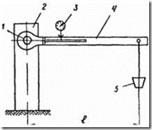
1 - welded hexagon or tightened high-strength bolt;
2 - rigid support; 3 - indicator; 4 - calibrated key; 5 - calibrated cargo
High Strength Bolt Tensioning Methods
1. Tensioning of high strength bolts by torque
1.1. The tension of high-strength bolts to the design force should be done by tightening the nuts with a torque wrench to the calculated value of the torque. Torque value M h required for tensioning high-strength bolts is determined by the formula:
M h = kPd,
k- the average value of the tightening factor for each batch of bolts according to the certificate or set using control devices at the installation site;
R- bolt tension force specified in the KM and KMD drawings;
d is the nominal diameter of the bolt.
1.2. To pre-tighten the nuts, use the pneumatic or electric nutrunners specified in recommended Appendix 4 and torque wrenches.
1.3. When tightening the bolt, the head or nut should be kept from turning with a mounting wrench. If turning does not stop as the bolt is tightened, the bolt and nut must be replaced.
1.4. The twisting moment should be recorded during the movement of the key in the direction that increases the tension.
Tightening should be done smoothly, without jerks.
1.5. Torque wrenches must be numbered and calibrated. They should be calibrated at the beginning of the shift.
2. Tensioning of high-strength bolts according to the angle of rotation of the nut
2.1. High-strength bolts must be installed in holes free from assembly plugs and tightened with a wrench adjusted to a torque of 800 N × m. Each bolt must be tightened until the nut stops rotating. After removing the assembly plugs and replacing them with bolts, the latter must be tightened to a tightening torque of 800 N × m.
2.2. To control the angle of rotation of the nuts, it is necessary to mark them and the protruding ends of the bolts with a combined center punch (see drawing) or paint.
Combined center punch

1 - center punch; 2 - nut; 3 - high-strength bolt; 4 - package
2.3. The final tightening is carried out with a wrench adjusted to a tightening torque of 1600 N × m, while the nut must turn through the angle indicated in the table.
3. Calibration of wrenches according to the angle of rotation of the nut
3.1. Nut runners should be calibrated on a special calibration package consisting of three bodies with at least 20 holes.
High-strength bolts are inserted into the holes of the calibration package and tightened with a wrench until the nut stops rotating. A group of bolts (calibration bolts) in the amount of at least 5 pcs. do not tighten.
The calibration bolts must be hand-tightened with an assembly wrench with a handle length of 0.3 m to failure (initial position).
3.2. On the prepared calibration bolts, the wrench is calibrated.
3.3. The compressed air pressure is set so that when the nut is turned through an angle of 180 ± 30 ° from its original position, the wrench will fail.
The air pressure must be checked periodically.
Air pressure control should be carried out according to the GOST 2405-72 pressure gauge installed at the point where the wrench hose is connected to the line.
3.4. When calibrating a wrench (to monitor the angle of rotation of the nut), marks must be applied to its replaceable head.
3.5. The impact wrench is considered calibrated if the angle of rotation of the nut in the process of tightening all the bolts at the moment of failure of the impact wrench is 180 ± 30°.
3.6. The results of the wrench calibration must be recorded in the wrench calibration log (see mandatory appendix 8).
3.7. In the event of a change in compressed air pressure after the repair of the defect in the wrench, it is necessary to perform a control calibration.
APPENDIX 3
Fire cleaning post equipment
|
equipment identification |
Brief technical characteristics |
|
Burner GAO-60, GAO-2-72 GOST 17357-71 (1 pc.) |
Wide-cut, multi-flame, 100 mm wide. |
|
Oxygen cylinders (3 pcs.) |
|
|
Acetylene cylinders (2 pcs.) |
|
|
Reducer balloon oxygen DKD15-65 or RKD-15-81 |
The maximum overpressure at the inlet is 1962 × 10 4 Pa; operating overpressure - 78.48 × 10 4 Pa; throughput at maximum pressure - 23 m 3 / h |
|
Reducer balloon acetylene RD-2AM, DAP-1-65 |
The maximum overpressure at the inlet is 245.25 × 10 4 Pa; operating overpressure - from 0.981 × 10 4 Pa to 14.715 × 10 4 Pa; throughput - 5 m 3 / h |
|
Rubber sleeves for oxygen supply (GOST 9356-75) with an inner diameter of 9.0, an outer diameter of 18 mm |
Operating overpressure 147.15 × 10 4 Pa |
APPENDIX 4
Equipment, mechanisms and tools used for processing contact surfaces, connected elements and tensioning high-strength bolts
The vibration levels of electric and pneumatic hand grinders and wrenches (Table 1) do not exceed those established in GOST 16519-79 (ST SEV 716-77) and GOST 12.1.012-78.
Table 1
|
Name |
Brand, standard |
Purpose |
|
Electric impact wrenches |
For tightening high-strength bolts during installation and assembly work |
|
|
Pneumatic impact wrenches |
GOST 15150-69 GOST 10210-74 |
|
|
wrenches |
For pre-assembly connections |
|
|
Electric hand grinders |
For cleaning work |
|
|
Electric Angle Grinders |
||
|
Pneumatic hand grinders |
For cleaning metal surfaces from rust and scale |
|
|
Gas burners |
GOST 17357-71 |
For processing contact surfaces |
Noise levels of electric and pneumatic hand grinders and wrenches do not exceed those specified in GOST 12.1.003-76. Vibration parameters and noise characteristics of electric and pneumatic hand-held machines used in processing the contact surfaces of the elements to be connected and for tensioning high-strength bolts are given in Table 1, respectively. 2 and 3.
table 2
Vibration parameters
|
Logarithmic levels of vibration velocity values, dB |
||||||||
Table 3
Noise characteristics
|
Geometric mean frequencies of octane bands, Hz |
||||||||
|
Sound power level, dB |
||||||||
The composition of the adhesive friction coating
|
Name |
Cooking method |
|
|
Epoxy-polyamide adhesive |
Epoxy resin ED-20 according to GOST 10587-76 (100 wt. h) |
AT epoxy resin introduce hardener and accelerator; the resulting mixture is thoroughly mixed |
|
Hardener I-5M (I-6M) acc. |
||
|
abrasive material |
Carborundum powder grade KZ or KCh |
|
|
Solvent |
Acetone according to GOST 2768-79 |
Documents on standardization
Metal structures
« TsNIIPSK them. Melnikov
NIPI "Promstalkonstruktiya"
ORGANIZATION STANDARD
Steel building structures
BOLT CONNECTIONS
Product range and applications
STO-0031-2004
(02494680, 01408401)
Moscow
2004
Foreword
1 DEVELOPED CJSC Central Order of the Red Banner of Labor Research and Design Institute of Building Metal Structures. Melnikova (CJSC "TsNIIPSK named after Melnikov")
OJSC Research and Design Institute "Promstalkonstruktsiya"
2 INTRODUCED by organizations - developers of the Standard
3 ADOPTED at the Scientific and Technical Council TsNIIPSK them. Melnikov dated April 1, 2004 with the participation of representatives of the organization - the developer of the Standard
4 INTRODUCED for the first time
5 The development, approval, approval, publication (replication), updating (change or revision) and cancellation of this standard is carried out by the developing organizations
Introduction
This standard was developed in accordance with the Federal Law "On Technical Regulation" No. 184-FZ and is intended for use by all divisions of ZAO TsNIIPSK im. Melnikov" and OJSC "NIIpromstalkonstruktsiya", specializing in the development of projects of KM and KMD, diagnostics, repair and reconstruction of industrial buildings and structures for various purposes.
The standard can be applied by other organizations if these organizations have certificates of conformity issued by the Certification Bodies in the voluntary certification system created by the organizations - developers of the standard.
Organizations - developers do not bear any responsibility for the use of this standard by organizations that do not have certificates of conformity.
The need to develop a standard is dictated by the fact that the experience gained by organizations - developers of the standard, as well as domestic enterprises and organizations in the field of design, manufacture and implementation of metal structures with bolted field connections, is contained in various regulatory documents, recommendations, departmental rules and others, in part outdated and not covering the whole problem safe operation industrial buildings and structures for various purposes.
The main purpose of developing the standard is to create a modern regulatory framework for the design, calculation, manufacture and implementation of metal structures with bolted field connections.
STANDARDORGANIZATIONS
Approved and put into effect:
Introduction date 2004-04-15
1 area of use
This standard applies to the design, manufacture and manufacture of metal structures with bolted mounting joints, including high-strength ones, designed for load-bearing and enclosing structures of buildings and structures for various purposes, perceiving permanent, temporary and special loads in climatic regions with design temperatures up to -65 °С and seismicity up to 9 points, operated both in slightly aggressive and medium aggressive and aggressive environments with the use of protective metal coatings.
2 Normative references
This standard uses references to the following normative documents:
GOST 7798-70 Hexagon head bolts of accuracy class B. Design and dimensions
GOST 7805-70 Hexagon head bolts of accuracy class A. Design and dimensions
GOST 1759.4-87 Bolts, screws and studs. Mechanical properties and test methods
GOST 1759.5-87 Nuts. Mechanical properties and test methods
GOST 5915-70 Hexagon nuts of accuracy class B. Design and dimensions
GOST 5927-70 Hexagon nuts of accuracy class A. Design and dimensions
GOST 11371-78 Washers. Specifications
GOST 22353-77 High-strength bolts of accuracy class B. Design and dimensions
GOST 22354-77 High-strength nuts of accuracy class B. Design and dimensions
GOST 22355-77 Accuracy class C washers for high-strength bolts
GOST 22356-77 High-strength bolts and nuts and washers. General specifications
GOST 24379.0 Foundation bolts. General specifications
GOST 24379.1 Foundation bolts. Design and dimensions
SNiP II-23-81* Steel structures. Design standards
Manual for the design of steel structures (to SNiP II-23-81*)
SNiP 2.03.11-85 Corrosion protection of building structures
GOST 1759.0-87 Bolts, screws, studs and nuts. Specifications
GOST R 51163-98 Thermal diffusion zinc coatings on fasteners and other small items. General requirements and control methods
3 Assortment of fasteners
3.1 For connections of building metal structures, bolts with a hexagonal head of normal accuracy according to GOST 7798 or higher accuracy GOST 7805 with a coarse thread pitch of diameters from 12 to 48 mm, strength classes 5.6, 5.8, 8.8 and 10.9 according to GOST 1759.4 . hex nuts normal accuracy according to GOST 5915 or higher accuracy GOST 5927 strength classes 5, 8 and 10 according to GOST 1759.5 , round washers to them GOST 11371 execution of the 1st accuracy class A, as well as high-strength bolts, nuts and washers according to GOST 22353 - GOST 22356 diameters 16, 20, 22, 24, 27, 30, 36, 42 and 48 mm.
3.2 Bolts having sections with different diameters along the length of the uncut part (up to the average diameter) are not allowed to be used in joints in which these bolts work in shear.
3.3 The designation of the bolt strength class consists of two digits - the first corresponds to 1/100 of the nominal value of the tensile strength in N / mm 2, the second 1/10 of the ratio of the nominal value of the yield strength to the tensile strength in percent. The product of these two figures corresponds to 1/10 of the nominal value of the yield strength in N/mm 2 .
3.4 Strength class of a nut with a nominal height equal to or greater than 0.8d(where d- nominal thread diameter) is indicated by a number indicating the highest bolt strength class with which they can be mated in a connection.
3.5 Marking of bolts and nuts is obligatory indicating the manufacturer and the strength class of the product.
3.6 Bolts, nuts and washers intended for various types of connections must meet the requirements specified in the table .
Table 1
|
Bolt strength classes |
Nominal bolt diameters, mm |
Bolt steel grades |
Designation of state standards |
Difference of nominal diameters of holes and bolts, mm |
|||
|
bolt |
screw |
washer |
|||||
|
Friction |
high-strength |
16, 20, 22, 24, 27 |
40X "Select" |
GOST 22353 |
GOST 22354 |
GOST 22355 |
1 - 6 |
|
10.9 |
12, 16, 20, 24 |
40X, 20G2R |
GOST 1759.4 |
GOST 1759.5 |
GOST 22355 |
1 - 3 |
|
|
Friction shear and shear |
high-strength |
16, 20, 22, 24, 27 |
40X "Select" |
GOST 22353 |
GOST 22354 |
GOST 22355 |
0,3 - 3 |
|
10.9 |
12, 16, 20, 24, 27 |
40X, 20G2R |
GOST 1759.4 |
GOST 1759.5 |
GOST 11371 |
||
|
35, 35X |
|||||||
|
20, 30, 35 |
|||||||
|
10, 20 |
|||||||
|
Flanged |
high-strength |
20, 24, 27 |
40X "Select" |
GOST 22353 |
GOST 22354 |
GOST 22355 |
1 - 4 |
3.6 The design, dimensions and steel grades for foundation bolts should be taken according to GOST 24379.0 and GOST 24379.1.
3.7 Nuts for foundation bolts made of steel grades Vst3sp2 and 20 with a diameter of less than 48 mm should be used according to GOST 5915 strength class 4, for foundation bolts made of steel grades 09G2S and 10G2S1, strength class at least 5 according to GOST 1759.5 . For bolts with a diameter over 48 mm - according to GOST 10605.
3.8 For flange connections of antenna-mast structures, it is allowed to use high-strength bolts made of steel grade 30KhZMF with a diameter of 30, 36, 42 and 48 mm according to GOST 22353, nuts according to GOST 22354 and washers according to GOST 22355.
3.9 Bolts of strength class 10.9 for friction and bolts of strength classes 10.9, 8.8 for friction-shear connections can be used with nuts according to GOST 22354 and washers according to GOST 22355 . The strength class of nuts must not be lower than the strength class of bolts.
4 Types of connections and conditions for their use
4.1 This standard applies to building metal structures of industrial buildings and structures for various purposes with bolted mounting connections.
4.2 The standard provides for the use of the following types of bolted connections:
Friction (shear-resistant) joints, in which external forces are perceived exclusively by friction forces arising along the contacting planes of the elements to be joined after the bolts are tensioned by the calculated axial force;
Friction-shear connections, in which external forces are perceived by the resistance of the bolts to shear, and the connected elements - to crushing, taking into account the friction forces that arise along the contacting planes after the bolts are tensioned by the calculated axial force;
Shear connections, in which external forces are perceived by the resistance of the bolts to shear, the connected elements - to crushing;
Flange connections;
Foundation connections in which external forces are taken up by the tensile strength of the bolts.
4.3 When designing steel structures and their elements, as a rule, bolted mounting connections should be provided; welded field connections are allowed with appropriate justification.
4.4 For structural elements with bolted connections, rolled steel should be used in accordance with Appendix 1 SNiP II-23-81*, edition 1991
4.5 Steel building construction industrial buildings and structures with bolted mounting connections, depending on the degree of responsibility and the conditions of their operation, are divided into three groups:
Group 1.Structures and their elements operating in particularly difficult conditions or directly exposed to alternating, dynamic, vibration or moving loads, including structures designed for endurance (crane beams); crane-under-rafter trusses; floor beams of technological and working platforms; joints of beams among themselves; brake structures; nodes of horizontal and vertical connections along the belts of roof trusses; joints of stretched belts of rafter and truss trusses on overlays; farm cuts; attachment points for vertical ties along columns; structural elements of bunker and unloading racks that directly perceive the load from rolling stock; span structures, supports of transport galleries, etc.
Group 2Structures or their elements operating under static load - floor beams of technological and working sites; farms; frame crossbars; beam joints; belts of truss and truss trusses on overlays; attachment points for horizontal and vertical ties along the belts of truss trusses for buildings with light and medium duty cranes; attachment points for overhead transport and monorails; attachment points crane rails; split crane beams between themselves and to the columns; attachment points of truss trusses to columns and truss trusses; truss trusses to the columns, subject to the transfer of vertical support pressure through the table; stringers of stairs, etc.
Group 3.Auxiliary structures of buildings and structures - ties, half-timbered elements, stairs, ladders, platforms, fences, etc.
4.6 Friction (shear-resistant) connections should be used in structures and their elements for which residual shear movements are not allowed (group 1).
4.7 Friction shear joints should be used in structures and their elements made of steel with a yield strength of up to 380 MPa (3900 kgf / cm 2), operating under static load, as well as under the influence of alternating forces, when the smaller of them can only be transferred by forces friction (groups 1, 2 and 3).
4.8 Shear joints should be used in structures and their elements made of steel with a yield strength of up to 380 MPa (3900 kgf / cm 2), operating under static load, as well as in auxiliary structures of buildings and structures for various purposes (groups 2 and 3).
4.9 Flange connections should be used in structures and their elements subject to tension, compression, tension with bending, local transverse forces, including moving, vibration or other types of loads with a number of loading cycles n up to 10 5 and voltage asymmetry factorr ≥ 0,8.
5 Applications for connections
5.1 Depending on the climatic region of the construction of metal structures of an industrial building or structure under construction, their operating conditions (calculated or not calculated for endurance), bolt operating conditions (for shear or tension), bolt strength classes should be assigned according to the table .
table 2
|
Design temperature of the climatic area of construction, °C |
bolt conditions |
Bolt strength class |
Bolt steel grade |
Bolt Requirements |
|
In structures not designed for endurance |
||||
|
t ≥ - 40 |
stretch or shear |
20, 30, 35 |
According to GOST 1759.4 |
|
|
10, 20 |
||||
|
35, 35X |
||||
|
10.9 |
40X, 20G2R |
|||
|
high-strength |
40X "Select" |
According to GOST 22353 |
||
|
40 > t ≥ -65 |
stretching |
20, 30, 35 |
According to GOST 1759.4 with guaranteed impact strength |
|
|
35, 35X |
||||
|
10.9 |
40X, 20G2R |
|||
|
high-strength |
40X "Select" |
According to GOST 22353, version HL |
||
|
slice |
20, 30, 35 |
According to GOST 1759.4 |
||
|
10, 20 |
According to GOST 1759.4 with additional leave t = 650 °С |
|||
|
35, 35X |
According to GOST 1759.4 with guaranteed impact strength |
|||
|
10.9 |
40X, 20G2R |
|||
|
high-strength |
40X "Select" |
According to GOST 22353, version HL |
||
|
In structures designed for endurance |
||||
|
t ≥ -40 |
stretching |
20, 30, 35 |
According to GOST 1759.4 with guaranteed impact strength |
|
|
35, 35X GOST 1759.4 GOST 22353 |
||||
|
high-strength |
40X "Select" |
According to GOST 22353, version HL |
||
5.2 Bolts, nuts and washers with protective metal coatings should be used for connections:
Structural elements with protective metal coatings applied by hot or thermal spraying (zinc or aluminum coatings);
Structural elements made of aluminum alloys;
Elements of antenna structures, masts and supports of power transmission lines;
Structures operated in a medium aggressive environment according to the classification of SNiP 2.03.11 Table. 13, together with paint coatings;
Elements of railway, urban and surface bridges, gas pipelines;
Structural elements calculated for endurance;
Flanged and bolted connections calculated for tension;
Particularly responsible structures; swimming pools, water stadiums;
Structural elements operated in marine atmosphere (bolts, nuts and washers with cadmium coating).
5.3 As a protective metal coating for bolts, nuts and washers, as a rule, thermal diffusion coating should be used. GOST R 51163-98 or hot zinc coating using centrifugation and cutting nuts with taps according to customer's request:
In slightly aggressive environments as an independent coating;
In moderately aggressive environments with an additional paint coating applied after assembly of the unit.
5.4 For structures operated in slightly aggressive environments, it is allowed to use bolts, nuts and washers with metal coatings according to GOST 1759.0 tab. 5 with digital symbols - zinc, chromated (01), cadmium, chromated (02), zinc (09) with an additional paint and varnish coating.
5.5 For structures operated in aggressive environments, bolts, nuts and washers made of corrosion-resistant, heat-resistant, heat-resistant and heat-resistant steels according to
Keywords:fasteners, strength class, connection, shear, shear, crush, tension, friction, force, twisting moment