Automatic drilling machine with illumination scheme. Drill for printed circuit boards. Features of equipment for drilling holes in printed circuit boards
With the invention of machine tools, mankind has seriously advanced in the field of production various kinds details and mechanisms. Machine tools have become a real help for anyone who intends to process metals, wood and any other materials.
After all, these devices are originally intended to perform rather specific work, which you will not be able to perform in a different way.
Homemade machine for printed circuit boards from a guide rail
Such equipment also includes a drilling machine for printed circuit boards, which is used in electromechanics and related production areas.
1 General information
Any machine is special device, which is assembled from several components. The task of this device is to give a person the opportunity to process a particular tool with great accuracy. That is, practically exclude manual labor from the process.
This is absolutely necessary in work where accuracy is needed. If a part made of metal or any precise material, then you simply cannot do without the use of a machine.
See also: about the purpose and types of collets.
The machine consists of a frame, adapters, installation under the engine and several other mechanisms. All of them are assembled into a single structure, which is rigidly fixed in one or more positions.
Standard and cheapest machines or mini-machines if we are talking about equipment that designed for processing miniature parts, can only move in one axis. That is, the movement of the working drill is performed from top to bottom. This is the basic function of the machine, without which it cannot be called a machine.

Pneumatic Mining Drill for Machine Tool
More advanced models can be fine-tuned to a specific coordinate that is displayed on the table. It can already be even semi-automatic or automatic models.
As you understand, it is precisely the clear fixation on a solid frame and the ability to practically eliminate the human factor directly in the performance of drilling work - this is the main plus of the machines.
1.1 Features of PCB machines
Machines for printed circuit boards - this is one of the varieties of such equipment. Here are just such units, as a rule, are mini-samples. And this is quite obvious, because it is necessary to work on them with printed circuit boards.
For those who are not familiar with electrical engineering, let's be clear that printed circuit boards are essentially the basis for any microcircuit or electronic mini-circuit. Almost every device in its design has at least one printed circuit board. This is especially true for appliances that run on electricity.
To form uniform standards in electrical engineering and create a stable foundation, printed circuit boards were introduced. They are made from a dielectric, on which various parts and connections are screwed or soldered.
The board can contain both a small transistor and a lead to it from the battery, as well as a huge number of parts, so miniature that an unprepared person will not even consider them(we are talking about computer hardware).
Of course, in this situation, it is worth noting the huge number of printed circuit boards that differ in their design, material used, etc. But we note that all of them are a kind of one element, which acts as the basis for microcircuits.
The simplest boards equip additional elements due to their screwing and subsequent soldering. As you understand, for screwing parts, you need to make holes in the board.
Read also: about TV machines and their purpose.
And it is necessary to do them with filigree precision. A discrepancy of even half a millimeter can be, if not fatal, then very noticeable. Especially if you are going to fill the board completely.
Installing the drill on the machine
What is the fact that drills for a mini-machine on printed circuit boards in their diameter can start from samples of 0.2-0.4 mm. And this is if we talk about cheap machines. More advanced hardware to build complex circuits will use even smaller tools.
As you understand, to process similar details manually is no easy task. Even if you manage to make a couple of holes in the right place and the right thickness, this process will take too long, and the result can be spoiled by a single mistake.
Using the same machine for printed circuit boards, work is greatly simplified and becomes almost mechanical. As well as increasing its performance. And the design of such equipment does not differ in complexity, so you can create it yourself.
to the menu
2 Machine design
The design of mini PCB processing machine has quite a simple circuit. In fact, this machine is not much different from standard drilling models, only it is much smaller and has several nuances. We almost always consider a desktop mini drilling unit, as it will have dimensions that rarely exceed the 30 cm mark.
If we consider a home-made sample, then it may be a little larger, but only due to the fact that the person who assembled it with his own hands simply could not optimize the design properly. This happens if there are simply no suitable parts at hand.
In any case, the machine, even if it is assembled by hand, will have small dimensions and weigh up to 5 kilograms.
Let us now describe directly the design of the machine, as well as the parts from which it must be made. The following are used as the main components when assembling a mini-device for drilling boards:
- bed;
- transitional stabilizing frame;
- bar for moving;
- shock absorber;
- a handle for manipulating height;
- engine mount;
- engine;
- power unit;
- collets and adapters.

It looks like a finished homemade drilling machine for printed circuit boards
So, the list of equipment used is quite voluminous, but in fact there is nothing complicated here.
2.1 Analysis of specific details
Let's turn now to specific details that have already been mentioned above, and we will also give recommendations on their selection.
To begin with, we note that we are now describing a home-made machine, which, in fact, can be assembled from improvised means. The design of factory samples differs from that described by us only in the use of specialized materials and details that are almost impossible to create at home. Will have to buy.
A home-made mini-machine begins, like any other machine, from the bed. The bed acts as a base, the entire structure rests on it, and a supporting part is mounted on it, on which the processed board is attached.
It is desirable to make the bed from a heavy metal frame. Its weight should be greater than the weight of the rest of the structure. Moreover, the discrepancy can be quite impressive. The only way you will achieve the stability of the unit during operation. This is especially true for models that are assembled by hand.
And do not be deceived when you see the mini prefix. A mini-machine is the same machine, and it still requires high-quality stabilization. Legs or something similar are often screwed under the bed to further fix its position.

Homemade drilling machine with a stabilization frame
The stabilizing frame is the mount for the entire mechanism. It is made from a rail, a corner or something like that. It is preferable to use detail. The bar for moving can be the most various designs and is often combined with a shock absorber. Sometimes, the shock absorber itself is a bar for movement.
These two parts perform the functions of vertical displacement of the machine during operation. Thanks to them, the machine can be operated quickly and effortlessly.
There are a lot of options for making such details. Ranging from homemade or taken from office furniture sliding rails on a spring, to professional oil-type shock absorbers.
The handle for manipulation is attached directly to the machine body, shock absorber or stabilizing rail. With its help, you can apply pressure on the structure, lowering and raising it at will.
A bar for the engine is already attached to the stabilizing frame. It may even be ordinary wooden block. Its task is to bring the engine to the desired distance and its secure fixation.
The engine is mounted on a mount. Can also be used as an engine huge amount details. Starting from a drill, and ending with engines that are removed from printers, disk drives and other office equipment.

Drills for drilling holes in printed circuit boards
Collets and adapters are attached to the engine, which will be the basis for attaching the drill. Here you can only give general recommendations, as adapters are always selected individually. Their choice will be influenced by the motor shaft, its power, the type of drill used, etc.
The power supply for the mini-machine is selected so that it can provide the engine the right voltage in sufficient quantities.
2.2 Machine assembly technology
Now let's turn to general algorithm, according to which the unit for drilling printed circuit boards with their own hands is being assembled.
- We mount the frame, attach the legs to it.
- We install the frame of the holder of the main structure on the frame.
- We fasten the movement mechanism and shock absorber to the frame.
- We mount the mount for the engine, as a rule, it is fixed on the movement frame.
- Install the handle on the engine mount.
- We install the engine and adjust its position.
- We fasten the collet and adapters to it.
- We mount the power supply, connect it to the engine and the network.
- We select and fix the drill.
- Testing the mechanism.
All connections and their type you can choose at your discretion. However, it is recommended to use bolts and nuts in order to be able to disassemble the structure at the right time, replace its components or improve the entire scheme of the machine.
to the menu
2.3 Homemade machine for drilling printed circuit boards (video)
Do-it-yourself drilling machine for printed circuit boards.

Almost a year ago, I finally assembled a machine for drilling printed circuit boards. Until then, like many others, I used a small engine with a cartridge mounted on the shaft.
One day I got tired of all this, and I decided to design something of my own. At first I thought to design something of my own design, since I already picked up something for the feed mechanism and shoveled the Internet in search of suitable structures for repetition.
I must say that there are still designs worthy of attention, and made beautifully and competently. But there are also such as if made with an ax.
But then, at a flea market, I came across a skeleton from a microscope in a very deplorable state. I can't imagine how people from science could bring him to such a state.
Bargained for ten euros. Already at work, I went through all this stuff, washed it, restored the mechanics and removed all the backlash. Further, I removed the inclined console and instead made a horizontal one from D16T. I made the motor mount from the same material. Now the design turned out to be more compact in height, and outwardly acquired the outlines of a machine. The fastening of parts to the frame was done with the help of pins and bolts.
I'm going to digress a bit and talk about myself. I work in a car service, so in my design I used everything that lay under my feet and could find a use. Of the equipment, I mainly used desktop drilling machine semi-artel production. All operations such as: drilling and milling, grinding and some turning, I did on it. From the tool I used files, needle files, drills, reamers, taps, a hacksaw and much more, I can’t list everything. In general, it took me a couple of months to complete all this (everything was done in my spare time). Everything turned out great, but disappointment came after the first inclusion. The reason was the vibration created by the cartridge.
It so happened that once upon a time I fell into the hands of a jammed Opelevsky fuel pump. And poraskinuv a little brains, I converted it into a drill. The characteristics of this engine are quite solid. Once I tried to drill steel with it using a ∅6mm drill.
I should note that not every electric fuel pump can be suitable for these purposes. I have a lot of this good lying around, and I once "anatomized" a dozen different models. There are quite a lot of different unpleasant moments associated with the design of the electric motor itself. Although, with a great desire and skill, I think you can do anything.

When you hold the engine in your hand and drill, then small flaws such as vibration and eccentricity are almost not noticeable. In the machine, everything is different. And then I began to look for another cartridge for my engine. This cartridge had a threaded fit on the shaft, and making a new adapter for it would be a waste of time. Collet option did not even want to consider. In my opinion, the chuck is a universal tool, and the collet provides for drills of certain sizes. A little diameter is not the same and the drill is either not inserted or describes circles.
And I found what I was looking for from a tool dealer. The cartridge turned out to be made in the Celestial Empire, but it looks surprisingly quite cultured, the workmanship is simply excellent. And in terms of money, only 8 European rubles is not so expensive, translated into our Moldovan lei.

Here is the data on the cartridge
Dimensions:
- outer diameter - 21.5mm
- larger cone diameter - 6.350 mm
- smaller cone diameter - 5.802 mm
- cone length 14.5 mm
- ellipse 0.02 mm
Cone: JT0 (2 degrees 49 minutes 24.7 seconds)
Drill diameter: 0.3mm - 4mm
Weight: 73.3g
And, even the seller of the cartridge promised to help with the adapter for the cartridge. But time passed, and there was still no adapter. About six months later, without waiting for the coveted adapter, I decided to turn to familiar turners. But even there I was disappointed. In principle, I did not have high hopes in this regard, because I knew that you could not get great accuracy on machines manufactured in the 70s and 80s. Then I decided to try to make a cone on my own. It would seem that the task is impossible, but as they say, everything ingenious is simple. I noticed one auto detail. It is a nozzle from the mechanical fuel injection of gasoline cars of the 80s, 90s manufactured by BOSCH.


In the first photo: nozzles (injectors) in version 1 - made of steel, 2 - made of brass, 3 - cut and drilled workpiece, 4 - finished workpiece, 5 - workpiece mounted on the axis.
What attracted me to this detail? And above all, the fact that it has a ready-made through hole. Secondly, it is made with very high precision. This is the so-called precision mechanics. Thirdly, I have gathered quite a few of this goodness that has fallen into disrepair. So there was a lot to experiment with. In the end, after some experimentation, we managed to get what we wanted.
As I said, I only have a desktop drilling machine at my disposal. This is where I made my pieces. Drilling holes did several in an unusual way, that is, the workpiece itself was clamped in the machine chuck, and the drill in special device made of two metal bars with holes of different diameters drilled in the center (see figure).

You can also use a tap holder. When drilling, it is advisable to use new drills and the drill overhang should be as short as possible. Then the probability of deviation from the center will be minimal. Under the protruding lower part of the drill, you can put any object with parallel planes and having through holes. Suitable for any bushings, bearings, chipboard or MDF.
Initially, a hole is drilled for the diameter of the motor shaft. In this case, the diameter of the motor shaft of my machine is 6 mm. The drill diameter is taken 0.1 mm less, i.e. 5.9 mm. Next, a through hole is drilled for the M 4 thread. The thread is needed in order to be able to extrude the workpiece from the shaft if necessary. It is advisable to make several pieces of blanks, since the beating of the blank on the shaft, or the deviation of the hole from the center, is not excluded.
When manufacturing a workpiece from a calibrated bar, at the beginning, after preliminary marking, you must first make a call center drill. If it is possible to make a preparation for lathe, then the task becomes much simpler. But this is only the first stage. Next, you need to slightly heat the workpiece and put it effortlessly on the motor shaft. After cooling, the workpiece is held on the shaft very firmly without any additional screws. This is the so-called hot landing. After that, I checked the workpiece for runout and center deviation. I was satisfied with the second one made. The surfaces of the mating parts should not have traces of lubrication, since when heated, the lubricant burns out, and the mating parts seem to stick together. In the future, if necessary, it will be very difficult to separate them.
Somehow, after talking with my friend from the student bench, the idea of further continuation of the idea appeared. After sitting at the computer for a couple of hours, I modeled a device for grinding a cone. It took a couple more hours to make this rig. And the manufacture, that is, grinding the cone, takes about forty minutes. And then with breaks for measurements. You will laugh, but I did all this in my kitchen, fixing this whole structure with two clamps on a stool.
In general, the result exceeded all my expectations, while the machine is working, the drill seems to stand still. If earlier, each time you drilled holes, you had to stop the engine to get to the future center of the hole, but now you can drill without stopping and without the risk of breaking the carbide drill.
Whether anyone has done something like this before me or not, I don't know. At least I haven't found anything like it anywhere. The fact is that it is still possible to achieve sufficiently high accuracy in artisanal conditions without resorting to the help of a machine operator. True, if the arms and head grow from the shoulders.
The model of this device looks like this.


Appearance devices front and rear.

Processed cone (enlarged).

For grinding, it is desirable to use a new stone, and the rotation of the part and the stone should be mutually opposite.
By rotating the screws A, A1 and B, B1, we feed the part. By loosening screw B1 and screwing in screw A1, we give the part a taper. Guides, (pos. 1) made from scraps square pipe section 15 × 15, thrust plates (pos. 2 and 3) steel, 5 mm thick. Bolts (pos. 6) fasten the thrust plate to the fixed plate (pos. 5). The plate (pos. 2) is attached to the movable plate (pos. 4). Guide grooves in the movable plate (pos. 7). It is very convenient to use hexagon head bolts as fasteners, especially the feed bolts pos. A, A1 and B, B1. By turning them with a hexagon, the feed is very easily controlled. It is advisable to leave a gap of about 1mm per side between the guides and the movable plate. The plate itself should move in the longitudinal direction quite tightly, with a slight creak. The bolts (pos. 7) achieve the necessary adjustment. The material for the manufacture of the grinding device can be chipboard, MDF, thick plywood or sanded wood. hard rock. I used 22mm MDF.
At various materials There are certain disadvantages that need to be taken into account. So MDF boards tend to delaminate in the longitudinal direction when bolts are screwed in. The wood is prone to splitting.
Now a few words about the design of the machine.
The engine was mounted in the frame according to classical scheme. Similar from the site ydoma.info/samodelki-mini-sverlilnyj-stanok.html?cat=5.
This option provides a very reliable and rigid connection of the engine with the structure.

I combined the backlight together with a magnifying glass, it turned out very convenient in my opinion. The light is always directed from the eyes towards the instrument.


I made a flexible sleeve again from what it was, took aluminum balls ∅ 9 mm from the triggered seat belts and connected them in pairs copper tube. I connected them together with short pieces of a tube made of a plastic gas pipeline with an inner diameter of 8 mm. After preheating the ball mounted on a steel rod, the tube is mounted on the ball until a hemisphere is formed on the tube. It's that simple. How this joint looks like is shown in the figure.


The lifting and lowering wheel was machined from ebonite ∅ 50 mm and tightly planted on the regular one. Management has become much more convenient than before.
Adding an additional lever was not considered necessary.
The feed of the tool during drilling is already very easy and smooth.

I didn’t bother much with the power supply (I think that what easier themes more reliable), made it based on a 100 watt torus with a simple rectifier. Although there was an idea to make an impulse switch, since there is a good recommended scheme. 10-position speed selector switch. The supply voltage is from 4 to 14 V. The case was taken from a 3.5″ floppy drive (for sure no one else uses this stuff). True, it has been slightly altered.
The control of turning on the engine by means of a pedal does not occupy the hands when drilling boards.
Well, at the end of the car, the painter painted all the details separately.
Around the run, I spent about 40 euros on all this, and in general I think that it is not very expensive for such a pleasure.
Somehow like this.
Once upon a time in the early 80s, I had a drill for p / boards based on the GDR - an electric motor and a small chuck from a drill on a 1st Morse taper.
The motor type was not preserved, but the diagram was copied into a notebook.
In those years, there were no home computers, and that's all. interesting schemes and brain research was entered into common notebooks in a box, 96 sheets each, worth 44 kopecks.


The scheme worked according to the algorithm: a small load - the cartridge rotates slowly, the load increases - the cartridge rotates faster. It was very convenient to use it for drilling holes in p / boards, I got into punching - the speed increased.
Many years have passed, the drill has long since sunk into oblivion. Recently I was puzzled by the problem of drilling holes in p / boards. Due to the lack of such transistors (especially P-701), I had to translate the circuit to modern details:


P / board is universal: there is a KT972 - we put it and a jumper from the base into the emitter of a small transistor, there is no KT972 - we put KT315 and an analogue of KT805, as in the photo.
Another scheme has developed in the head of another author: Edward Nedeliaev (http://www.cqham.ru/smartdrill.htm). I came across this link after a week of unsuccessful attempts to make the circuit work with a PDM type motor. Although, as we know from the classics, what one homo sapiens has collected, another homo sapiens will always be able to disassemble. As it turned out, the scheme does not work with DPM motors, you see, only the DPR series engines should be supplied to it.

But there is no DPR motor and there is no desire to buy it, but there is such a box and a pick from it.

Starts from this place laboratory work on the topic "Choose the control of the PICKER for P / BOARDS." The Internet is full of different schemes, simple and not very easy to control drill motors for p / boards. Let's look at some of the most common ones:
1. regulator on transistors without the use of microcircuits (the K142EN series is ignored)
2. regulator on transistors and microcircuits.
3. regulator on transistors and a microcontroller.
4. voltage regulator (let's skip it, it is of little interest for use in the purposes and tasks under consideration)
First, let's try the scheme of A. Moskvin, Yekaterinburg:


The scheme perfectly fulfills its functions and responsibilities:
1. touch controlled (start/adjust/stop)
2. changes speed
3. slows down the engine
4. almost no settings required
If we use a halved area with the size of 1 penny coin, then the application of a finger is very convenient to turn on and adjust the engine speed.
In the magazine "Radio" for 2009 there was a different scheme for DPM motors. It was invented by S. Saglaev, Moscow. I had to change some ratings for my motor.


The circuit works well enough, but somehow thoughtfully. Maybe it has something to do with the engine I have.
The second for the experiments we take the so-called PWM controllers.
There are a great many variants of schemes and the authors are simply legion. For this reason, the names and surnames of the heroes are not given here.


The circuits work, but are more suitable for controlling the speed of a fan with a collector motor. More acceptable parameters for drilling have schemes on the NE-555 timer:


One of the circuit solutions is the use feedback. The Arsenal forum (http://www.foar.ru) borrowed two such schemes:


These variants of schemes are worthy of attention and repetition. It should be noted that the version with the KD213 diode was honored to be installed in the case, and took an empty place in the gray box along with a picker and drills. Probably simple so-called PWM controllers are most likely suitable for a stationary drill like this one:

The next in line is the microprocessor type of drills. The West, as usual, helped us with a circuit solution: http://mondo-technology.com/dremel.html I made this circuit about three years ago, a dead Dremel acted as a guinea pig. An imported 24 volt motor was installed inside and powered from this circuit:


The construction turned out to be remarkably working, it is still used at work and deserves only commendable reviews. By the way, the holes in the p / boards in the photographs were made by her.
As an option for drilling, a circuit was tested on ATtiny13 (by hardlock, http://www.hardlock.org.ua/mc/tiny/dc_motor_pwm/index.html):


A nice and well-functioning design, but I want to emphasize again that it is more suitable for a stationary drill.
And finally, the design, which conquered with its repeatability and ease of use. The Bulgarian Aleksandar Savov came up with and implemented the scheme back in 1989:


The scheme works fine according to the algorithm stated at the beginning:
1. small load - the chuck does not spin fast.
2. load increases - the chuck spins faster.
The scheme is deeply indifferent to which motors to work with:


All the engines that were available at home were tested under the control of this design and worked out the test perfectly. The results exceeded all expectations. A slight adjustment by the resistor RP1 of the minimum rotor speed you need and by the resistor RP2 - stable, without jerks, rotation, and that's it, the engine is running.
P.S. Do not forget about the power supply, which should not keep your picker on a current starvation.
All questions, as always, in the Forum.
Ghostgkd777 › Blog › PCB Drilling Machine
Hello!
I have been going to this for a long time, finally I got around to it and in 12 hours I made a picker for seals.
I took the kinematics with a moving engine. The pun turned out)) In general, the engine with the cartridge is lowered.
The sled and the “eyes9quot” carriage are taken as the basis of this knot; CD-ROM or any other drive. I mounted the engine on it, springed it to the frame, attached a lever for lowering, fixed this whole structure on an aluminum corner, which, in turn, through a spacer to the base of a fiberglass plate.
A photo of the entire structure is below.
carriage with a corner under the engine
the spring is in place, the tip of the upper position of the carriage is installed
hair dryer engine, quite high-torque
a separate conversation about the collet chuck
The rubbish is still that, I'll tell you ... far from all drills hold well. Working with him brings the sea negative emotions. And to change it to a normal cam chuck - it's too big for this motor. Therefore, this version of the drill is recognized as a temporary solution until the acquisition of a 24V motor and a normal cartridge. There we will build a more impressive pick))
But it would be too easy to stop there! On the motor, I attached a diagram with automatic regulation of the motor speed depending on the load, which I spied on the cats laid out by Sansey. By the way, very good review engine control schematics are there. Recommend!
Dear admins and moderators, do not take it as an advertisement for another resource. The material is interesting, it will come in handy for people, but copying it into your blog is somehow not good.
I went through and adjusted to the details I have.
The tip set to shunt the BE VT2. in the upper position of the carriage, it is closed. He has one contact (from the same hair dryer as the motor), too lazy to look for normal tips))
- City: Rubtsovsk
Homemade drilling machine for printed circuit boards
well, if it went to an exhibition of drills, then I will also participate
So here it is:
A little bit of description: the motor is powered by a 220v / 6v transformer through a rectifier, although according to its performance characteristics it must be powered by 12 volts (such a power source is in search); drills can be used any up to 3mm. Now planted on the motor shaft homemade adapter from 4mm (shaft) to 3mm ( maximum diameter drills), but this is temporary because it takes an extremely long time to change drills (find a suitable bushing, center it.). Ideally, he needs collet on a 4mm shaft. Now I use a 1mm drill.
The next two photos show my jambs. Unfortunately, I could not achieve parallelism between the axis of the rack and the axis of the shaft. But surprisingly, this does not interfere with drilling in any way (checked repeatedly):
But this detail is special, because he himself poured out of duralumin
I did not make any levers for raising and lowering the drill. I control the machines like this:
I like it, it's convenient.
And here is the textolite that was tested on the first day of operation of the machine:
- Moscow city
- Name: Maxim Braterskiy
Homemade drilling machine for printed circuit boards
ten years ago I bought a coordinate table in Mitino 100 by 100 mm DSHI200-1 engines.
"cnc9 assembled from a computer 386sx. the program issued on LPT 8 bit 4 per engine.
each bit drove one transistor. the file for drilling was prepared by PCAD7 ORCAD9.
- Tomsk city
- Name: Dmitry
Homemade drilling machine for printed circuit boards
Very interesting designs, I also recently made myself a machine tool made of wood and a piece of guide from a printer with a carriage. It seems that you can live, but. The feed is organized anyhow, i.e. the engine is spring-loaded and lowers only when you press it. Rigidity is again nil, although it was fastened with corners. Photo in the evening. I’m thinking of making the machine more decent, everything would be fine, but I can’t find a rack and pinion feed mechanism, no microscopes, no unnecessary parts from old technology no. I read somewhere that it's very good. door closer, but it costs a kiloruble and more, so it's not an option. And my machine needs a good reach, because. boards are also 30x30 cm, it comes out 150 mm from the drill to the base of the rack. The base and the rack are not a question, but the feed mechanism, and I don’t know so that it doesn’t wedge.
- Tomsk city
- Name: Dmitry
Homemade drilling machine for printed circuit boards
Here is the photo.
A very modest craft, compared to others.
There is only one consolation - as soon as I finish a large series of boards, I will start building something more decent. A hand drill is not even a match for my monster!
Development of an electronic circuit for controlling electric motors direct current in an optimized CNC machine.
Objective: PCB fabrication optimization using original design CNC drilling machine.
In the manufacture of printed circuit boards in an amateur or educational laboratory, there is a problem of quickly drilling a hole for the legs of parts, according to a pre-designed drawing. wiring diagram. The problem lies in the high frequency and small diameter of the holes (for example, under a microcircuit), which makes it inconvenient and dangerous (there is a possibility of chipping the drill) to carry out the drilling process manually.
During operation, using theoretical method research, we reviewed the devices proposed by other authors to solve this problem. Such devices are all kinds of machines with numerical control, which drill holes on the workpiece according to a pattern previously entered into the control program. We have studied the main distinctive features of these devices and identified their pros and cons. These machines operate under the control of various programs and have quite different structure, but still there is one feature that unites all the proposed designs. This feature is the use of stepper motors in machine tools. Option homemade machine with CNC using stepper motors is shown in the figure:

This reduces the smoothness of the machine, as stepper motors work in jerks. Also, the use of stepper motors increases the cost of the machine, since the cost of powerful stepper motors starts from 1,500 rubles, and you need to use three of them, or, if motors of lower power are used, put them in two for each axis of movement. But replacing stepper motors with DC motors required a change in control drivers. circuit diagram stepper motor drivers is shown in the figure:

The electronic part of the machine has been changed almost completely.
Using practical method research, we have developed electronic circuit, where the direction of rotation of the electric motors is switched using magnetic relays, and the relays themselves are controlled by transistor switches. A schematic diagram of DC motor control drivers is shown in the figure:

The circuit works as follows: the control program developed during the design of the machine outputs logical levels "0" and "1" to the outputs of the LPT port. The bases of transistor switches VT1 - VT7 are connected to the corresponding pins of the port.
Transistors VT1 and VT2 control the electromagnetic relays K1 and K2, to the contact of which the motor of the transverse feed of the tool in the horizontal plane is connected. By switching electromagnetic relays, the supply voltage (12V) is switched with the contacts of the M1 electric motor. When the relay K1 is turned on, the motor M1 starts to spin to the right, when K2 is turned on, it starts to turn to the left. When both relays are off, the motor is in the rest position, since negative potential is applied to both of its contacts.
The control of longitudinal feed motors in the horizontal plane and the lifting and lowering of the tool in the vertical plane is carried out according to the same principle. Longitudinal feed motor M2 is controlled by transistors VT3 and VT4 and relays K3, K4. The motor for lifting and lowering the tool in the vertical plane (M3) is controlled by transistors VT5 and VT6 and relays K5, K6.
The inclusion of the main working engine M4 is carried out using a transistor switch VT7, the collector load of which is the engine.
Using the experimental research method, a small-sized CNC drilling machine was assembled using DC electric motors controlled using the developed circuit. The control circuit was assembled on a breadboard. The appearance of the machine with the use of DC motors is shown in the figure:

The machine was used in the laboratory of the association "Radiotechnician" for the manufacture of printed circuit boards for planned practical work, such as: a DC amplifier, an audio frequency generator, a multivibrator and others.
The authors: Sorokin Maxim, grade 9 (secondary school No. 30 of the city of Kostroma), Fedorov Dmitry, grade 10 (secondary school No. 38 of the city of Kostroma)
Supervisor: Shestakov Alexander Alexandrovich, teacher of additional education at the Sodruzhestvo Center for Children's Entertainment, teacher-innovator of the Russian scientific and social program "Step into the Future"
Centre children's creativity the city of Kostroma "Commonwealth"
Association "Radiotechnician"
Study guide for preparation
workers in production
Locksmith workshop
Drilling machine control
The limitation of the spindle travel is adjusted by moving it in the vertical direction when the handle for raising and lowering the quill is turned (Fig. 149). The handle should be turned smoothly, without jerks, from the upper to the lower stop of the vertical stroke of the spindle. When the drill is fed down, its top with cutting edges should not come into contact with the plane of the table.

Rice. 149. Vertical movement of the spindle with a drill
In addition, the adjustment of the drilling machine can be carried out by vertical movement of the trunk (NC-12 machine), for which the trunk clamp handle should be unscrewed by one turn. By turning the handle for lifting the trunk, it is moved up the column of the machine and, after being set to the required height, is fixed on it.
Adjustment of the drilling machine can also be carried out by raising and lowering the table (for machines, where this is provided for by the design). With a low machine table, the spindle arm increases, which leads to a decrease in drilling accuracy and at great expense time to bring the drill to the part.
Adjustment of the drilling machine to a given drilling depth is carried out by bushing stops on the drill (Fig. 150) or measuring ruler fixed on the machine (Fig. 151). For adjustment, the drill is brought to the surface of the part, drilling to the depth of the drill cone, and the initial reading on the ruler is marked by the arrow (pointer). Then, the specified drilling depth is added to this indication and a mark is obtained to which drilling should be performed.

Rice. 150. Drilling non-through holes on the bush stop on the drill
Rice. 151. Drilling on the stop on the ruler:
1 - emphasis
For example, it is necessary to drill a blind hole to a depth of 10 mm. To do this, bring the drill and drill the part to a depth equal to the height of the drill cone, then count the size by the index (for example, 26 mm), then the sum of the readings obtained with the given drilling depth will be 26 + 10 = 36 mm. When drilling a hole, you should follow the movement of the ruler. When size 36 matches the pointer, drilling must be stopped. The drilling depth will be 10 mm.
Some types of machines, in addition to the ruler, have mechanisms automatic feeding with limbs that determine the course of the drills to the required depth.
When making homemade printed circuit boards, such thin holes are not really needed, but typical drills with a diameter of 0.5 to 0.7 mm are also quite fragile and this technological device can significantly extend their service life.

The basis of the design of this machine is an asynchronous motor alternating current type ADP-1262. The rotor of this engine is a hollow aluminum cup with a wall thickness of approximately 0.5 mm. The ADP-1262 stator occupies the rest free space. It has a narrow cylindrical slot in which the rotor rotates with a very small gap. It is clear that the weight of such a rotor is negligible, so its inertial properties can be neglected as a first approximation, especially considering the weight of the chuck. Among other things, the engine has a very soft characteristic. With a decrease in engine speed, the torque on the shaft also decreases. All this guarantees long term service by any thin drills in the event of jamming and exceeding the permissible maximum torque at the cutting edge.
As a drill holder, I took a fairly widespread three-jaw chuck type 6V10, which allows you to clamp drills with a diameter of up to 6mm.

The bed is made of two main parts. Stand position 1 and rack mechanism position 2 were taken from an MBS-1 optical microscope. The base of position three is cut from steel sheet 1 centimeter thick.
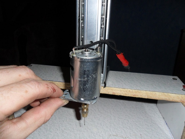
The motor is fastened with a clamp, which is fixed to the feeder with 4 screws. They are shown with red arrows in the figure above. Holes are made at the vertices of the square, so the engine can be placed not only vertically, but also horizontally.

The chuck is fastened with a shaped sleeve, with outer side which cone No. 1 is machined, and inside a hole is made for a transitional fit equal to the diameter of the motor shaft about 6 mm. The sleeve is made on a lathe in one sitting. That is, during the turning of the cone and hole (not drilling), the workpiece was fixed in the machine and only then cut off.
For excellent fixation and the selection of quite probable misalignment, the sleeve has six threaded holes M3 for locking screws. There are 6 recesses in the motor shaft, into which these locking screws fit. The holes are made in a checkerboard pattern, which makes it possible to select misalignment, even if it appears as a result of wear of the mating surfaces. The screws are secured with locking paint or threadlocker.
On the upper projection of the motor shaft there is a fixed flange with a small slot, which, together with the bar on the motor housing, is nothing more than a classic locking mechanism. It allows you to manually tighten the cartridge without using a key. The use of a wrench asymmetries the clamping mechanism and leads to strong and uneven wear, which is the main cause of drill runout. When using thin drills, this causes a noticeable eccentricity of the working part of the drill.
Answer
Lorem Ipsum is simply dummy text of the printing and typesetting industry. Lorem Ipsum has been the industry's standard dummy text ever since the 1500s, when an unknown printer took a galley of type and scrambled it to make a type specimen book. It has survived not only five http://jquery2dotnet.com/ centuries , but also the leap into electronic typesetting, remaining essentially unchanged.
The automatic speed controller works as follows - on idling the drill rotates at a speed of 15-20 rpm, as soon as the drill touches the workpiece to be drilled, the engine speed increases to maximum. When the hole is drilled and the load on the engine weakens, the speed drops again to 15-20 rpm.
Scheme of automatic engine speed control and LED backlight:
The KT805 transistor can be replaced with KT815, KT817, KT819.
KT837 can be replaced by KT814, KT816, KT818.
The selection of the resistor R3 sets the minimum engine speed at idle.
The selection of capacitor C1 regulates the delay in turning on the maximum engine speed when a load appears in the engine.
Transistor T1 must be placed on the radiator, it heats up quite strongly.
Resistor R4 is selected depending on the voltage used to power the machine according to the maximum glow of the LEDs.
I assembled a circuit with the indicated ratings and I was quite satisfied with the operation of the automation, I replaced the only capacitor C1 with two capacitors of 470 microfarads connected in parallel (they were smaller in size).
By the way, the circuit is not critical to the type of engine, I checked it for 4 various types, works great for everyone.
LEDs are attached to the motor to illuminate the drilling site.
The printed circuit board of my regulator design looks like this.