Do-it-yourself wooden planer drawings. Do-it-yourself jointing machine based on an electric planer. Tool pre-assembly
The drawing of a hand-made wooden planer consists of five components:
block
clamping wedge
front handle
rear handle
knife
metal tale
Details of every detail
Reference: for the manufacture of wooden parts birch, pear, ash, maple, beech, hornbeam wood is used; wood should be healthy, straight-grained, the fibers are directed along the longitudinal axis, the humidity is not more than twelve percent; give preference to the swampy part of the trunk.
BLOCK


In the manufacture of pads, special attention should be paid to:
1. The plane of the notch bed on which the knife lies should be flat, made at an angle of 45 ... 50˚.
2. The knife must be free to enter the notch. The width of the notch should be greater than the width of the knife by 1.0 ... 1.5 (mm).
3. It is necessary to achieve a perfectly flat surface of the sole.

For this we take thick glass(12 ... 15 mm), we check its plane by applying a metal ruler to the surface, if there are no gaps, then the glass surface is ideal and you can move on.
We stick sheets of paper on the glass, with different grain sizes (100 ... 320).

We start with the largest grit and end with the finest.
To check the readiness of the surface of a wooden block hand planer, let's put four lines on it: one at the beginning of the spout; one at the end of the heel; one before the slot; one after the cut. If the marker disappears evenly along all four lines during grinding, then the surface of the sole of the last is ready.
4. The shoulders support the wedge. With top width they taper towards the bottom and have zero width.
CLAMPING WEDGE

The angle of inclination of the wedge and the angle of the cheeks should be the same. This is necessary for a good clamping of the knife.
HANDLE FRONT

The shape can be any, convenient for the grip of the hand.
REAR HANDLE

On the one hand, it should contain a plane that is parallel to the notch bed and is its continuation.
On the other hand, it should contain a circular pas for a comfortable grip by hand.
In the present age innovative technologies in production, hand tools are rarely used, and in mass production they are not used at all. However, there have always been, are and will be craftsmen - cabinetmakers, for whom working with wood is not only part of the business, but also a favorite pastime.
For them, making a product with their own hands is always a pleasure. Such specialists have a lot of hand carpentry tools in their workshop.
Introduction
Planer types
A planer is a hand tool for woodworking, which allows you to bring the surface of the product with your own hands to the required quality and size. Having the whole set of types of this tool, you can not only process the surface, but also make various carpentry crafts.
Planer has a whole arsenal of types:
Flat planing:
- sherhebel;
- jointer;
- semi-joiner;
- bear;
- sander;
- cynubel;
- end face;
- single;
- double.
Shape planing:
- zenzubel;
- federgubel;
- false bed;
- headquarters or headquarters;
- tongue and groove;
- mold;
- grubbel;
- hunchback
Having the whole set hand tools, if desired, you can make works of wood of any complexity. At the same time, an important factor successful work is the do-it-yourself sharpening of planer knives, which is an expensive production service.
Of the curly planers, the zenzubel stands out with useful features. It is used for the manufacture of grooves, quarters, stripping and finishing to the right sizes spikes and cuts. The manufacture of this type of instrument will be discussed.
The article outlines an algorithm for how to make a planer with your own hands.
additional information
All of the tools listed above are standardized products. Therefore, in order for them to perform their work correctly and accurately, they must be manufactured in accordance with the requirements of GOST 15987-91. Below are extracts from GOST that define the basic requirements.

materials
The list of required materials from which you should make a manual planer with your own hands:
- ash;
- maple;
- hornbeam;
- white acacia;
- birch (allowed).
The wood must be well dried, without knots, cracks and rot. For gluing parts, you must use waterproof glue.
Requirements for the metal used
Knives are made from the following types of two-layer steel:
- the main layer is made of brand 30, GOST 1050, (U8, U8A, U9, GOST 1435 is allowed);
- cladding layer - from grades 9ХФ, 9Х5ВФ, Х6ВФ, 9ХС, GOST 5950.
It is allowed to use metal of other grades, but not worse than those given in the standard. Knives must be perfectly sharpened, and have an appropriate sharpening angle.
Tip: in order for the tool to work, the surface to be machined is decent quality, in the workshop it is desirable to have a device for sharpening the planer with your own hands.
Preparation for work
To make a planer with your own hands, you need to prepare the following tools.
Equipment and tools
| Name | Quantity |
| Ruler | 1 |
| Joiner's goniometer | 1 |
| Pencil | 1 |
| Reismus | 1 |
| Circular saw | 1 |
| Electric jigsaw | 1 |
| Drill | 1 |
| Drill, 10 mm | 1 |
| Planer | 1 |
| Miter saw | 1 |
| Band-saw | 1 |
| Vertical drum grinding machine | 1 |
| Milling machine | 1 |
| Finger cutter, 10 mm | 1 |
| Half round cutter | 1 |
| Chisel, hammer | 1 |
| Metal file | 1 |
| Clamps | 8 |
Materials and accessories
| Name | Type and dimensions, mm | Quantity |
| metal knife | according to the drawing | 1 |
| Light wood | Ash 270x100x25 | 1 |
| Wood dark | Oak 200x80x15 | 1 |
| Glue | Carpentry waterproof | 1 |
| Sandpaper | Grain 100, 500X100 | 1 |
| Sandpaper | Grain 600-800, 500x100 | 1 |
| Varnish on wood | Colorless, waterproof | 50 g |
Description of the manufacturing process

The material of the heel, nose and sole of the planer is ash. Cheeks and wedge - oak. The thickness of the planer should be equal to the width of the knife blade, 20 mm.

Then you need to cut a hole for the hand. For this:
- Using a drill, drill holes of 10 mm for a file;
- An electric jigsaw makes a cutout for the hand along the marked contour;
- On the grinding machine handle inner surface holes.


If the workshop has mastered such an operation as sharpening a planer with your own hands, then the angle of sharpening the blade should be equal to 45 degrees so that the protruding cutting edge knife was parallel to the plane of the sole.
To do this, the oak blank is cut into two halves, the surface and ribs are cleaned with a planer.


Similarly, a cutout is made on the second cheek. On both cheeks, with the help of a trimmer, a hacksaw and a chisel, a hole for the knife is cut out.


At the next stage, you need to glue all the parts into a single structure with your own hands. First, the nose and heel are glued to one cheek. To do this, carefully smearing the parts with glue, apply and press with clamps. After drying, glue the second cheek on the opposite side.

After the glue dries, the workpiece is finally cut along the contour on the band saw and the outer and inner edges are manually processed on the grinding drum. semi-circular cutter milling machine all sharp edges of the planer blank are processed on both sides.


In conclusion, it is required to carefully grind the entire planer blank by hand. Of particular importance is the quality of the sole, which is the working part of the tool. The purity of the workpiece depends on its condition.
The processing of the flat sides of the workpiece is done by hand, using sandpaper pressed against a perfectly flat surface. For this, a planer plate is suitable. First grind sandpaper with grain 100-150. The sole is brought to a “mirror state” with a grain of 600-800.
Important! In order to check the quality of the surface of the planer with your own hands, you can use the thinnest probe for measuring gaps. The test is carried out on both sides of the sole.

The tool is coated with a waterproof colorless varnish, and the do-it-yourself planer is ready.
Conclusion
With this tool, in addition to making grooves and sampling quarters, it is very convenient to make thin cleaning of surfaces, trimming corners, which are difficult to handle manually with a chisel.
For a better mastering of the manufacturing process, it is recommended to watch the video.
Do-it-yourself planer video
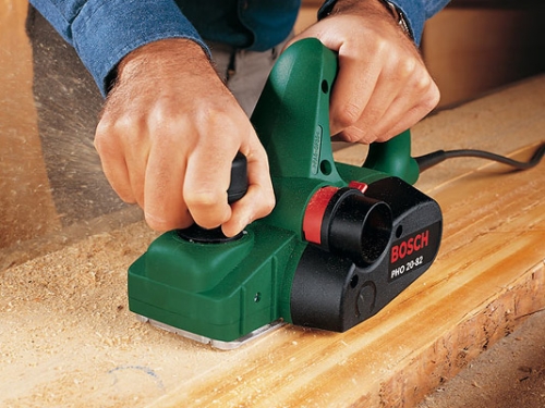
For many, working with wood brings great pleasure. It's nice to make a table for the veranda with your own hands, assemble garden bench or change a leaky board. Only the joys of creativity are overshadowed by the routine physical work that electric planes are designed to deal with. Everyone, even a beginner, can work with a manual electric planer.
The purpose of the electric planer
The planer is the oldest woodworking tool after the axe. Any professional treats him with special respect. The painstaking work of the designers and the electricity of the planers made it even more perfect and efficient. Thus, modern electric planers outwardly resemble their mechanical counterparts, however, new designs are several times more productive than manual labor.
The electric planer is intended for processing wood, reducing the thickness of wood products, preliminary planing, fitting, processing boards on a frame, beveling edges and creating an extended recess in products various shapes(chamfers, quarters, tongues). All this is called by one term - planing. This tool is not suitable for processing larger area, but at low volumes it makes it easier for the frequent repairer or woodworking professional.

The main function for a planer is to level a wooden surface that has previously been roughly processed. After leveling the product with a planer, all irregularities and defects disappear from the surface, and it becomes extremely smooth. Finishing wood is usually done with a grinding planer. With an electric planer, you can also make a chamfer or groove in the workpiece.
The design of the electric planer
The design of an electric planer is quite simple. Let's take a closer look at the electric planer circuit and its constituent elements.
Rotating drum
In the body of the electric planer on base plate the main working element is located - a rotating drum on which knives are attached. As a rule, in the "knife drum" there are two, less often three or one, knives, which are engaged in cutting the upper surface of the planed wood. The knife shaft is much more technologically advanced than a conventional cutter, and the power of the tool allows you to work without any additional effort.
Knives are made from tungsten, hardened steel or carbide. According to the number of knives that are fixed on the drum, electric planes are "two-legged" and "one-legged". The first type of tool works only with precise alignment, otherwise only one knife will work, the second is simple and productive. Electric planers with a knife, which is fixed obliquely on the drum, are able to make a specific “spiral” cut for high-quality planing of the board.

Over time, knives wear out. There are reusable knives that need to be sharpened or disposable knives that need to be changed. The frequency of these procedures is largely determined by operational loads: the type of wooden surface and the time of their processing.
To remove the knife, slightly loosen the bolts that press the knife holders. They are easily removed from the grooves of the drum. Knives after sharpening are put in place, leveling in height with each other, as in the video about the electric planer.
Due to the presence of a centering groove, straight carbide knives are easily mounted in their place in holders, which are inserted in turn into the grooves of the drum. Sharpened steel knives need more careful height alignment.
Electric planer sole
The sole of the electric planer is made of cast aluminum and is divided into 2 parts relative to the drum - front and rear. The rear part is fixedly attached, while the height of the front part, which is able to move on the still untreated wood, can be set using a knob or a button. The position of the front part primarily determines the depth of planing or, in other words, the thickness of the chips.

The sole affects the stability of the electric planer. In any case, this element should not interfere with work and be smooth. The soles, which are produced by some manufacturers, have several V-shaped grooves in their surface, which are needed for chamfering the corners of the workpiece.
Electrical part
The rotating drum is connected to an electric motor by means of a drive belt, which is responsible for the transmission of rotational motion. The drive belt needs to be changed from time to time. But this activity is not at all troublesome, because belts are sold in all tool stores. The old belt can be dismantled independently. To facilitate this operation, manufacturers protective cover made removable.

The electric motor has a power of 580 - 900 W, its rotation speed reaches 1000 rpm. The quality of the treated surface depends largely on the engine power. The electric planer device has a switch with a lock and a cord with a plug, as well as various electronic components: changes or stabilization of speed, soft start, drum balancing, overload protection and even an electronic brake.
Tool handles
Two handles are used to move along the working surface of the electric planer. The back of them allows you to push the tool, it has a start / stop trigger with a double security system. With the help of the front additional handle, they only direct the movement of the electric planer, the same handle allows you to work “on a grand scale”. If you press hard on the front handle, then at the end of the processed material you can remove large layer wood.

Since the adjustment knob is sometimes used as a second knob, it is often made with internal notches so that it can be raised when switching, otherwise it is possible to knock down an inadvertently set chip thickness during operation. A handle without such notches is able to adjust this parameter on the go, but this does not allow you to get rid of unwanted switching.
The switching step is usually 0.1 millimeters, but each electric planer has its own differences. The cutting depth can be set by turning the knob. At the same time, the front part of the sole drops or rises, opening the drum with knives less or more.
Knife protection
Two types of protective devices protect the work surface and fingers from below and to the side from contact with the knives. At the bottom of the sole there is a leg, as in the photo of an electric planer, which is automatically ejected, slightly lifting the back of the sole. The movable safety leg will recline when the electric planer is not working and protect the workpiece from contact with the knives. Also, the planer can be laid on its side, with the drive belt cover down.

The protective plate on the side of the spring closes the edge of the knife drum and rises as much as the planer will go deep into the wood when choosing a quarter. The side edge of the knife drum, which allows you to select a quarter, is hidden under the turning plate.
Chip ejection
The direct chip ejection procedure eliminates clogging of the electric planer and occurs in three ways. In the first case, technical excesses are not required, the chips will scatter throughout the room, however working surface will not clog.
The possibility of directing the ejection chute in some models facilitates the removal of chips, this is the second option for ejecting chips. The bag holds a large amount of chips, although it is not too bulky. If you need a bag, you should ask if there is one in the kit and if it is possible to buy it in addition.

A good solution to the problem is to connect with corrugated hose to a vacuum cleaner, but even he will not be able to completely rid you of debris. Depending on the location of the operating electric planer, it is convenient to direct the ejection of chips in a certain direction.
To do this, you just need to switch the key to the desired position. The method is simple, but inconvenient in some cases, because the hose and cord limit the maneuverability of the structure.
Electric planer accessories
There are many different accessories for the tool, regardless of the price of electric planers. For example, wavy knives made of hardened steel, different overall dimensions, which are used for roughing, as well as equipment that allows you to install a planer motionless and turn it into planer and automatic jointer at the same time.
The side stop, together with the depth gauge, is able to accurately set the width and thickness of the chip being removed. To cut a corner, it is customary for some limiters to tilt from 0 to 45 degrees. When planing a thin edge, the side stop will help to give the planer the necessary balance. Of all the accessories described above, of all possible ones, they must be included in the kit.
Specifications
The power of the electric planer is 0.4 - 2 kW. For home use and do-it-yourself repairs, an electric planer is suitable, which has a power of 500 - 900 watts. For simple and short-term work, a household-class electric planer or a home-made low-power electric planer is suitable. And for real masters, you only need a professional powerful tool.
The rotation speed of the cutter can affect the surface finish and is 10 - 18 thousand revolutions per minute. In some models, the rotation speed can be changed. It is also able to be maintained at a constant level by electronics, which, when working with hard rocks wood is very convenient.

The planing width is 82 millimeters or more. This figure matters when you spend most of your time working on boards. For many companies, the planing width of wood usually does not exceed 82 mm, but there are companies on the market, for example, Interskol, which have increased the planing width to about 102 millimeters.
You can set the depth of planing within 0 - 4 millimeters. It is smooth and step by step. The edge sampling depth ranges from 0 to 25 millimeters, respectively.
Making an electric planer with your own hands
The electric planer that you will be making is designed to process in one pass wood that has a width of up to 120 millimeters and a processing depth of up to 1.2 millimeters. The workpiece will rest on a plate with a hole for the knife shaft. The guide square is attached to the base plate with 2 screws M8, which have plastic heads, it prevents the lateral displacement of the product during processing.
They are attached to the base plate from below with M6 screws, which have countersunk heads, bearing support of the knife rotating shaft. It is customary to install a V-belt pulley outside the base plate at the end of the knife shaft. The plate is fixed with 10 screws to the body of the electric planer, which is welded from a steel corner measuring 20 by 20 by 3 millimeters.
The protective casing is connected to the body with three M6 screws with cylindrical heads above the V-belt transmission through spring washers. The electric motor of the tool is placed inside the body and connected to it by means of 2 supports in the form of steel strips. They have 2 holes with a diameter of approximately 6.5 mm, which are designed for mounting on the body of the electric planer with their own hands, as well as 2 grooves each for installing and adjusting the position of the electric motor to tension the belt.

The electric motor of the device is controlled from the remote control located on the front of the case. Under the U-shaped bracket inside the remote control there are 2 phase-shifting capacitors, which are fixed in parallel and have a capacity of 4 microfarads. The switch is mounted outside on the console. From direct hit of dust and shavings the motor is protected by a casing.
First of all, make a base plate. The most time-consuming operation is the execution of a figured slot in the plate, which is intended for the exit of knives. To do this, use an electric drill with a small diameter cutting wheel or drill along the contour of the hole, and then file the slot. After drilling the mounting holes in the base plate, threaded holes are made along them in 4 upper corners of the electric planer body.
Before welding, the upper corners are attached to the base plate with 10 screws, the remaining corners of the body are attached to them by welding. Then the base plate is removed, and the body is finally welded along the contour, cleaning the welds. Particularly carefully cleaned along the plane in which the housing is adjacent to the base plate. At the same time, gaps are unacceptable, because they provoke vibration during the operation of the electric planer. Consider this before you make an electric planer with your own hands.

Make sure after assembly that the cutter shaft will rotate counter-clockwise - in the direction of feed, as judged from the console. This feature has great importance, because the technique of fixing the V-belt pulley on the knife shaft does not allow it to move in reverse side. Fasten the planer body without gaps with 4 M6 screws before starting work.
The knife shaft for cutting grooves is equipped with 2 knives that have a width of 120 millimeters, or one knife. On the opposite side of the shaft, in the latter case, a counterweight is installed to eliminate imbalance and vibration. Each knife is fixed with pressure plates and 3 M8 screws, which are screwed into the through threaded holes of the rotating knife shaft.
For knives, the most affordable blanks are the worked-out hacksaw blade for metal, which has a thickness of about 3 millimeters. The sharpening angle of the cutting edge of the knives should be within 30 - 40 degrees. With curly sharpening, you can get a relief surface for artistic frames or platbands.
Narrow and thin profile strips that have a width of less than 10 millimeters can be prepared by ripping a wider board. When working with narrow knives (less than 12 millimeters), it is not recommended to process grooves that have a depth of 8 millimeters, due to a lack of tool strength.
Now you know how to make an electric planer, it remains to learn how to properly sharpen knives for it. We'll talk about this in the next article.
The drawing of a hand-made wooden planer consists of five components:
block
clamping wedge
front handle
rear handle
knife
metal tale
Details of every detail
Reference: for the manufacture of wooden parts, wood of birch, pear, ash, maple, beech, hornbeam is used; wood should be healthy, straight-grained, the fibers are directed along the longitudinal axis, the humidity is not more than twelve percent; give preference to the swampy part of the trunk.
In the manufacture of pads, special attention should be paid to:
1. The plane of the notch bed on which the knife lies should be flat, made at an angle of 45 ... 50˚.
2. The knife must be free to enter the notch. The width of the notch should be greater than the width of the knife by 1.0 ... 1.5 (mm).
3. It is necessary to achieve a perfectly flat surface of the sole.
To do this, we take thick glass (12 ... 15 mm), check its plane by applying a metal ruler to the surface, if there are no gaps, then the glass surface is ideal and you can move on.
We stick sheets of paper on the glass, with different grain sizes (100 ... 320).
We start with the largest grit and end with the finest.
To check the readiness of the surface of the wooden block of the hand planer, we will draw four lines on it: one at the beginning of the spout; one at the end of the heel; one before the slot; one after the cut. If the marker disappears evenly along all four lines during grinding, then the surface of the sole of the last is ready.
4. The shoulders support the wedge. From the top width they taper to the bottom point and have zero width.
The angle of inclination of the wedge and the angle of the cheeks should be the same. This is necessary for a good clamping of the knife.
The shape can be any, convenient for the grip of the hand.
On the one hand, it should contain a plane that is parallel to the notch bed and is its continuation.
On the other hand, it should contain a circular pas for a comfortable grip by hand.

The knife should be selected from A2 steel, 2.4 mm thick, which has undergone a special heat treatment. Before installation, it is necessary to sharpen the cutting edge, align and polish
Can be done from metal bolt, washers and nuts. The baek serves to remove the blade from the block, by easy hitting the bike with a hammer.

The proposed model proved to be excellent in work.
How to make a do-it-yourself planer simply and effectively
In order to carry out work with curved or concave bases, they came up with hunchbacks-moulders, with the help of which textured planing is performed. wooden blanks. These elements have a special shape. They do not have special advantages in comparison with planers. In addition, it is quite problematic to work with such devices. In order for the processing of parts to be of high quality, it is necessary to gain some experience in such work, as well as special skills.
To date, it is very difficult to find kalevka in construction stores, since almost all stores sell electronic engineering. It is for this reason that it is much easier to make a planer yourself.

The iron element will determine the dimensions of the homemade planer body, therefore, first of all, it is necessary to start manufacturing the iron element, as well as the chipbreaker. For a planer of small dimensions, you can take an iron element from an old product, and for a device with oval-shaped elements, you can purchase "pieces of iron" in any hardware store. Such devices are littered along the radius initially, you can buy them together with suitable chip breakers. The planer drawing is very simple and understandable, almost anyone can create it.
Selecting and processing workpiece
In a significant part of all cases, planers are made from the most common types of wood - maple, birch and others. The workpiece must be made 30-50 millimeters larger than the final dimensions of the manufactured device. The width can be determined using the following formula: the dimensions of the "piece of iron" + 3 mm + on the cheeks 20 mm + additional 6 mm for the possibility of processing on the machine. If the planer is made of small dimensions, then the cheeks may have a thickness of about 6 mm.
The instrument should be marked so that the rings are parallel to the sole, and the fiber goes down to the back from the front. So that after sawing all parts of the structure can be connected correctly, a triangle should be drawn on the front of the block, the top of which looks up.
First of all, it is necessary to make two parts of the middle section, between which a “piece of iron” and a chipbreaker are fixed with a wedge. Then you need to fix 2 cheeks.

The body of the planer is assembled from a workpiece, which is sawn into two parts. Cheeks are cut out band saw. Then the middle section is sawn into several elements. At the same time, it will be necessary to make a bed of the iron element, as well as a distance for the chipbreaker. A wedge can be cut from a cut that will no longer be used. At the end of the assembly, the sole and body must be processed into shape. At the end, the planer is adjusted.
Note that the middle element should be 1 mm wider than the piece of iron. In addition, take into account the allowance of 1 mm for processing the middle part of the tool up to rectangular shape. Cheeks can be marked using a saw. We place the bed of the piece of iron at an angle of 45 degrees, so the chips can come out without any difficulties. The notch of the front opening is placed at an angle of 60 degrees. I saw the middle element into the front part - the toe and the back part - the heel.
Then you need to make a simple template from plywood sheets, with which you select the groove for the screw head, it ends at a distance of about 20 mm from the bottom of the case. The groove can be selected with a chisel.
Tool pre-assembly
When making a homemade planer, it is necessary to slightly process the mouth of the middle element with a file, using the outline of the "piece of iron". Then the rear part of this section is placed on the edge, the iron element is put in place, and then the front part is pushed up to it. In the end, you need to check the correct fit.
After that, the structure is moved apart so that a gap of 3 mm appears between the components of the middle element of the planer for a “piece of iron” with a thickness of 4.5 mm, which forms the mouth of the tool. Further, all parts of the structure will need to be aligned and compressed. Through the cheeks in the middle section on the two sides, holes will need to be drilled so that the dowels can be installed and glued.
It is worth noting that a significant part of the planes has the shape of a rectangle, so you should not waste time ennobling the design.

In the side parts, you need to choose small holes for the fingers, if they are available, it will be convenient to hold the tool. Corners need to be chamfered.
When the planer has its final shape, it will be necessary to saw off the chamfers. Until that time, they will be able to guarantee the exact alignment of all parts so that the adjustment of the cross rod can be carried out. So that during the gluing of the parts of the structure, the dowels do not interfere, it is necessary to saw them flush with the cheeks.
Completion of tool making
On the extreme parts of the rod, you will need to mount round spikes, they will go into the holes in the cheeks. Thanks to these spikes, the structure will be able to rotate at an angle to the wedge. In order to be able to make holes for the rod on the top element of the planer, an additional line should be drawn at an angle of 90 degrees to the side parts. After that, 1 cheek is removed from the assembly, and with the installed “piece of iron” and a chip breaker, the line is transferred to another cheek. The second cheek is removed from the middle part and, with a gap of 20 mm from the bottom of the tool and 12 mm from the top of the chipbreaker, mark the center of the hole intended for the rod.
Note that in order to guarantee the exact location of the hole in the rod, it must be done on a drilling device.
The cheeks are aligned along the drawn lines, then they are compressed with clamps, after which a hole is drilled.
You can make a rod from a bar, which has a section of 12 * 12 mm. The length of the rod should be equal to the width of the structure, taking into account the cheeks. The length of the spikes is determined based on the thickness of the cheeks. At the ends of the rod, four shoulders must be made. Next, the spikes are rounded with a knife.

In order for the chips to exit uninterruptedly, it is necessary to round off the upper ribs of the middle part of the rod. After the rod is ready, you need to check its fit to the tool. The rod should rotate without problems.
Final Assembly of the Element


Video about little wooden planer do it yourself
After fitting the rod, you need to check the location of the dowels and spikes. These parts of the structure should be flush with the cheeks. All parts will need to be glued and secured with clamps, while the cheeks must be protected with gaskets. When the glue dries, it is necessary to start cleaning the protruding solution. In order to be able to level the sole over the joints, it is necessary to walk over the product once with a planer.
The wedge can be made from cutting from the middle part, it must be installed between the rod and the chipbreaker. If the wedge is flat, it will be hard to knock out. If the angle is too large, then the wedge can be knocked out even with minor blows.
After the planer is assembled, it will be necessary to make a sole and remake the mouth in order to finally fit it to the iron element, taking into account the purpose of the manufactured product. A narrow gap in front of the "piece of iron" is a prerequisite in order to finely remove chips. And a gap of 0.8 mm is more suitable for coarse chips.
The most labor-intensive part of making a planer is fitting the mouth of the tool to the piece of iron. The letok must be rounded according to the bends of the iron element. This can only be done through a small opening in the sole of the planer. If the product is made to remove thin chips, then care must be taken to ensure that the gap of the mouth is as narrow as possible.
The iron element should be fixed at the uneven line of the front part of the middle element, then begin to attach correct form sole. To do this, you need to clamp the manufactured product in a vice with the sole up and from the ribs to the middle, where you need to remove some wood. Then the design should be processed with a planer with a flat sole.

When a distance of 0.8 mm remains in the planer to the radius of the “piece of iron”, you need to switch to the cycle. They do this in order to be able to remove traces of the planer. Then a fine skin is fixed on the plate and the lower part of the planer is cleaned with long equal passes, while rocking the tool from side to side. Then they examine the contours of the sole of the "piece of iron". At the end, the sole of the micron skin should be cleaned, which is attached to a flat base.
After stripping, the piece of iron will not be able to pass through the mouth of the product. For this reason, it is necessary to remove the wood in front of the "piece of iron" with a small file. Remove until the iron element matches the mouth. As a result, the “piece of iron” should come out of the sole a little.
If the quality of the product made suits you, then the tool can be varnished. On the sides of the planer, it is advised to apply an additional layer of varnish.
Note that during the gluing of all parts of the product, it is necessary to remove all excess glue in a timely manner, which can stick out after being compressed in the vice of a planer.
Making a planer out of wood is not difficult if you take into account all the available nuances. Must comply correct order actions, as well as have all necessary materials and tools.
How to make a do-it-yourself grinder

It is extremely useful, fits comfortably in the hands and is inexpensive to manufacture. This beautiful instrument will make your lips stretch into a smile when you feel the beauty of working with him.
Overall dimensions, homemade planer mm: 54x178x76 (width x length x height)
The cost of high quality planers with wooden inserts, which are produced in limited series, is measured in hundreds, and sometimes thousands of dollars. This tool is similar to them, but it is smaller and more convenient, and better suited for working with small details. Craft it from inexpensive maple wood with contrasting exotic porosity accents, adding an S25 blade.
How to make a planer block
1. Start with a maple blank measuring 64x60x230 mm. Mark vertical and oblique lines on the side face (Fig. 1) and extend them to the other three [workpieces. Using a drill press, make a 6mm hole in the center of the workpiece. Then drill four 6 x 25 mm holes in the corners on both sides (photo A).
2 Saw off cheeks A from the workpiece (photo B) and draw lines again on the rest of the workpiece. Cut the workpiece along the marking so that the saw blade passes close to the lines, and separate the heel B and toe C (photo C).
Add a planer sole to the block
1 Assemble the last by gluing cheeks A, heel B, and toe C together (photo D). When the glue dries, sand the underside of the last to make it flat. Brief advice! Use spray adhesive to attach a piece of sandpaper to a cast iron table saw or a piece of thick glass to level the underside of the block.
2. To add a durable outsole D, glue a 19x57x185 mm cocobolo piece to the underside of last A/B/C, center aligned, and secure with clamps.
3. With a pencil, mark the thickness of the sole D by drawing a line parallel to the bottom edge of the shoe at a distance of 3 mm. Remove with a band saw excess material(photo E). (- save the cut to make a wedge of it E. Then file the protruding edges flush with the cheeks of the last. Sand the sole in the same way as before and remove all traces of sawing.
Form a mouth
1. Extend the oblique marking lines from the cheeks A to the underside of the sole D. Drill holes for the mouth (photo F) and trim the edges with a chisel (photo G).
2. Make a copy of the side template of the last (Fig. 1), and attach to one and: * Cheeks A using spray adhesive. Cut along the contour with a band saw (photo H), then widen the gap of the mouth so that a planer blade can pass through it (photo I).
Finish planer to final shape and add wedge
1. Glue a 6 mm brass rod into the holes of the cheeks (Fig. 2, photo J) and align its ends flush with the cheeks A using a file.
Then make a copy of the profile template (Fig. 3) and stick it on a piece of thick cardboard. Carefully cut out the template along the contour lines and mark the shape of the bell with it (photo K). File off the excess material with a band saw and sand the planer smooth.
2. Mark and cut the wedge blank E from the rest of the sole blank (photo L). Sand the beveled edge flat and check how the wedge fits into the shoe (photo M). Further sand or file the clip so that it fits snugly between the brass rod and the blade.
Note. If you have the same rounded blade for the Scherhebel planer, make it square before sharpening it at a 25° angle. We also shortened it to 95 mm with a hacksaw, but you can leave the original length and this will not degrade the properties of the blade.
3. File the wedge to the final length and shape (Fig. 4). Then round off the top corners of heel B and toe C to make the planer comfortable to hold. Sand all the flying with #220 sandpaper and apply wax paste for finishing. Use a wooden mallet to adjust the blade reach. If you hit it lightly on the heel of the block, the blade will retract and the chips will be thinner. With light strokes on the blade, it can be extended, as well as tilted to the right or left.
Do-it-yourself planer - photo

A. The workpiece is first sawn into pieces, which are then glued together again. Auxiliary holes will help to accurately align them when gluing.
B. Saw off cheeks 6 mm thick from the workpiece. To safely guide a short workpiece and control the cut, use a pusher from a wide board cut.
C. To keep your fingers at a safe distance from the blade and make precise miter cuts, clamp the workpiece to the cross fence pad.
D. Apply glue evenly on heel B and toe C, glue cheeks A and insert 25 mm dowels into the holes.
E. Sole blank D protrudes beyond the cheeks of the last. To keep the block horizontal when sawing, attach double sided tape 6 mm board.
F. With a 5mm center point drill, carefully make a series of holes between the marking lines and remove excess material at the edges of the gap.

G. Resting the blade on the bevels of heel B and toe C, guide the chisel to trim the edges and corners of the gap, removing excess.
H. While cutting along the dotted lines of the template, remove the dowel ends and shape the last into the shape shown.
I. Widen the gap first with a coarse file, then file the surfaces with a velvet file until smooth.
J. Apply cyanoacrylate ("second") glue to the top edges of the holes so that the inserted brass rod will push the glue into the depth.
K. Using a cardboard profile template, draw smooth lines from toe to heel. Press the template firmly so that it does not move.
L. Mark a 10° angle on the edge at one end of the workpiece. Tape the blank to the rectangular cut and cut along the line with a band saw.

M. Insert the blade into the block, then the wedge blank (without shortening it yet) and make a few light blows with a mallet. Dents will appear on convex places.
List of materials and parts
Do-it-yourself electric planer

For many, working with wood brings great pleasure. It's nice to make a table for the veranda with your own hands, assemble a garden bench or change a leaky board. Only the joys of creativity are overshadowed by the routine physical work that electric planes are designed to deal with. Everyone, even a beginner, can work with a manual electric planer.
The purpose of the electric planer
The planer is the oldest woodworking tool after the axe. Any professional treats him with special respect. The painstaking work of the designers and the electricity of the planers made it even more perfect and efficient. Thus, modern electric planers outwardly resemble their mechanical counterparts, however, new designs are several times more productive than manual labor.
The electric planer is intended for processing wood, reducing the thickness of wood products, preliminary planing, fitting, processing boards on a frame, beveling edges and creating an extended recess of various shapes in products (chamfers, quarters, tongues). All this is called by one term - planing. This tool is not suitable for processing a larger area, but with small volumes it makes it easier for the frequent repairer or professional when working with wood.
The main function for a planer is to level a wooden surface that has previously been roughly processed. After leveling the product with a planer, all irregularities and defects disappear from the surface, and it becomes extremely smooth. Finishing wood is usually done with a grinding planer. With an electric planer, you can also make a chamfer or groove in the workpiece.
The design of the electric planer
The design of an electric planer is quite simple. Let's take a closer look at the electric planer circuit and its constituent elements.
Rotating drum
In the body of the electric planer, on the base plate, there is the main working element - a rotating drum, on which the knives are attached. As a rule, in the "knife drum" there are two, less often three or one, knives, which are engaged in cutting the upper surface of the planed wood. The knife shaft is much more technologically advanced than a conventional cutter, and the power of the tool allows you to work without any additional effort.
Knives are made from tungsten, hardened steel or carbide. According to the number of knives that are fixed on the drum, electric planes are "two-legged9raquo; and “one-legged9raquo;. The first type of tool works only with precise alignment, otherwise only one knife will work, the second is simple and productive. Electric planers with a knife fixed obliquely on the drum are capable of making a specific “spiral9raquo; cut for high-quality planing of the board.
Over time, knives wear out. There are reusable knives that need to be sharpened or disposable knives that need to be changed. The frequency of these procedures is largely determined by operational loads: the type of wooden surface and the time of their processing.
To remove the knife, slightly loosen the bolts that press the knife holders. They are easily removed from the grooves of the drum. Knives after sharpening are put in place, leveling in height with each other, as in the video about the electric planer.
Due to the presence of a centering groove, straight carbide knives are easily mounted in their place in holders, which are inserted in turn into the grooves of the drum. Sharpened steel knives need more careful height alignment.
Electric planer sole
The sole of the electric planer is made of cast aluminum and is divided into 2 parts relative to the drum - front and rear. The rear part is fixedly attached, while the height of the front part, which is able to move on the still untreated wood, can be set using a knob or a button. The position of the front part primarily determines the depth of planing or, in other words, the thickness of the chips.
The sole affects the stability of the electric planer. In any case, this element should not interfere with work and be smooth. The soles, which are produced by some manufacturers, have several V-shaped grooves in their surface, which are needed for chamfering the corners of the workpiece.
Electrical part
The rotating drum is connected to an electric motor by means of a drive belt, which is responsible for the transmission of rotational motion. The drive belt needs to be changed from time to time. But this activity is not at all troublesome, because belts are sold in all tool stores. The old belt can be dismantled independently. To facilitate this operation, the manufacturers made the protective cover removable.
The electric motor has a power of 580 - 900 W, its rotation speed reaches 1000 rpm. The quality of the treated surface depends largely on the engine power. The electric planer device has a switch with a lock and a cord with a plug, as well as various electronic components: changing or stabilizing speed, soft start, drum balancing, overload protection, and even an electronic brake.
Tool handles
Two handles are used to move along the working surface of the electric planer. The back of them allows you to push the tool, it has a start / stop trigger; with double security system. With the help of the front additional handle, they only direct the movement of the electric planer, the same handle allows you to work “on a grand scale”. If you press hard on the front handle, then at the end of the processed material you can remove a large layer of wood.
Since the adjustment knob is sometimes used as a second knob, it is often made with internal notches so that it can be raised when switching, otherwise it is possible to knock down an inadvertently set chip thickness during operation. A handle without such notches is able to adjust this parameter on the go, but this does not allow you to get rid of unwanted switching.
The switching step is usually 0.1 millimeters, but each electric planer has its own differences. The cutting depth can be set by turning the knob. At the same time, the front part of the sole drops or rises, opening the drum with knives less or more.
Knife protection
Two types of protective devices protect the work surface and fingers from below and to the side from contact with the knives. At the bottom of the sole there is a leg, as in the photo of an electric planer, which is automatically ejected, slightly lifting the back of the sole. The movable safety leg will recline when the electric planer is not working and protect the workpiece from contact with the knives. Also, the planer can be laid on its side, with the drive belt cover down.
The protective plate on the side of the spring closes the edge of the knife drum and rises as much as the planer will go deep into the wood when choosing a quarter. The side edge of the knife drum, which allows you to select a quarter, is hidden under the turning plate.
Chip ejection
The direct chip ejection procedure eliminates clogging of the electric planer and occurs in three ways. In the first case, technical excesses are not required, the chips will scatter throughout the room, but the work surface will not clog.
The possibility of directing the ejection chute in some models facilitates the removal of chips, this is the second option for ejecting chips. The bag holds a large amount of chips, although it is not too bulky. If you need a bag, you should ask if there is one in the kit and if it is possible to buy it in addition.
A good solution to the problem is to connect with a corrugated hose to a vacuum cleaner, but it will not completely rid you of debris. Depending on the location of the operating electric planer, it is convenient to direct the ejection of chips in a certain direction.
To do this, you just need to switch the key to the desired position. The method is simple, but inconvenient in some cases, because the hose and cord limit the maneuverability of the structure.
Electric planer accessories
There are many different accessories for the tool, regardless of the price of electric planers. For example, wavy knives made of hardened steel of different overall dimensions, which are used for roughing, as well as equipment that allows you to install a planer motionless and turn it into a planer and an automatic jointer at the same time.
The side stop, together with the depth gauge, is able to accurately set the width and thickness of the chip being removed. To cut a corner, it is customary for some limiters to tilt from 0 to 45 degrees. When planing a thin edge, the side stop will help to give the planer the necessary balance. Of all the accessories described above, of all possible ones, they must be included in the kit.
Specifications
The power of the electric planer is 0.4 - 2 kW. For home use and do-it-yourself repairs, an electric planer is suitable, which has a power of 500 - 900 watts. For simple and short-term work, a household-class electric planer or a home-made low-power electric planer is suitable. And for real masters, you only need a professional powerful tool.
The rotation speed of the cutter can affect the surface finish and is 10 - 18 thousand revolutions per minute. In some models, the rotation speed can be changed. It is also able to be maintained at a constant level by electronics, which is very convenient when working with hardwoods.
The planing width is 82 millimeters or more. This figure matters when you spend most of your time working on boards. For many companies, the planing width of wood usually does not exceed 82 mm, but there are companies on the market, for example, Interskol9raquo ;, which increased the planing width to about 102 millimeters.
You can set the cutting depth in the range of 0 - 4 millimeters. It is smooth and step by step. The edge sampling depth ranges from 0 to 25 millimeters, respectively.
Making an electric planer with your own hands
The electric planer that you will be making is designed to process in one pass wood that has a width of up to 120 millimeters and a processing depth of up to 1.2 millimeters. The workpiece will rest on a plate with a hole for the knife shaft. The guide square is attached to the base plate with 2 screws M8, which have plastic heads, it prevents the lateral displacement of the product during processing.
To the base plate are attached from below with M6 screws that have countersunk heads, the bearing bearings of the knife rotating shaft. It is customary to install a V-belt pulley outside the base plate at the end of the knife shaft. The plate is fixed with 10 screws to the body of the electric planer, which is welded from a steel corner measuring 20 by 20 by 3 millimeters.
The protective casing is connected to the body with three M6 screws with cylindrical heads above the V-belt transmission through spring washers. The electric motor of the tool is placed inside the body and connected to it by means of 2 supports in the form of steel strips. They have 2 holes with a diameter of approximately 6.5 mm, which are designed for mounting on the body of the electric planer with their own hands, as well as 2 grooves each for installing and adjusting the position of the electric motor to tension the belt.
The electric motor of the device is controlled from the remote control located on the front of the case. Under the U-shaped bracket inside the remote control there are 2 phase-shifting capacitors, which are fixed in parallel and have a capacity of 4 microfarads. The switch is mounted outside on the console. From direct hit of dust and shavings the motor is protected by a casing.
First of all, make a base plate. The most time-consuming operation is the execution of a figured slot in the plate, which is intended for the exit of knives. To do this, use an electric drill with a small diameter cutting wheel or drill along the contour of the hole, and then file the slot. After drilling the mounting holes in the base plate, threaded holes are made along them in 4 upper corners of the electric planer body.
Before welding, the upper corners are attached to the base plate with 10 screws, the remaining corners of the body are attached to them by welding. Then the base plate is removed, and the body is finally welded along the contour, cleaning the welds. Particularly carefully cleaned along the plane in which the housing is adjacent to the base plate. At the same time, gaps are unacceptable, because they provoke vibration during the operation of the electric planer. Consider this before you make an electric planer with your own hands.
Make sure after assembly that the cutter shaft will rotate counter-clockwise - in the direction of feed, as judged from the console. This feature is of great importance, because the technique of fastening the V-belt pulley to the knife shaft does not allow it to move in the opposite direction. Fasten the planer body without gaps with 4 M6 screws before starting work.
The knife shaft for cutting grooves is equipped with 2 knives that have a width of 120 millimeters, or one knife. On the opposite side of the shaft, in the latter case, a counterweight is installed to eliminate imbalance and vibration. Each knife is fixed with pressure plates and 3 M8 screws, which are screwed into the through threaded holes of the rotating knife shaft.
For knives, the most affordable blanks are the worked-out hacksaw blade for metal, which has a thickness of about 3 millimeters. The sharpening angle of the cutting edge of the knives should be within 30 - 40 degrees. With curly sharpening, you can get a relief surface for artistic frames or platbands.
Narrow and thin profile strips that have a width of less than 10 millimeters can be prepared by ripping a wider board. When working with narrow knives (less than 12 millimeters), it is not recommended to process grooves that have a depth of 8 millimeters, due to a lack of tool strength.
Now you know how to make an electric planer, it remains to learn how to properly sharpen knives for it. We'll talk about this in the next article.
Related Articles
 For every master who does not have at his disposal lathe, the eternal problem in the manufacture of round, cylindrical parts from wood, even such simple ones as tongues, tool handles. Some craftsmen use a conductor for these purposes - a steel plate with a thickness of at least 6 mm with holes of different diameters.
 Quite often in the activities of a radio amateur there are situations when it is simply necessary outside help. For example, when you need to hold a part with one hand, manipulate a soldering iron or other tool with the other, and hold circuit board not enough hands. Some lovers do pretty complex structures"third hand" with the use of various hinges and magnets, we offer very simple and cheap to manufacture holders to help radio amateurs.
An electric planer is one of the main tools for woodworking. Properly tuned, he indispensable assistant in the hands of a carpenter. If, over time, the tool settings have gone astray, or you don’t know how to prepare the electric planer for work, then it is advisable to get specialized advice, which we are ready to offer in this material. Otherwise, all the work when working with an unregulated planer will go down the drain, and there will be little pleasure from such unfortunate work.
Like any tool, the planer must be properly adjusted before work. And an electric planer makes even more stringent adjustment requirements than a hand tool. Therefore, the following actions should be carried out before each work with such equipment.
The only warning before inspecting the tool is to follow the safety advice. So the cutting parts of the planer must be treated very carefully. Indeed, due to the fact that the cutters of this tool are distinguished by their extraordinary sharpness, you can cut yourself on them even in the off state, not to mention the operating equipment. Otherwise, such equipment should be treated like any other power tool.
Procedure for preparing the planer for work
Electric planer engine
The first step is to check the operation of the electric plane engine. To do this, you just need to turn it on at idle. At the same time, the drive should smoothly gain momentum, and having reached the nominal value, it should work smoothly and without extraneous noise and rubbing. After that, it is advisable to check the operation of the power unit under load - when it rests on the workpiece, it should gain momentum and hold them. In this case, no extraneous sounds should be observed.
Then you should check the ventilation holes where the brushes are located. When the electric planer is running, there should be no sparks. If there are sparks, then most likely the ventilation holes are clogged with small chips during operation. They should be blown out with an air jet from a compressor or cleaned with a brush. Given the design and operating conditions of the electric planer, this procedure should be done constantly.
If the described actions did not lead to the desired result, then it is necessary to check the brushes themselves directly. They may have worn out and need to be replaced. If this does not help, and the planer “sparks” when used, or, even worse, it smells of burning, then work should be stopped immediately. It must be taken to the service. If everything is done in time, soon it will again serve you without fail.

Tip: when you want to choose an electric planer, first of all look at the power and number of engine revolutions. For long work power must be at least 750 W, and the number of revolutions must be at least 12,000 per minute.
Planer knives
It is clear that the sharper the cutting edges of the knives, the easier it is for the tool to do its job. Knives should be constantly inspected and sharpened as needed. A sign that the knives are blunt is the planer working harder than usual. It has to be constantly pushed when planing. At the same time, the engine runs for wear, making a characteristic sound of overload. This should not be, because the smooth running of the tool is created due to the high engine power and high shaft speeds, and not due to the muscular strength of the operator.
Sharpening of planer knives, like ordinary knives, is carried out on any grinding machine. The skill of sharpening lies in the fact that the cutting edge is equally even along the entire length. Remember, if your model has several knives, and there can be from 1 to 3, then you should sharpen everything. When the tool is working, they act as one. Changes in sharpening upset the balance of the knives, and immediately “crawl out” in the form of a poor-quality cut.
Tip: Try to buy an electric planer with thick blades. The knives on this model of electric planer are metal plates 20 mm long (do not confuse with the width, which is usually 82 or 110 mm according to the standard). On inexpensive planers, knives are no more than 5 mm, the difference is obvious, and such cutters, like the entire unit as a whole, will last much less.
Power Planer Belt
Few people know that there is a special belt in the design of the electric planer. It transmits the movement from the motor armature to the shaft with knives. But, since it is hidden inside the tool (under its side cover), it is not visible and, accordingly, many underestimate its participation in the work of the equipment. But in vain, because this knot is a closed belt with cut teeth. With the help of these teeth, the movement is transmitted to the shaft. Over time, the belt becomes unusable and stretches. If you have performed all of the above steps, the planer motor is working, but the knives are not under load, then most likely the problem is in the belt.

Tip: buy a planer with a rubber belt. When you want to buy a planer, ask the seller what kind of belt it has: rubber or silicone. Rubber is better, and “walks” longer.
Yes, the advice is simple, but the main thing is to have the will and patience to follow them. The quality of care for your instrument always affects the quality of finished products. Remember this. Carry out preventive maintenance in time, and the repair of the electric planer will not be needed very soon.
How to use a jigsaw: everyday tips
How to use a puncher - basic recommendations
We analyze: which screwdriver to choose
We answer the question of how to choose a drill
If you liked the material, I will be grateful if you recommend it to friends or leave a useful comment.

Table for manual electric planer video - Multi registration

DIY circular saw table

Combined do-it-yourself tabletop
How to do garden shredder do it yourself


Circular table from a manual circular saw with their own

How to make a circular saw from a circular saw with your own hands
Homemade guides for a hand-held circular saw

Do-it-yourself table for a manual circular saw drawings - Boilers for a bath drawing.

pobedpix.com / sawing with a hand saw

Do-it-yourself manual circular machine

Table for hand saw DIY video youtube

DIY table for a manual circular saw
Table for circular saw

Watch online Manual circular (circular) saw Interskol DP-1600-2000 video for free, without registration and without SMS - Nasharit.

Circular saw in the table with your own hands

Circular table Do-it-yourself

Homemade woodworking machines from a circular hand saw - Multi registration

Do-it-yourself hand saw attachment

 For processing small crafts very wood and plywood handy tool it can become a scarf, which is easy to make yourself.
Case 1 (see Fig.) is cut out of copper or bronze 2 mm thick or sheet steel 1.5 mm thick.
A hole is cut in it for the planer blade and four mounting holes are drilled. Clip 2 for the blade and the blade itself 3 are made of steel 2 mm thick; a threaded hole is drilled in the head of the clamp for the M4 forcing bolt.
Repair of an old planer
Wooden handle 4 is cut out of a 32 mm thick pine block or board and connected to the body with two screws through Ø3 mm holes or with a solid pin (for this, a through hole must be made in the handle). The second holes in the planer body Ø 4 mm are designed for a support pin, which can be a nail of suitable thickness.


With this mini-planer, not only the edges of products, but also small surfaces are easily processed.
FORBIDDEN, Aleksandrovka village, Vladimir region
Noticed an error? Select it and click Ctrl+Enter to let us know.
Small stationary electric hook
 A man in whose house many things are carried by his hands has in his arsenal a set of special tools among which, if he works with wood, are also small electric planes that are suitable for planning.
Such a tool can be found in the price-stroy.ru catalog of the online store building materials"Price-Story" is your reliable assistant in construction and repair. The electric plane is mobile, you can take it at any time, for example, to the dacha or in the garage, that is, where it is needed.
Unfortunately, this tool is not universal, for example, if you need to pull a small and narrow stick, you need to fully adjust the workpiece repair; it cannot be done by hand because the tool is in the hands. In addition, it is inconvenient to use it when working with a small part completely covered by the aircraft.
Electric planer, 100mm wide cutter width, equipped with a tool, does not turn the tool in the sleeping device, the above drawback can be avoided, the same 75mm roll blades, but this tool can be improvised by a small appliance plays the role of a console.
This will require a 20mm piece of 450mm x 300mm plywood on a pair of poles each in two pieces that are four pieces that can be made from 10mm plywood in a variety of configurations.
Video works Elektrorubka Interskol
The parts are connected together in such a way that the bed, in which the tool is fixed during operation, has projections and recesses due to its shape.
To accurately configure the strut components, you must first make a poster plate template that will fit snugly on the body planner, and then cut it from the strut half, adjust cutting tool Edge, which is attached to an electric drill.
The details of the remains are fixed together with screws and duralumin corners, screwed onto the substrate.
The stand height is chosen by calculation, so the center of gravity should be as low as possible, so the structure will be more stable. The distance between the body of the instrument and its base is 20mm, and to ensure that the stands are not detached, they can be fixed with a metal bracket.
- A set of power tools for wall repair. Power tools always need repairs to walls or hanging shelves, images.
When working on a wall surface, you need a range of power tools that every home should have.
- Aircraft: the invention continues. Making airplanes is pretty easy. The footwear consists of three parts of oak. The midfoot of the shoe is 1.5mm wider than the seal to allow lateral adjustment. On it at the desired angle
- Garden garden tools The company "ORMIS-Ukraine" presents a new brand - an elite garden and parking tools Manor of the British company - manufacturer of hand tools RemoColor Tools Limited.
Tool yard is beneficial
- Simple grinding system. At the first stage of tool grinding grinding wheel usually has a profile groove (Fig.
one). On the second, the edge of the blade is sharpened and filled. Remains and decks. in rotation
- Universal Shpuntubel is a carpentry tool that brings a narrow rectangular groove - a handle on the edge or on plates, machined building furniture Data at some distance from its edge. During
How to make an electric planer with your own hands?
Accessories that are not in the catalog, you can purchase under the order. When buying a new part, you can check its performance. Each model has its own parts, so you should buy only a product that matches the characteristics, which you can pick up by the code stamped on the old part.
Your order will be processed and delivered anywhere in Russia and Ukraine.
We ship to anyone convenient way, not only in such large cities as Moscow, St. Petersburg, Novosibirsk, Yekaterinburg, Nizhny Novgorod, Kazan, Samara, Kyiv, Kharkov, Dnepropetrovsk, Odessa, Donetsk, Zaporozhye and Lvov, and also to any corner of Russia and Ukraine.
Leave a request and buy for electric planers from a wide range of products from the Detaluga.com online store.
Choose a brand of electric planer