Furnaces heating and heating cooking bricks. Brick heating and cooking stoves: a classic version, a Swede, a Russian stove. Typical heating and cooking oven
A real Russian stove or its possible modifications, even in modern world have not lost their relevance. If we do not consider cases when brick structures are installed in a house that is not constrained by dimensions for design solution, while the task of heating is assigned to more promising systems, brick ovens as the main source of heat are still often found. With the current pace of advancement of civilization in the Russian outback, we can say with confidence that they will meet for a very long time.
Warmth in the house is not the only task that is set for brick devices. The ability to cook food on the stove is implemented by a heating and cooking brick oven. It differs somewhat from the classic oven in the type of ordering in the area where the stove is installed. The remaining fundamental nodes have not undergone any special changes.
Multifunctional stove
Choice of furnace model
If there is a sufficient amount of theoretical and practical material on a narrow topic in the field of construction, few people will miss the opportunity to save a certain amount of money and do the work on their own, because the built brick cooking oven with their own hands excludes paying for the work of the master.
Furnace construction is a long and energy intensive process. Everything is complicated by the preparatory stage, at which it will be necessary to calculate the main parameters, decide on the choice of a furnace model, and get acquainted with the project of this model.
Undoubtedly, excellence from professional craftsmen greatly facilitates the tasks of independent construction. All parameters, drawings, diagrams of various models are collected in a single document called a project. The novice master can only choose the most suitable projects for his tasks and use ready-made standard calculations. But even the choice finished model should be made on the basis of some criteria, and not spontaneously, as many people who have never encountered such a question as heating stoves think.

Ready to start stove
Despite the fact that technical calculations are more related to the furnace and chimney, it is necessary to evaluate the dimensions of the furnace itself and the dimensions of the room in which it is planned to be installed. Bulky brick ovens for a house with hob in a small room. Yes, and the heating process will not become more efficient because of this, because in order to heat large structure, it will take longer to heat up. The size ratio can be found in Runet along with the project.
The location of the furnace will affect the choice of model. Ovens with a stove should be oriented so that the nodes used for cooking go to the kitchen, and the back and side walls heated adjoining rooms. But it's just practical advice and the owner has the right to choose where to fold the stove.
The ordinal masonry scheme presented in the project will allow the construction of one of three types of furnaces: T-shaped, square or rectangular. The T-shaped device is installed in the center of the room, partially making its zoning. It effectively heats several rooms at once. This principle was implemented in peasant huts. First, a stove was built for the house, and then the log house itself was erected.

T-shaped version
The remaining two types can serve as island or wall models.

Ready-to-use oven
The compact oven does not take up much space, while being an efficient source of heat. This model is designed specifically for summer cottages and small country houses. It allows you to warm up the room, adapting it for a long stay in the winter.
Selecting an installation location
This issue should be considered separately, because when solving it, it is necessary not only to take into account the recommendations, but also to follow some rules. The classic option would be the island location of the furnace, and in the place where the walls dividing the room into rooms intersect.
The kitchen-facing controls will eliminate unnecessary waste in the house, often caused by the delivery of firewood, lighting or cleaning the ash pan. The walls of the furnace partially act as the walls of the room, so they should not be blocked or hung. These are not only requirements fire safety, but also the need for daily inspection of the condition of the masonry.
All heating cooking ovens from brick equipped with a chimney. The pipe should not rest against the floor beam. It must be possible to isolate it from combustible ceiling materials.

Corner oven
Design features and principle of operation
The stove that provides cooking is somewhat different from the one that provides only heat in the house. AT summer time the stove with the stove will have to be melted, but all the heat released should go to heat the stove and be immediately removed. This is achieved by installing a special damper that redirects heated air through channels inside the case.
The fundamental structure of all wood-burning stoves is the same. You can select common elements that perform certain functions.
- The ash pan serves as a container for collecting ashes. It is located at the bottom of the furnace and is a chamber with an ash removal door. But this door is also a blower. Through it, air enters the furnace. The position of the door sets the intensity of fuel combustion.
- Combustion of fuel takes place in the furnace. In different models of furnaces, designers different ways tried to increase the proportion of energy converted into useful. Therefore, the furnaces are equipped with various screens that focus the radiation. The efficiency of the furnace depends on the size of the furnace, therefore, with self-construction, there should not be amateur performance. It is necessary to adhere to strictly established sizes.
- The chimney provides the removal of combustion products from the room. But, before the smoke enters the chimney, it passes through the labyrinth of channels inside the stove, giving off its heat to the masonry. When switching the oven to summer mode, the smoke after the firebox immediately penetrates into the chimney.

Construction is coming to an end
- The damper closes the chimney, increasing or decreasing the draft. But its main purpose is to prevent heat from escaping into the atmosphere. After the furnace is completely burned out, the damper is completely closed.
- The cooking stove, usually made of cast iron, is heated directly by the flame. But contact with an open fire is harmful to any material, including dishes, so a barrier is built in the furnace to cut off the flame, and after this barrier a hob is installed.
- Other elements, due to the technical features of a particular model, can be represented by cleaning doors, additional channels, details for arranging the oven and oven.
Ordering example
The current scheme of laying the furnace contains drawings so that the user can imagine what he is trying to build, as well as an order that clearly shows the location of each brick. These design instructions must be strictly followed. Even a slight discrepancy can lead to a mismatch of the components or incorrect operation of the device as a whole. Ordering allows you to calculate the required amount of material for construction. As in other furnace business, the laying of a stove with a hob is made on clay mortar, since cement mortar can collapse at high temperatures.
The most popular model was the Swedish stove, or, as it is commonly called, "Swede". It is quite small, but at the same time it effectively uses energy, turning it into useful heat. Pyrolysis technology is used in the furnace furnace, so such models are quite economical, because with the same fuel consumption, Shvedka reaches 85% efficiency.

Order for the construction of Swedish
The presented order is exhaustive in order to independently lay out a functional oven, even without a certain experience in this matter. At the first and second steps, the base is formed. It is laid on a specially prepared foundation. Moreover, it is important to remember that the home building and the stove are two buildings that are separate from each other and their foundations should be separate. Next, the formation of an ash pan, firebox and oven begins. The ash pan in the 5th row is covered with a grate and gives way to the main firebox.
The oven is heated not by a flame, but by warm air, but this temperature is enough to cook some dishes in it. The body of the oven is made of metal and inserted into the formed niche. In the central part between the firebox and the oven, you can see the barrier, which was mentioned above. In the 10th row, this barrier ends, allowing the entire plate to be heated. But from the diagram it can be seen that one part of the stove is heated by a flame, and the other by hot air. This fact is taken into account when cooking, when you need to quickly lower the temperature. The pan is simply moved across the stove to the opposite edge.
In further rows, all attention is focused on the formation of channels. At the beginning of the diagram, the movement of warm air in winter and summer is shown. It can be seen that heat is given off in vertical channels arranged almost along the entire height of the furnace. This is one of the features of Sweden. In order to carry out the overlap in the 17th row, a slate sheet is laid. In the 30th row, a damper is installed, and the chimney passes into a regular pipe.
Solution preparation
To prepare the solution yourself, you need to get clay of medium fat content. Going beyond this indicator in any direction will lead to the destruction of the masonry.
It is not recommended to mix clay with sand immediately, as coarse-grained elements will appear in the solution. First, the clay is soaked and crushed using a mesh. Then a solution of a certain consistency is prepared. In order to check the amount of water in the solution, you need to roll up the tourniquet and roll it into a ring. If no breaks are found at the fold, then the fat content of the clay and the amount of water are normal.
According to the description, it seems that preparing the solution is quite simple, but you need to have certain skills. Even experienced craftsmen often make mistakes and redo the batch. To avoid these mistakes, which can cost a lot on the wallet, it is better to purchase in hardware store finished semi-finished product.
Cooking ovens include stoves of various designs. They come in various sizes and serve only for cooking. Connect kitchen stoves to root or tube pipes.
Brick cookers
Kitchen stoves according to their design can be divided into simple, medium complexity and complex.
A simple stove has a furnace and blower door, a grate and a smoke damper. It is the simplest of all household stoves.
Cookers of medium complexity have, in addition to the above stove appliances an oven, and complex also a water-heating box. Ovens are made of black steel with a thickness of at least 1 mm, and hot-water boxes are made of galvanized steel. The casing of the hot water box is made of black steel with a thickness of at least 1 mm. The thicker the steel, the more durable the instruments.
Stove with double camphor stove and oven
In a simple kitchen stove, hot flue gases from the firebox are directed under the cast-iron stove, and then through the hole under the pipe they are discharged into the chimney.
In the rest of the stoves, hot flue gases are directed under the cast-iron stove and then, descending, heat the walls of the oven or one wall of the hot-water box, and then are discharged into the pipe, while heating the bottom wall of the oven, the bottom and other wall of the hot-water box.
The above stoves do not have a cooking chamber, so during cooking, steam and smell are released into the room, which negatively affects the microclimate of the room. This article provides cut and order drawings cooker improved design, in which a cooking chamber is provided, connected to the pipe by means of a ventilation duct, blocked by a ventilation valve.
simple cooker
A simple kitchen stove has dimensions, mm: 1160x510x630 (without foundation, i.e. without two rows of brickwork on the floor).
For laying the stove, the following materials are needed:
- red brick - 120 pcs.;
- red clay - 50 kg;
- sand - 40 kg;
- grate - 28 × 25 cm;
- furnace door - 25 × 21 cm;
- blower door - 25 × 14 cm;
- cast iron stove for two burners - 70 × 40 cm;
- plate binding (corner 30x30x4 mm) -3.5 m;
- sheet of roofing steel under the plate - 1160 × 510 mm;
- construction felt - 1 kg;
One stove-maker can fold a simple stove within 3 hours (not counting the laying of the chimney), in addition, it takes 1.5 hours to bring the material and prepare the clay-sand mortar. calculating half an hour per 1 m of pipe laying (when laying a pipe in a quarter of a brick).
The heat output of a simple stove with two meals a day is about 0.7-0.8 kW (660-700 kcal / h).
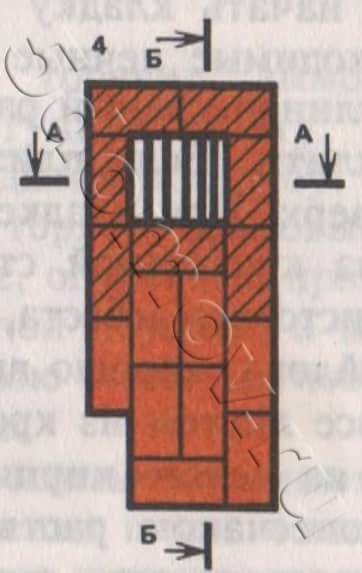
The figure below shows vertical and horizontal sections of a simple kitchen stove. Next, masonry drawings will be given in rows (ordering). From the sections and drawings of the masonry in rows, it can be seen that the masonry of a simple stove does not present any difficulties.

Sections of a simple kitchen stove: a - facade; b - section A-A (longitudinal vertical section of the furnace); c - section B-B (transverse vertical section). Designations: 1- firebox; 2 - ash chamber; 3 - grate; 4 - smoke damper; 5 - cast iron plate (flooring).
Before you start laying a simple kitchen stove, you should purchase the necessary stove appliances.
Having prepared a clay-sand mortar, they begin laying a simple stove. If the slab is placed on the foundation, then level it up. When laying a slab on a wooden floor, it is necessary to cut a sheet of roofing steel to the size of the slab. Put a layer of sheet asbestos on the floor, and in its absence - two layers of building felt, well soaked in a clay-sand mortar, cover everything with a sheet of roofing steel and nail it to the floor. Then, from a whole brick, a platform is made in two rows of masonry on a clay-sand mortar. After that, they start laying the slab from the first row strictly in order.
First row lay, observing the rules for dressing seams from selected whole bricks, as indicated in the figure below. The completed masonry is checked for squareness.

The first row of a simple kitchen oven
During laying second row arrange a blower, install blower door, which is attached to the masonry using furnace wire. Temporarily, the front blower door can be supported with bricks, which are stacked on the floor in front of the blower door. The bottom of the ash chamber is 380 × 250 mm.

Second row kitchen oven
Third row similar to the previous one, but the seams should be well bandaged.

Third row
Fourth row covers the blower door, while leaving only the opening of the ash chamber with a size of 250 × 250 mm, on which the grate is laid. If possible, laying from the fourth row is preferably made of refractory bricks, as shown in the figure below.
Laying of the fourth row. Shaded bricks are refractory. The arrows indicate the directions of movement of hot flue gases in the heating furnace.
Fifth row forms a firebox with a size of 510 × 250 mm. The brick adjacent to the grate at the back is cut off to form an inclined plane along which the fuel will roll onto the grate (see section B-B along A-A). When laying this row, you need to install a furnace door, after attaching paws from roofing steel to it with rivets.

Masonry of the fifth row of the furnace
Sixth row stack in the same way as the previous one, but the seams should be bandaged.

Masonry of the sixth row of the furnace
Seventh row placed as shown in the figure below. This row leaves the chimney under the stove, connecting the firebox to the chimney.

Seventh oven row
Eighth row perform strictly horizontally, this row closes the furnace door. A cast-iron slab is laid on the laid out eighth row with a thin layer of clay-sand mortar. Factory-made cast iron slabs have protrusions or stiffeners on the underside, which recede 15 mm from the edges of the slabs.

Eighth row oven
The internal dimensions of the masonry of the eighth row should be such that the slab freely enters it with its ribs and has a gap of at least 5 mm on all sides, designed to expand the metal when it is heated. If this is not observed, then the cast-iron plate, expanding, will destroy oven masonry. In order for the masonry to be strong, a corner steel harness is laid on the eighth row. It is desirable to cover the frame with a refractory varnish, which protects the steel from rust.
After masonry ninth row using a thin layer of clay-sand mortar, a smoke damper is installed. This row is the final one, followed by the laying of the chimney.
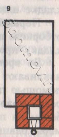
The final row of a simple kitchen oven
Cooker works as follows. Flue gases from the firebox enter under the cast-iron stove, then through the hole under the chimney through the flue valve are discharged into the chimney.
There is no cleaning hole in the stove, since you can clean the chimney through the hole under the pipe, where it is easy to put your hand through the burner cast iron plate.

Example of laying a hob
Firstly, in the stove, the furnace door is installed flush with the grate. In the stove, flue gases are constantly maintained in the chimney high temperature, as a result of which it is not necessary to lay fuel of great thickness on the grate. Secondly, with such an installation of the furnace door, the distance from the grate to the cast-iron stove will be only 280 mm, which makes it possible to quickly cook food even with low fuel consumption.
After finishing the laying of the furnace, it must be dried by opening the furnace and blower doors and the valve in the pipe.
The longer the oven dries, the stronger the masonry will be. The stove can be dried with small test fires, but after test fires, the valve in the pipe and the blower door must be left open.
After complete drying, the stove is plastered with a clay-sand mortar, followed by whitewashing.
Exterior finish is best done as follows: after laying the eighth row and installing a cast-iron slab, as well as before installing the corner steel trim, the kitchen stove is walled up on all sides in a roofing steel case (galvanized steel can be used). Pre-cut the corresponding holes according to the size of the furnace and blower doors. The case near the floor is fixed with a plinth, which is nailed around the stove. outer surface the cases are cleaned and coated with oven varnish, which withstands high temperatures well.
In front of the furnace door, a pre-furnace sheet is nailed to the floor with nails 50 mm apart from each other. If the plinth was nailed earlier, then the pre-furnace sheet must be bent onto the plinth.
Cooker with oven
The kitchen stove with oven has dimensions, mm: 1290x640x560 (without foundation, i.e. without two rows of brickwork on the floor).
For laying a stove with an oven, the following materials are needed:
- red brick - 140 pcs.;
- red clay - 60 kg;
- sand - 50 kg;
- grate - 26 × 25 cm;
- furnace door - 25 × 21 cm;
- blower door - 14 × 25 cm;
- cleaning doors 130 × 140 mm - 2 pcs.;
- cast-iron stove of five composite plates measuring 53 × 18 cm with two burners;
- smoke damper - 130 × 130 mm;
- oven - 45x31x28 cm;
- plate binding (corner 30x30x4 mm) - 4 m;
- pre-furnace sheet of roofing steel - 500 × 700 mm;
- roofing steel sheet under the slab - 1290 × 640 mm;
- building felt - 1.2 kg;
- metal box for collecting ash in the ash chamber - 350x230x100 mm.
One stove-maker can fold this oven within 3-4 hours, additionally it takes about 2 hours to bring the material and prepare the clay-sand mortar. The heat transfer of the stove during two-time cooking is about 0.8 kW (770 kcal / h). The figure below shows a general view, longitudinal and transverse sections of a stove with an oven. The following are drawings of the order of each row. Laying a stove with an oven is also not difficult and is similar to laying a simple stove, but here you have to install an oven and cleaning doors.

Cooker with oven: a - general view; b - sections A-A, B-B (vertical sections), C-C, G-D (horizontal sections). Designations: 1 - ash chamber; 2 - grate; 3 - firebox; 4 - cast iron plate; 5 - oven; 6 - smoke damper; 7 - furnace door; 8 - blower door; 9 - cleaning holes.
When laying the slab on an independent foundation, before starting work, its top is leveled with a layer of clay-sand mortar.
When installing the slab on the floor, before laying the first row, it is necessary to carry out the same work as when laying a simple kitchen stove.
masonry first row made from selected whole bricks, while strictly adhering to the rule of dressing the seams. The length of the stove should correspond to the length of five bricks, the width - to the length of 2.5 bricks. Using a cord, check the equality of the diagonals.

Laying the first row of a stove with an oven
Second row spread, strictly following the order. An ash chamber measuring 380 × 250 mm is left here, a blower door is installed and fixed, cleaning holes are left on the back wall (the width of the holes should be equal to the width of the brick, i.e. 12 cm). If possible, install cleaning doors with a size of 130 × 140 mm. At the cleaning hole extreme from the ash chamber, a brick is laid on the edge, as shown in the laying order. For better fixing of the oven in the middle of the place of its installation, put half a brick on the edge.

Laying the second row of slabs
Third row similar to the previous one, only the rule of dressing the seams should be observed.

Masonry of the third row of the slab
Fourth row covers the blower and cleaning doors. After finishing the laying of the fourth row on thin layer clay-sand mortar, an oven is installed at a pre-marked place. After that, a grate is installed. The same row of bricks installed on the edge block the chimney into the chimney.

Masonry of the fourth row of stove with oven
During laying fifth row the furnace door is installed and fixed, the brick is cut off before being installed behind the grate so that the fuel gradually rolls onto the grate during the combustion process.

Masonry of the fifth row of the slab
Sixth row similar to the fifth.

Masonry of the sixth row of the slab
Seventh row laid out in order. The resulting chimney channel from the front side is laid with the help of three bricks, as a result of which the internal size of the formed channel under the chimney will be 130 × 130 mm. In the image of this row, a steam outlet pipe with a diameter of 10 mm and a length of 160 mm is visible at the oven, which connects the oven to the ascending channel. This pipe is designed to remove steam and odor.

Masonry of the seventh row of a stove with an oven. The arrows indicate the directions of movement of hot flue gases in the heating furnace.
Eighth row
perform strictly horizontally in level. This closes the oven and the furnace door. The upper wall of the oven is coated with a layer of clay mortar up to 10-
15 mm, which will protect the oven from rapid burnout.

Laying the eighth row of a brick oven (before installing a cast-iron stove)
In this case, it is necessary that the distance between the top of the clay coating and the cast-iron plate be at least 70 mm. After that, a cast-iron slab and brickwork made of angle steel are installed on a thin layer of clay-sand mortar.

Eighth row of a brick oven (after installing a cast-iron stove)
After masonry ninth row only the laying of the vertical channel remains. The ninth row is laid according to the image below.

Ninth oven row
After masonry tenth row install a smoke damper.

Tenth oven row
Masonry eleventh row start the chimney. Further laying of the pipe is not difficult.

The final row of the furnace (does not take into account the laying of the chimney)
A stovetop with an oven works like this. From the firebox, flue gases are directed under the cast-iron stove, from where they, heating the oven from behind on both sides, fall under the oven and are directed to the hole under the chimney. Rising along the vertical channel, they enter the chimney through the smoke valve and are removed into the atmosphere.
Cooker with oven and hot water box
For laying a cooker with an oven and a hot water box measuring 1290x640 mm, the same materials are needed as for the previous stove. Additionally, you should purchase a hot water box with a size of 510x280x120 mm.
The figure below shows a general view, a horizontal section along A-A and a vertical section along B-B of the slab.

Cooker with oven and hot water box: a - general view; b - cuts. Definitions: 1 - firebox; 2 - cast iron plate; 3 - oven; 4 - hot water box; 5 - smoke damper; 6 - ash chamber; 7 - piping made of angle steel
The cooker with oven and hot water box is placed in the same order as the cooker with oven. The only difference is that after laying the third row, instead of a brick partition, a hot-water box in a case is installed on the edge between the oven and the vertical channel. The height of the hot water box must correspond to the height of four rows of flat brickwork. Otherwise, the masonry is completely similar to the masonry of a stove with an oven.
Improved Design Cooker with Oven and Hot Water Box
Cooking stoves in rural areas not only cook food for people, but also boil livestock feed, boil laundry for washing. During the firebox, a lot of steam enters the room and extraneous unpleasant odors. Because of this, the humidity in the room increases, which negatively affects its microclimate. Therefore, in order to remove foreign odor and steam in cookers, it is desirable to provide a cooking chamber, which is connected to the chimney using a ventilation duct. A ventilation valve must be installed in the ventilation duct.
Installation double door in the cooking chamber allows you to keep the food in it hot long time and thus prevent its souring.

Cooking chamber in a brick oven
The firebox and blower (ash chamber) are closed from the outside with the corresponding doors. top surface oven protect from hot gases with a layer of clay mortar 10-12 cm thick. It is advisable to lay a kitchen stove from the fourth to the ninth row of refractory bricks (especially the firebox).

An example of an ash pan cover
It is desirable to make a kitchen stove up to the ninth row of masonry from sheet steel, and to enhance its strength, after mounting the frame on a clay-sand mortar, install a trim of angular steel. Since the mass of such a plate will be more than one ton, it is installed on an independent foundation.
If it is not possible to build an independent foundation, the floor must be reinforced with additional beams that are mounted on brick columns. Instead of brick pillars, you can use pillars made of hardwood logs, reinforced concrete pillars, iron pipes with a cross section of at least 180-200 mm.
The cooker of an improved design has a “forward” stroke valve. During prolonged heating of the stove, evaporation of water in the hot water box is possible. To stop this, you need to add a little cold water and open the forward stroke valve. At the same time, flue gases from under the cast-iron stove do not go down, but immediately go into the chimney. As a result, the hot water box ceases to warm up, the evaporation of water in it stops.

Example of a "forward" stroke valve
For the convenience of cleaning the ash chamber from ash, a special box made of roofing steel with a size of 350x230x100 mm is installed in it. This prevents contamination of the room when cleaning the ash chamber from ash.
A cooker of this design has the following advantages over the previous cooker with an oven and a water box:
- during cooking, steam and foreign odors do not enter the room, which are removed into the atmosphere through the vent;
- food cooked on the stove in the cooking chamber remains hot for a long time and does not turn sour during the day;
- With the help of a “direct” stroke valve, it is possible to cook food without heating the hot water box and thereby preventing further evaporation of water in it.
The figure below shows a general view of the stove from the front, here are also drawings of cuts of the stove in the most difficult places. Masonry drawings in rows will be further, and they give a comprehensive idea of internal arrangement plates. Using the orders and drawings in rows, you can fold the slab yourself, without the help of a stove-maker.

Stove with an oven and a hot water box of an improved design: a - facade; b - sections A-A, B-B, c - cuts B-B, Y-Y, D-D, E-E. Definitions: 1 - blower door; 2 - furnace door; 3 - oven; 4 - door of the cooking chamber; 5 - smoke damper; 6 - ventilation valve; 7 - valve of the "direct" stroke; 8 - hot water box; 9 - cleaning holes; 10 - cast iron plate.
The kitchen stove with an oven and a water-heating box of an improved design has dimensions, mm: 1290x640x1330.
The following materials are required for laying:
- red brick - 250 pcs.;
- refractory brick - 80 pcs.;
- red clay - 180 kg;
- sand - 90 kg;
- furnace door - 250 × 210 mm;
- blower door - 250 × 140 mm;
- grate - 280 × 250 mm;
- oven with a size of 250x280x450 mm;
- cast iron stove with two burners - 700 × 400 mm;
- hot water box - 250x140x510 mm;
- pre-furnace sheet - 500 × 700 mm;
- steel strip size 400x250x6 mm;
- door to the cooking chamber - 750x350x5 mm;
- corner steel for strapping a plate measuring 30x30x3 mm - 4.1 m;
- steel strip for overlapping the cooking chamber with a size of 450x45x4 mm - 4 pcs.
A stove can be put together by one stove-maker within 18-20 hours, an additional 6 hours are required to prepare the solution and bring the material.
To fold the stove with the firebox on the left side, you need to consider the drawings with the help of a mirror placed with an edge on the drawing.
The kitchen stove is laid out as follows. masonry first row produced on a foundation erected to floor level. The first row defines the main dimensions of the slab. The length of the slab is equal to the length of the laying of five bricks on a clay-sand mortar, and the width is equal to the length of 2.5 bricks.

First row of improved cooker with oven and hot water box
During laying second row two cleaning doors and a blower door are installed in front. They are attached to the masonry with the help of furnace wire.

Masonry of the second row of the furnace; 1 - blower door, 9 - cleaning holes.
masonry third row produced according to the order, it is similar to the previous row. After laying the third row, a water-heating box is installed.

Masonry of the third row of the furnace; 11 - steel sheet 3 mm thick.
fireman fourth row they are laid from refractory bricks, in its absence, sorted first-class red bricks are used. The fourth row covers the cleaning holes and the blower door, forming the beginning of the hearth. After laying the fourth row, a grate and an oven are installed.

Masonry of the fourth row of the furnace
masonry fifth row presents no difficulty. The brick adjacent to the back of the grate is cut halfway to form an inclined plane.

Masonry of the fifth row of the furnace; 3 - oven.
Before masonry sixth row the furnace door is prepared, for which strip steel is attached with rivets above and below, which should be 10 cm longer on both sides of the furnace door. For greater strength, the ends of the strip steel are screwed with furnace wire, the ends of which are embedded in the masonry. The door is installed on a clay-sand mortar, having previously wrapped the frame of the furnace door with asbestos fiber.

Masonry of the sixth row
Masonry seventh row fix the base of the furnace door.

Masonry of the seventh row
Eighth row covers the water box.

Eighth row masonry
Ninth row covers the furnace door and oven. The top of the oven is protected from burning with a layer of clay mortar 10-12 mm thick. It is desirable to lay this row entirely of refractory bricks.

Ninth row masonry
After the completion of the laying of the ninth row, a cast-iron stove is installed above the firebox on a clay-sand mortar. The large burner of the stove is placed above the firebox. Next to the main plate, an additional one is placed, made of steel sheet measuring 400x200x6 mm. After that, angle steel is laid, to which the lower frame of the cooking chamber door is welded. For strength, it is advisable to tie angle steel through special holes in it with furnace wire, which is attached to the masonry.

Installation of a cast-iron stove on the ninth row; 12 - steel sheet 6 mm thick; 13 - angle steel.
Tenth row made of ordinary red brick. With right side leave a window for cleaning the channel of the "direct" stroke. Part of the bricks that overlap the slab are hewn with a pick before laying, so that in the event of a slab breakdown, it can be easily replaced.

Tenth row masonry
masonry eleventh row does not present difficulties, it is only necessary to follow the rules for dressing the seams.

Eleventh row of the furnace
Twelfth row covers the purge window.

The twelfth row of the furnace
After masonry tthirteenth row on a clay-sand solution, a “direct” stroke valve is installed.

The thirteenth row of the furnace; 6 - ventilation valve.
masonry fourteenth row must correspond to the level of the upper frame of the door to the cooking chamber. Next to the upper frame of the door to the cooking chamber, an angular steel measuring 45x45x800 mm is installed.

The fourteenth row of the furnace
Fifteenth row closes the door to the cooking chamber.

Fifteenth row of the furnace
Sixteenth row blocks the channel of the "direct" course.

Masonry of the sixteenth row of the kitchen stove
masonry seventeenth row provides a ventilation channel to remove odor and steam from the cooking chamber.

Masonry of the seventeenth row of the kitchen stove
After finishing laying eighteenth row four pieces of strip steel 4x45x500 mm in size are installed above the cooking chamber to cover the cooking chamber.

Masonry of the eighteenth row of the kitchen stove
Nineteenth row covers the cooking chamber. After the laying of this row is completed, a ventilation valve is installed.

Masonry of the nineteenth row of the kitchen stove; 6 - ventilation valve.
masonry twentieth and twenty-first rows is not difficult, only the seams should be well bandaged.

Masonry of the twentieth row of the kitchen stove

Laying the twenty-first row
masonry twentysecond row reduces the size of the chimney, it will be 130 × 130 mm.

Laying the twenty-second row
twenty third and twenty fourth ranks put in order.

23rd oven row

twenty-fourth row
After masonry twenty fifth row install a smoke damper, which is also an adjustment valve.

Laying the twenty-fifth row of the furnace; 5 - smoke damper.
Masonry twenty-sixth row start the chimney. Laying a chimney is not difficult.

Masonry of the final row (not counting the chimney)
After finishing the laying of the furnace, before coating it, the chimneys are cleaned from the fallen mortar residues and crushed stone through the cleaning holes. Holes for cleaning are then laid with brick halves on a clay-sand mortar.
When installing the cleaning doors, they are tightly closed, the leaks are covered with a clay-sand mortar.
After that, the stove can be dried in two ways: by opening the furnace and blower doors and valves or by small trial furnaces. After complete drying, the slab is plastered with a clay-sand mortar, and after the plaster has dried, a double whitewash is made. In front of the furnace door, a pre-furnace sheet is nailed to the floor.
Do-it-yourself brick cooking oven: step-by-step masonry instructions + photo
Professional ovens and craftsmen developed many models of heating and cooking stoves. Such designs are very convenient. They allow you to simultaneously heat the house and cook food.

Do you want to build a heating and cooking stove yourself? No problem! This will help you step by step instructions for the construction of two successful models: "Swedes" and a two-bell stove. Get familiar and get started.

Regardless, she needs a reliable and solid foundation. This foundation is suitable for both the Swede and the two-bell model.
The sequence for arranging the support is as follows.
First step
A swarm of a ditch about half a meter deep.

Second step
We tamp the bottom of the pit and fill it with a 15-20 cm layer of sand. Pour the sand with water and carefully tamp.
Third step
We install formwork.
Fourth step
We lay the reinforcing frame.
Fifth step
We prepare a solution from a part of cement, five parts of gravel, three parts of sifted river sand and water. Fill with such a solution about half of the free horizontal space of the pit. Let the filling dry.
sixth step
We prepare a solution from a part of cement and three parts of sand. Pour the mixture into the remaining space of the pit. top fills are carefully leveled using the rule.

seventh step
3-4 weeks after pouring, we cover the frozen foundation with a layer of roofing material.

We spread the "Swede" with the hob and oven
We are building a modified version of the Swede with an oven. Highly convenient option– you can heat the house, cook food and bake various dishes.

Let's start laying.
Posting first row. This is the most crucial stage. We put the bricks as carefully as possible, each of them is checked by a level.

In this Swede, the blower will be on the left. First we lay three-quarter bricks. To make it easier to get rid of ash in the future, we squeeze inner sides bricks towards the inner chamber. For this we use a grinder.
Install the blower door and lay out 2nd row in accordance with the order. We wrap the door with asbestos cord before installation. We use wire to fasten the door. Next, we can insert it into the previously prepared recesses in the bricks and wall it into the masonry.

Posting 3rd row ovens in order. We cut off the bricks, providing the required shape of the blower. In height, this row of masonry will coincide with the previously installed door.

Fourth row We start laying out from the right edge. Pre-install the cleaning door. When laying this row, we block the blower door. Above the ash pan you need to get square hole. To do this, appropriately chop off the bricks.

Fifth row we lay it like the fourth, but we narrow the opening of the ash pan even more.

Posting sixth row in order. On the diagram you see the shaded area. In this place, laying should be done with fireclay bricks. For greater convenience of further laying fuel on the grate, we cut off the edge of the bricks in front of the place of its installation. We lay the lattice on the fifth row.

During use of the furnace, the metal will expand under the influence of high temperatures. We act prudently and leave a 1-1.5-centimeter gap between the grate and the sixth row of masonry. In the future, we will fill it with sand.
AT seventh row install the firebox door. Then we overlap the right channel so that it turns into 3 smaller channels.

next two rows we put it similarly to the seventh. In height, the masonry will be on the same level as the furnace door. In order for the flue gases to be discharged more smoothly, we cut off the edges of the bricks laid on the partition of the right channel and the combustion chamber.


Tenth row laid out of refractory bricks. We work with the utmost care. We check the evenness of laying each element with a level. We will lay the cooking panel on this row, so there should not be any distortions and even the slightest bumps. On the same row, we close the door of the furnace compartment. On the right side there will be a couple of channels. They have a square section.

Eleventh row we can lay with simple ceramic bricks. We work in order. We lay the hob, resting it on the 10th row. We cut off the edges of the bricks of the 11th row, bordering the slab. Due to this, a 2-centimeter gap will be created between them.

Eleventh row it is also interesting that it is in the process of laying it that a frame for the damper of the brewing compartment is installed. The damper can be closed at any time, getting the oven.
In typical orders, this element is usually absent.
When laying 12th row connect the right channels. We work in order.

Spreading out 13th row, overlapping the right channel and creating a couple of new channels.

When laying 14th row install a damper to shut off the exhaust gases. Thanks to such a damper during the cooking process, it will be possible to exclude the heating of the entire structure. That is, in the summer it will be possible to safely cook food in the oven without heating the house. Otherwise, this row repeats the previously laid one.

When laying out 15th row close the damper.

In the 16th row install the door. It will play the role of a kind of hood to remove the smells of cooking food and burning.

When laying 17th row we install 2 metal support strips above the cooking chamber. Close the ventilation door.

In a traditional stove, the overlap is most often done in the form of a dome, but we do it a little differently. Let's look at the diagram.
We put 18th and 19th rows with full overlap of the brewing compartment. Previously installed strips of metal will become a reliable support for the ceiling.


When laying out 20th row we install a couple of bricks on the edge on the previously equipped ceiling. Between the end wall and these bricks, a 4-centimeter gap must be left. We install the door for cleaning and the damper of the cooking chamber.

Similarly, we put next row.

When laying 22nd row we block the doors mounted earlier. On the right we will have channels. The cross section of the middle channel above the cooking chamber will be 5 cm, the outer ones - 11 cm.

When laying 23rd row we block the channels above the cooking chamber. We put the bricks on the edge in the same way as the 20th row.

Posting 24th row like the previous one.

The next two rows are laid like a row just laid.


When laying 27th row we install 3 bricks on an edge with such a step that the distances from the walls of the stove and between adjacent bricks coincide. On the right we get a channel with a square section.

We put 28th row, diligently performing dressing masonry joints. The masonry itself is carried out similarly to the previously laid row.

AT next row we see channel 1 on the right. We lay a couple of bricks closely on the front side of this channel. We sink the bricks into the masonry by 50% of their thickness. On one side, they will rest on the bricks that we laid on the edge in the last row.

When laying 30th row close the heating section. Install the flue valve.

We put the next two rows in order. Above the thermal compartment we get 3 rows of masonry. Thanks to this, decent indicators of safety and heat capacity of the stove will be provided.


On this, the Swede is ready. You can heat your house with it, cook food and make delicious pastries.


Find out how to seal with our new article.
We build a two-bell heating and cooking stove
Such a stove will provide effective heating of 40-45 m 2 of space, which is quite an impressive indicator for a design of such a modest size. Base dimensions - 5x3.5 bricks, i.e. about 128x89 cm. Such a furnace has a height of 2.25 m.

The diagrams show all key features construction of a two-bell stove.

For greater clarity, vertical sections of the structure are shown from different angles.

We lay out a solid 1st row bricks. We check the evenness of each element with a level.
Posting second the same continuous line. It is desirable that it has rounded corners - it is more beautiful.
When laying 3rd row we proceed to the design of the blower chamber and the oven, and also set the shape of the lower hood. At the same time, we leave a 200 mm channel between the oven and the hood at the bottom. From here we begin to line the heating parts of the structure with refractory bricks.
Important! Fireclay bricks expand during heating, so between refractory and simple ceramic elements masonry should leave a gap of 0.5 mm. The gap can be made using corrugated cardboard. Pretty quickly, this material will burn out and leave the necessary clearance.
On the third row, we install a blower door and a pair of cleaning doors.
Let's start laying 4th row. The gap between the oven and the lower hood is reduced to 180 mm. we lead so that in the back left part of the place reserved for placing the oven, the bricks protrude inward. In the future, the oven box will rely on them.
When laying fifth row we reduce the gap between the wall of the hood and the oven to 12 cm. We begin to decorate the combustion chamber. It will be above the blower. We overlap part of the blower compartment with masonry and create cuts. We lay the grate on the prepared cuts so that a 5 mm gap remains between its edges and the masonry.
On the sixth row masonry, we begin to form the walls of the combustion chamber above the grate. For this we use refractory bricks. At the same time, we equip a vertical channel connecting the caps at the top and bottom. We make out the space for mounting the oven.

At the same stage, we mount the oven. We leave a 5 mm gap between the masonry and the oven box. To design the required gap, we wrap the oven box with an asbestos cord at the points of its contact with brickwork. We also leave a 20 mm free space behind the back wall of the box.
When laying seventh row we mount the door of the combustion chamber. It is best to use a glass door with the ability to control the air flow, however, an ordinary cast iron product is fine.
We stack eighth row similar to the seventh.
Posting ninth row in accordance with the ordering scheme.
When laying tenth row close the oven and firebox door.
On the 11th row form a site for hob. At the same time, the bricks laid from the front edge of the stove need to be moved outward a little.
Next row we lay it out similarly to the 11th, but we use exclusively red bricks.

At masonry of the 13th row bricks we make out the "summer" course in half a brick.
Next row lay out similarly to the 13th.
When laying out 15th row we begin to form an arch. Its height will be about 260 mm. To lay out the arch, we grind the bricks into a conical shape. The size of the wide part of such a cone will be 140 mm, and the narrow part - 45 mm.
On the 16th row cover the bottom cap. At the same stage, on the right side of our "summer" course, we install a valve, fixing it in previously prepared recesses. We cut off the bricks joining the arch at the required angle.
Next row lay out like the 16th.
When laying 18th row proceed to the formation of the cap at the top. We mount a pair of cleaning doors.
When uploading 19th row we put the bricks in the same way as the 18th row.
On the next row form a cap at the top. We install metal support corners. A row of masonry will be laid on them, blocking the opening located above the slab.
When laying 21st row we block the space above the stove, leaving only the smoke holes and the cap at the top open.
22nd row put like the previous one.

When laying 23rd row raise the cap at the top and proceed to the construction of the drying chamber. Installing a cleaning door.
On the 24th row masonry to the right of the drying compartment, we draw up a channel articulated with it. It will promote additional air circulation.
Rows 25 to 27 we put it similarly to the 24th row.
When laying 28th row we mount 2 valves in pre-created cutouts.
On the 29th row masonry we combine the hoods of the drying compartment, the cooking chamber, as well as the smoke channel.
When making 30th row cover the dryer completely.
On the 31st row we cover the entire plane, leaving open only a hole for removing smoke. This row should have an increased area. We stack exterior bricks with 40mm protrusion outward.
When laying 32nd row return the surface area to the previous value.
On the 33-34 rows We begin to lay out the chimney pipe. We bring it through the roof to the desired height. This indicator is determined individually. According to the rules, the chimney must rise above the highest point of the roof by at least 0.5 m.
You can consider options on how to do it in our new article.

Successful work!
Video - Do-it-yourself heating cooking stoves
The heating and cooking stove as a heat engineering device has a number of features that should be considered when choosing a project for construction or developing it yourself. Simply attaching the hob to some kind of stove in a place where it heats up appropriately means that the cooking will turn into torment, and the stove will not heat up as it should. Experienced stove-makers offer customers proven designs, but projects that are numerous on the Internet are not tested in practice in many cases. To choose the one suitable for building a furnace with your own hands, you need to determine how good it is.
The fact is that the intensity of heat release from a unit surface of natural solid fuel is by no means always equal to or exceeds the heat flux required for cooking through the bottom and walls of the cooking utensil. With gas or liquid fuel, the situation is different: there is enough burner of a certain design to burn the fuel arbitrarily quickly and collect the released heat in a fairly accurately limited area of space. Firewood and coal do not allow such treatment. It is for this reason that purely solid fuel cooking furnaces are not widely used; we will consider them further in passing in the general series.
Simply put, you can’t cook borscht with matches, no matter how many of them you burn one at a time. And in order to still cook, you need to make a fairly large fire out of matches, most of the heat of which will pass by the pan. That is, the ordering of the heating and cooking furnace or its drawing, if the furnace is metal, should be developed taking into account the fact that the furnace must both concentrate a certain proportion of the total heat release in the area of \u200b\u200bthe cooking stove and prevent its excessive dissipation here.
The problem is exacerbated in the warm season. In cold weather, you can simply time the rhythm of cooking to the heating cycle of the stove. But then in the summer it will be unbearably hot in the kitchen, so a good cooking stove should heat the stove properly without getting too hot, on a fuel load of at least 1/5 winter without the use of summer with winter moves and a winter-summer switch. In general, the summer operation of the furnace at the current fuel prices and their growth rates loses its meaning.

Ways of saving and concentrating thermal energy in the culinary zone of the oven are different and significantly depend on the material from which it is made. For example, if the stove is brick, it is more expedient to arrange a niche for the culinary zone, as in fig. on right. When laying fuel, the nominal thermal focus of this furnace is significantly less, i.e. a certain conditional area of attraction of the oven’s own (internal) heat flux, shifts just there and contracts, which helps to cook the weakened flow through the stove from below. And in winter, when the thermodynamic balance of the room and the street is sharply disturbed, the selection of heat for convection in the room pushes the thermal focus back into the furnace channels. At the same time, it spreads to the sides, which is required for efficient heating. There is still enough heat for cooking in excess, because. fire up the oven to the fullest.
According to this principle, the well-known ones work, (in the figure above it is she), the technical data of which are fully consistent with modern requirements. Although outwardly the Swedish stove looks like a simple stove with a heating shield attached to it, its thermal physics is much more complicated.

Double-bell
The diagram of a two-bell furnace is shown in fig. The essence of the idea is that by distributing the internal heat flow between the hoods, something can be gained for cooking and / or hot water. In principle, the second cap can be hotter than the first. Almost the limiting efficiency for brick ovens of 70-80% gives one cap.
How a two-bell heating and cooking stove is embodied in brick, one can judge its order on the trail. rice. It looks convincing enough, there are no visible flaws in theory. But, firstly, it’s very difficult for a two-burner, and you can’t squeeze out heat for 4 burners even from 2 caps. Secondly, in the structure of the furnace there is a lot of expensive fireclay, a lot of its decouplings for thermal deformations with clay bricks and metal. You can't get anywhere, the thermal regime of bell-type furnaces is more intense than channel furnaces and they cannot do without refractories. And finally, this is only a 3D project. The author does not have information about the construction of such furnaces and experience in their operation.

Two Dutch women
The Dutch oven is not suitable for the kitchen for another reason. It was invented as a purely heating system for the conditions of Central Europe, heated in winter by the North Atlantic Current. And at the end of the 16th - beginning of the 17th centuries, when the Dutch was created, there was already a shortage of fuel here: the coal deposits of the north of France had not yet been explored, and the Ruhr and Silesia are known only in pieces.

Therefore, the Dutch stove is not designed for a regular intensive firebox, but it should have, even when it has cooled down, eagerly absorb heat from the firebox and warm up quickly. This was achieved by releasing hot flue gases straight up immediately into a developed system of channels, see the diagram in fig.
There is hardly a place for a hob here and, although the efficiency of the Dutch is about 40%, it is also heat: the body of the stove literally sucks calories out of the fuel. Therefore, heating and cooking Dutch women are often made single-burner, back-up in case of a lack of gas for the stove or a culinary emergency. Half of the slab is sawn off from an unusable standard; it cracks most often from the burner above the firebox to the nearest edge.
kitchen column
One of the advantages of the Dutch oven is that it can be made very compact in plan, from 520x520 mm. The scheme of such a small (510x640 mm in plan and 2.15 m in height) and simple furnace is shown in fig. on right:

- blew;
- firebox;
- hob;
- cooking niche;
- hob arch ( flat slate 10 mm);
- bottom cleaning;
- smoke channel;
- oven;
- top cleaning;
- gate valves - a view and a gate that is not completely blocked to adjust the draft.
As can be seen from the order on the next. fig., it is also possible for an amateur to fold this stove: there are no metal embedded parts except for stove appliances in it. Although the presence of an oven may suggest that the oven is related to the Swede, this is only in appearance: the oven here does not affect the thermal physics of the furnace in any way, therefore the efficiency of the oven is “Dutch”, a little more than 40% It is suitable for winter cottage, a hunting lodge, a separate outbuilding at a camp site, a gatehouse, etc. one-room premises up to 40 sq. m.
Dutch Giant

And here in fig. - Dutch monster, two-story. Its scheme is shown in fig. on right. It is a combined, furnace and culinary part made in Swedish, but due to the developed system of channels, the thermodynamic cycle is rather Dutch and the efficiency is appropriate, 40-50% Channel stoves can be designed in this way. In principle, the more the labyrinth of channels is extended in height, the greater the efficiency of the furnace up to a certain limit of about 67%
The stove is intended for heating a house built on a small plot, but stretched upwards. With current prices and land taxes, this is quite relevant. Heated area up to 120 sq. m common; half of them are on the second floor. To heat the stove in the cold season should be coal, near firewood calorific value not enough to "fire" such a hulk.

The order of the furnace is given on the next. rice; numbers of rows of the second floor are marked with strokes. Only a very experienced stove-maker can undertake the construction of a Dutch giant, and with the indispensable, due to high altitude and the weight of the oven, subject to the following conditions:
- the furnace is built only on well-bearing soil, loam, etc.;
- the foundation for the furnace - double the power (depth) and in terms of one and a half magnitude relative to the size of the furnace;
- exposure of the poured foundation for at least 20 days to gain strength, with covering with wet burlap and then at least 40 days for shrinkage;
- the foundation is brought immediately to the level of the flooring, the screed, especially with a layer of porous insulation (expanded clay, aerated concrete) is undesirable;
- after exposure, the foundation is carefully checked for horizontality and flatness with a bubble level and a rule, if necessary, a solid one is leveled cement-sand screed or drum grinder for concrete;
- thermal insulation under the stove - felt soaked in clay milk, and on it - a sheet of roofing steel from 2 mm;
- fluffing under and in the interfloor overlap is required, it creates a horizontal power connection with the building structure, perceiving and smoothing lateral loads;
- the laying of the second floor begins only after the first floor of the furnace has completely dried, about 2 weeks in the summer;
- the dispersal of the furnace is carried out according to the full scheme, starting with 2 furnaces with newspapers or shavings;
- the height of the first floor of the furnace can be increased in accordance with the height of the ceiling of the 1st floor of the building, repeating regularly 32 and 33 rows of masonry until fluffing, but not more than 2.7 m;
- long breaks in the furnace furnace are unacceptable at any time of the year.

Finally
This article either mentions in passing or does not mention at all, bakeries and many others for cooking. They do not belong to cooking general purpose, and to special culinary or food technological. Their most common types in everyday life are already described in other articles.
Brick heating stoves, the projects of which will be presented below, can be called the best option for installation in country cottages and private houses. The functionality of this variety is such that it allows you to heat the room and feed the whole family with a delicious dinner. Equipped with an oven, a drying chamber, and sometimes a hot water box, heating and cooking stoves are able to create the maximum comfortable conditions for living in a house without centralized or autonomously arranged amenities.
This type of furnace can have various sizes and design features. Structures can be massive or compact and are usually selected desired models according to the size of the house. Therefore, it is very important to take into account not only the functional qualities of the heating structure, but also its heat transfer. When choosing a place for erecting a furnace and carrying out thermal insulation of a building, it is necessary to take into account the rules of SNiP 41-01-2003 developed by specialists, otherwise problems may arise with organizations controlling the fire safety of residential buildings.
When deciding to build a furnace on your own, you need to prepare for a laborious and quite long work, since the laying process should be measured and accurate. In the absence of experience in the skill of a stove-maker, one should clearly adhere to the tips and recommendations that will be given below, as well as carefully study and thoroughly analyze the presented ordering schemes.
Criteria for choosing the design of the heating and cooking furnace
As mentioned above, many projects have been developed for heating and cooking stoves with various operational characteristics. To this heater was effective in work and met all the requirements, it is necessary to pay attention to the following points during its construction:
- Brick dimensions. When choosing the size of the furnace, you need to take into account that its side walls give large quantity heat than the back and front surfaces.
- Given the size of the walls and their ability to give off heat, it is also necessary to foresee how the stove will be installed. To quickly and efficiently heat a room, the stove is placed sideways to it, and the cooking chamber is turned towards the kitchen room.
- The shape of the stove can be T-shaped, square, rectangular, and also with a ledge in the form of a stove or stove bench. Each of the ovens correct installation, can heat from two to four rooms.
- The heat transfer of a heating brick structure is selected depending on the area and location of the room that it must heat.
This table shows the dependence of the dimensions of the furnace (the area of \u200b\u200bits walls) relative to the area and location of the heated room:
| Room area (m²) | Furnace surface (m²) | |||
|---|---|---|---|---|
| Not corner room, inside the house | Room with one outside corner | Room with two outside corners | Hallway | |
| 8 | 1.25 | 1.95 | 2.1 | 3.4 |
| 10 | 1.5 | 2.4 | 2.6 | 4.5 |
| 15 | 2.3 | 3.4 | 3.9 | 6 |
| 20 | 3.2 | 4.2 | 4.6 | - |
| 25 | 4.6 | 6.9 | 7.8 | - |
- For small-sized rooms, massive heating structures should not be chosen, since a compact stove can also heat them. To heat up a massive furnace, a large amount of fuel is required, and such a design will warm up for a long time.
- The efficiency of the furnace will directly depend on how insulated the building is. In a well-insulated house, a small stove will be enough, since the walls, floor and ceiling will reliably keep the heat generated by it inside the premises and will reliably protect it from the cold trying to penetrate from the outside.
Only having provided for all these factors, they make a choice in favor of one or another model of a heating and cooking stove.
Models of heating and cooking stoves
The design of multifunctional models of stoves can be different - both with a complex internal configuration of chimney channels, and very simple. If the laying of the furnace will be carried out by a novice master, then you should not immediately "swing" at complex and incomprehensible structures. Before getting down to work, you need to try to figure out how the heated air, together with the products of combustion, will pass towards the chimney, since during masonry it will be necessary to follow all the configurations of the rows in order to bring the exhaust channels correctly.
The most popular models that have a construction available for masonry are “Swede”, “Dutch” and a cooking oven. In addition to them, there are heating facilities, which are called by the names of their developers. So, you can find the orders of the heating and cooking stoves of Proskurin, Bykov, Porfiriev, Kuznetsov, Podgorodnikov and other craftsmen.
You might be interested in information about how .
Furnaces can be divided according to their shape. So, they can have the following configuration.
- A T-shaped heating and cooking stove is usually massive and can be installed in the middle of a large room, dividing it into different zones. Another option - it is built into the walls between the three rooms, fully heating them.

If the house is of medium size and does not have other heating besides the stove, then the T-shaped model will be the best option for it, since you do not have to install and heat several stoves.
- A narrow oven with a protruding hob is less functional, but it takes up much less space. This design is able to fully heat two rooms, and therefore is perfect for country house, especially, due to its simple design, even a novice stove-maker can probably fold it. The compactness of the structure allows it to be built into the wall between the living room and the kitchen.

So the stove will be able to not only heat two rooms at the same time, but also cook dinner. Such a stove is indispensable for a small country house, as it can be heated with dry branches or deadwood, and this goodness can always be found in the nearest forest plantation.
- This oven model has the average size and aesthetic appearance. Although it is not as massive as the "Russian", it is equipped with all the features characteristic of the latter. A chamber is built inside the structure, in which you can not only cook stews, but also bake fragrant homemade bread. A hob is installed in front of the entrance to the inner chamber.

Using it and the flame chamber, you can cook several dishes at once. Above the hob there is a chamber for drying vegetables and fruits, and it can also be used to store ready-made meals that need to be kept warm.
The glass door of the firebox is large enough, so the stove, if desired, can also be used as a fireplace. A lounger, heated on both sides, can serve as an excellent warm bed.
It is good to install such a stove between two rooms that need to be heated. This model - good option for country house if it is used for living most of the year.
- This model may well be called a fireplace stove, and this version of the heating structure is usually installed in the middle of the house, only then dividing it into separate rooms. The fireplace insert goes into the living room or bedroom, the hob - into the kitchen, and the back wall is quite capable of heating another small room. Thus, the whole house will be filled with dry and pleasant warmth emanating from the walls of a brick stove.

Most often, heating and cooking stoves have a “winter” and “summer” course in their design, which allows you to use only the stove and oven in the warm season, without heating the entire massive structure. This feature is convenient in that you do not have to endure the heat from a heated stove when it is summer weather outside, as well as the ability to save on fuel.
The location of the stove in the house
The location of the planned location of the stove plays an important role in ensuring high-quality heating at home, as well as in the practicality and safety of its use. Tei, however, there are other criteria that should be considered when choosing a place to install it.

- Most often in small house the stove is installed at the crossroads of the walls dividing the building into separate rooms, as shown in the diagram above.
- If the oven is located near the entrance, it will create a kind of thermal curtain from the cold air coming from the street.
- The firebox door, facing the hallway or kitchen, will make it possible to easily deliver fuel to it, which means that less garbage will enter the living rooms.
- All walls of the heating structure must be free, that is, not forced by anything, and should not adjoin closely to the wall. This is explained by the fact that for the purposes of safety and proper control, the laying of the structure requires periodic inspection, preventive maintenance and the release of the treatment chambers from the accumulated burning.
- The foundation of the furnace must be reliable and not connected with the main foundation of the house itself. The reason is the different shrinkage rate of the base - it is impossible for one to “pull” the other. These factors must be provided for for safety reasons, since if deformation of the base of the furnace occurs, then cracks may appear in the seams between the bricks, through which it can penetrate into the premises carbon monoxide dangerous not only for health, but also for human life.
- The design is installed so that the chimney passes between the floor beams, which, in turn, must be insulated from it with heat-resistant material.
- To comply with fire safety, it is necessary to place a platform in front of the fireboxes, covered with heat-resistant material - this can be sheet metal or ceramic tiles. For this site, space must also be provided in advance.
The main elements of the furnace design
When starting to analyze the orders, it is necessary to have an idea about the main elements of the furnace design, about their purpose, since with such information the internal configuration of channels and chambers will be more understandable.

- The furnace or fuel chamber can be called the "heart" of the furnace. It is filled with fuel, after the combustion of which the heat fills all the internal channels of the structure, heating the entire structure.
The firebox is separated from the lower blower chamber by a cast-iron grate through which blowing is carried out, providing draft for heated air and combustion products. The combustion chamber has an opening in its ceiling part, connecting it with the channels through which the smoke is directed to the chimney.
- The blower chamber or ashpit is a regulator of air supply to the furnace and at the same time a collector for ash from the fuel burned in the furnace. This part of the stove must be cleaned periodically to avoid back draft, which will cause smoke to enter the living quarters.
- Cleaning chambers with cast iron doors are connected to the internal chimney channels and are designed for their regular cleaning. The soot that has settled on the walls from rising smoke eventually crumbles into chambers that need to be cleaned periodically, otherwise the draft in the chimney will be reduced.
- Chimney channels passing inside the structure in different models have a different configuration. They can run vertically and horizontally, covering the entire structure. The heated air, passing through them, gives off heat to the walls of the furnace, which, in turn, radiate it into the room.

Each stove has its own system of internal channels for moving smoke and hot air
- Metal and cast iron elements, such as a hot water tank, a hob and an oven, are built into the masonry of the stove according to the scheme and are intended for cooking and heating water.
- If the design of the stove includes a fireplace insert, then a cast-iron grate must be installed in front of it to prevent burning firewood from falling out of the hearth.
Materials for the construction of the furnace
One of the most important issues is the purchase of high-quality materials for the construction of the furnace, since the durability and reliability of the structure will depend on them. So, for the construction of a heating and cooking furnace, you will need:

- Heat-resistant solid red brick. Its quantity depends on the specific model. When buying a material, you need to carefully examine it - there should be no chips on the edges of the brick, and serious depressions on the surfaces. Transportation of this material must be carried out very carefully, as it is quite fragile.

Chamotte brick - for laying out heat-resistant sections of the furnace
- Fireclay bricks are used for lining the combustion chamber, as they withstand temperatures of 1400 ÷ 1500 ° C. When warmed up, this material retains a high temperature for a long time due to its density, which means that the oven, thanks to it, will stay hot longer.

Particular attention to quality masonry mortar
- For laying bricks, you need to choose correct composition solution. Or rather, they are usually used even several - for different departments of the structure. And yet the main material for bonding bricks is a clay-sand mixture. The fireclay walls of the firebox are placed on the same solution, only together in it quartz sand fireclay is added. For the section of the chimney pipe located on the street, it is applied cement mortar. For laying the first two rows of the furnace design, some craftsmen prefer to use a lime mixture.
The choice of masonry mortar requires a special approach.
Choosing the right solution and composing it is a whole science. Some of the recommendations of the masters are set out in a special article on our portal that talks specifically about.

- Cast iron elements such as doors, latches, stove, grate, etc., must be selected not only for their quality, but sometimes also for decorative design, as they must match the overall exterior of the oven.
- Metal elements - an oven and a hot water tank, will be necessary if they are planned in the design.
- You will need annealed steel wire with a diameter of 4 ÷ 5 mm - to fix the cast iron elements.
- Need asbestos sheet thickness 5 mm or asbestos cord. They are used to create a thermal gap between brick and cast iron (steel) elements.
Now that there is clarity with preliminary planning and the necessary materials, we can proceed to the study of ordering schemes. Next, we will consider the construction of two available in design, functional and compact models which will certainly appeal to novice stove-makers.
Stove-fireplace "Swede" A. Ryazankin
This is a heating and cooking stove-fireplace, one of the many variations of the "Swede", which is quite popular among Russian stove-makers and householders. This design has gained its popularity not only due to a simple ordering scheme, but also because of the rapid heating of surfaces, and hence the heat transfer to the premises. In addition, the stove is equipped not only with a hob and an oven, but also a fireplace function is included in its design. The successful arrangement of all elements allows you to install it so that it will be effective for heating two rooms.

Heating and cooking "Swedish" stove-fireplace designed by Ryazankin
Another advantage of this model is its compactness, which allows it to be placed both in a small room and in a spacious room.

This “Swede” model has a base size of 1020 × 890 mm and a height of 2170 mm, excluding the height of the chimney. In this case, it must be taken into account that one side of the structure will be wider due to the protrusion of the fireplace portal by 130 mm.
The foundation for the installation of the furnace must be arranged larger than its base, and the sides of the square slab to be poured must be 1120 x 1120 mm.

This stove is heated with wood and has a capacity of 3000 kcal/h. It is able to effectively heat 32-35 m² of area, which is not bad at all for such a small structure.
What materials will be required?
Table necessary materials for the construction of a fireplace stove:
| Material name | Size (mm) | Quantity (piece) |
|---|---|---|
| 250×120×60 | 714 | |
| Blower door | 140×140 | 1 |
| Door for combustion chamber | 210×250 | 1 |
| Door for cleaning chambers | 140×140 | 8 |
| Oven | 450×360×300 | 1 |
| 410×710 | 1 | |
| Grate | 200×300 | 1 |
| Chimney damper | 130×250 | 3 |
| steel corner | 50×50×5×1020 | 2 |
| steel strip | 50×5×920 | 3 |
| steel strip | 50×5×530 | 2 |
| steel strip | 50×5×480 | 2 |
| Fireplace grate, you can make it yourself from reinforcing bars. | 110×700 | 1 |
| Metal sheet for flooring in front of the firebox | 500×700 | 1 |
| 5 mm thick | 1 |
Table from the ordinal masonry of the heating and cooking "Swede" with a fireplace designed by Ryazankin
| Scheme-ordering | |
|---|---|
 | In order to have a better idea of the masonry layout of this kiln model, the project will be considered in the form of a drawing and in 3D projections, with detailed description each of the rows. |
 | The first row consists of 34 bricks and is the basis of the whole structure, so the brick covers it completely, that is, it forms a continuous surface. The installation of this series is carried out on waterproofing material- roofing felt, laid in 2-3 layers. Since the first row sets the reliability of the entire structure, it must be brought out perfectly even, having previously verified and marked the corners on the roofing material using a square, ruler and chalk. Further, keeping the scheme at hand and observing the location of the bricks, the laying is done first dry, and then on the mortar. |
 | The second row consists of 30 ½ bricks and, like the first, has a solid plane. From the side of the future fireplace, metal brackets are fixed to the brick, made from pieces of reinforcement, on which the fireplace grate will be welded. If the grille already has brackets, then it is completely fixed on the brickwork. |
 | The third row consists of 19 bricks. At this stage, the walls of the furnaces and chimney channels are laid. Between the place where the oven will be located and the emerging vertical channel, you must leave at least 170 mm. When laying the walls, openings are left for the installation of blower and cleaning doors. Then the doors are installed in place and secured with wire twists, which are embedded in the seams between the rows. Since only the next row can finally fix the wire, the doors are temporarily supported by stacks of bricks. |
 | The fourth row is laid out from 18 bricks. The doors of the blower and cleaning chambers are finally fixed on it. Due to the fact that wire is embedded in the seams between the third and fourth row, the seams can be two to three millimeters wider. |
 | The fifth row consists of 24 bricks. Above the blower chamber, bricks are laid with grooves cut into them, into which the grate will be laid. In addition, a place is being prepared for the installation of an oven. The front bricks, in the place where the metal box will be installed, are cut off, since their height should be 25 mm. For laying out the walls of the furnace, it is recommended to use heat-resistant fireclay bricks. |
 | Before installing the oven box in place, it is wrapped or wrapped with asbestos to create a gap around it for thermal expansion when heated. |
 | On the fifth row, a grate 200 × 300 mm and an oven box 450 × 360 × 300 mm are installed. |
 | The sixth row is laid out from 19½ bricks. A combustion chamber is formed on it, on the right and rear wall of which the brick is installed on the side and cut off to a height of 75 mm. On the same row, the passage between the oven chamber and the vertical channel is blocked. When laying out the back wall of the fireplace, the bricks move forward by 35 mm and are squeezed, forming a smooth transition from the extended row to a flat wall. |
 | On the sixth row, the furnace door (210 × 250 mm) is installed, which is pre-wrapped or lined with asbestos, which creates a gap for the thermal expansion of the metal when it is heated. The furnace door is also fixed with wire twists, which will be embedded in the next seam between the rows. |
 | Scheme-ordering from 7 to 12 row, which will help to better consider the configuration of the masonry. |
 | The seventh row, consisting of 20 bricks, is laid out according to the scheme. The bricks that form the right and rear wall of the combustion chamber are installed on the side. The bricks on the back wall of the fireplace insert in this row also move forward 35 mm and are cut obliquely to form a single inclined plane. The front part of the fireplace insert is covered with a metal strip 50 × 530 × 5 mm in size - it will become the basis for the laying of subsequent rows. This element can be laid flat or semi-arched - for this, the strip is given the desired shape in advance. |
 | The eighth row consists of 18 bricks. The bricks on the back wall of the fireplace are pushed forward by 35 mm and compared, by cutting them obliquely, with the lower rows. The back wall of the fireplace should be tilted forward, for a smooth flow of smoke into the chimney when wood is burned in the firebox. |
 | The ninth row consists of 20 bricks. When it is laid out, the fuel chamber door overlaps. The brick that forms the back wall of the firebox is cut obliquely. The brick of the back wall of the fireplace is pushed forward by 20 mm and is squeezed from below in such a way that an even slope without protrusions is formed. The oven box is covered in front with two steel strips, 50 × 5 × 480 mm in size. |
 | 10th row - the front of the oven is covered with a brick. Brick is laid on metal strips. The combustion chamber and the space of the oven are combined into one common one. In the upper part of the bricks framing both chambers, a cut is made for laying the hob. A place is made for installing the door on the cleaning chamber at the top of the fireplace. For laying this row, 17 ½ bricks are used. |
 | On the 10th row, a two-burner hob 410 × 710 mm in size is installed on the prepared place, then a cleaning door 140 × 140 mm and a metal corner 50 × 50 × 5 × 1020 mm are mounted, which will strengthen the front of the cooking chamber. The cast-iron hob is mounted on the asbestos laid in the cutout on the upper bricks. |
 | The 11th row is derived from 18½ bricks. At this stage, the walls of the cooking chamber begin to form. Bricks laid on the right must cover the resulting gap of 210 mm between the hob and the right wall. The brick laid above the fireplace insert is extended into the chamber by 40 mm and cut from below at an angle, continuing to form the inclined shape of the back wall of the fireplace. |
 | The 12th row is laid out from 18 bricks. It covers the door of the cleaning chamber. The bricks of the front wall of the firebox of the fireplace are shifted inward by 40 mm and are hemmed obliquely. |
 | In this drawing, you can clearly see the configuration of the brickwork from the 13th to the 24th row. Moreover, the diagram shows even the direction of movement air masses through flue ducts. |
 | The 13th row consists of 19 bricks. The elements of the front wall of the fireplace are pushed forward, inside the firebox, by 40 mm and are hemmed obliquely, compared with the lower rows. In addition, the walls of the hob and chimney channels continue to rise. |
 | 14th row. A shelf begins to form above the fireplace insert. To do this, the bricks laid in this row are pushed forward and to the side by 30 mm. It will turn out, as it were, a row of bricks hanging over the firebox. A row will require 19 bricks. |
 | The 15th row is laid out from 20½ bricks. A mantelpiece continues to be laid out on it by pushing a row of bricks forward by 30 mm. The removal of the walls of the cooking chamber is completed. |
 | The 16th row consists of 15 ½ bricks. After laying them, the front part of the "ceiling" of the hob is reinforced with an installed steel corner, 50 × 50 × 5 × 1020 mm in size, and the middle and rear parts of the "ceiling" of the chamber are covered with steel strips measuring 50 × 5 × 920 mm. All metal elements will become the basis for blocking the chamber with bricks. The remaining bricks are laid according to the scheme. |
 | 17th row. A complete overlap of the cooking chamber is carried out with the help of 26 bricks. Only two openings of the chimney channels are left. |
 | 18th row. The second continuous row is being laid, which consists of 30 bricks. |
 | The 19th row is laid out from 19 ½ bricks. At this stage, the upper gas outlet channels and cleaning chambers are being formed, on which the doors are installed. The jumper between the fireplace chimney and the vertical channel is shifted 30 mm to the left. At the same time, the lower and upper left faces of the brick are cut off. |
 | 20th row. The jumper, as in the 19th row, moves to the left by another 30 mm, and the brick of the jumper is also cut obliquely. This row will require 22½ bricks. |
 | 21st row. The doors of the cleaning chambers installed on top of the cooking niche are closed, and a door is installed on another cleaning channel, above the fireplace insert. The chimney flue opening is narrowed by another 30 mm. The main channel of the chimney is blocked to the size of ¾ bricks, and a “shelf” is formed inside the channel. A row will require 22½ bricks. |
 | 22nd row. In the place where the “shelf” is formed, a place is prepared for the cleaning door at the base of the vertical channel. The jumper between the two channels located above the fireplace is still shifted to the left by 30 mm. After the row is folded, a door is installed on the channel. For a row, you need to prepare 22 bricks. |
 | The 23rd row is laid out from 23 bricks. The jumper between the channels is still shifted to the left. The cleaning door above the fireplace is blocked with a brick. |
 | 24th row. A place is being prepared for the installation of a chimney valve. To do this, special grooves are cut out in the bricks framing the chimney opening. Then, a valve structure with a size of 130 × 250 mm is installed on the clay solution. For laying this row, 22 bricks are required. |
 | 25th row. A shelf is arranged at the base of the chimney channel, a place is being prepared for the installation of another valve - for the cooking chamber. Then, also on the clay mortar, the valve itself is mounted with a size of 130 × 250 mm. A row will require 24 bricks. |
 | The final diagram showing the brickwork configuration from rows 25 to 33. |
 | 26th row. At this stage, the holes of the chimney vertical channels are combined in pairs. The opening of the fireplace channel, due to cutting the upper edge of the brick at 45 degrees, is shifted to the center. A place is being prepared for installing the cleaning chamber door for the main vertical channel. The main chimney channel is connected to the system of all gas outlets of the furnace. After the row is laid out, a chimney cleaning door is installed. For a row, you need to prepare 21 bricks. |
 | 27th row. Continuation of the displacement of the fireplace channel to the center of the structure. In this row, the middle brick, located on the opposite side of the main chimney channel, is cut obliquely, and the two bricks shifted to the channel are cut at an angle of 45 degrees from below. For a row, 21 bricks will be needed. |
 | 28th row. There is a union of the chimneys of the fireplace and stove, and the fireplace channel continues to shift towards the center. For a row, 20 bricks are used. |
 | 29th row. The design of the furnace is completely covered, with the exception of the chimney opening, which continues to shift towards the center. Brickwork is shifted beyond the perimeter of the furnace by 25 mm. For masonry, 34 ½ bricks are required. |
 | 30th row. This row, like the previous one, is shifted by 25 mm, but already in relation to the underlying bricks. The size of the chimney opening is reduced to 130×260 mm. A row will require 36 bricks. |
 | 31st row. The perimeter of the structure returns to the main size of the furnace - this is achieved by shifting the brick deep by 50 mm. Laying out a row, in it, for installing a valve on the chimney, special cutouts are arranged in the bricks framing it. Then, the valve itself is mounted in this groove, having a size of 130 × 250 mm. For a row, 27 bricks will be needed. |
 | 32nd row. The first row is formed, that is, the base of the overhead chimney. This will require 5 bricks. |
 | 33rd row of the furnace or the second row of pipe laying. It will also require 5 bricks. Well, the design of the pipe itself is already laid out above. |
These diagrams show sections of the furnace.

Sections - scheme 1
The first shows the direction of the smoke from the combustion chamber of the furnace through the chimney channels towards the chimney.
The first diagram clearly shows how the valves are installed on the vertical channels.

Section - scheme 2
The second figure shows the removal of smoke from the fireplace insert into the main chimney, with the dampers open.
Heating and cooking "Swedish" oven
This Swedish model is even more compact than the previous one, since it does not have a fireplace function. This means that its scheme is simpler, since there is no chimney channel from the fireplace insert.

Compact heating and cooking "Swede"
The size of this structure is 1020×885×2030 mm, and the power is 2750 kcal/h, which is enough to heat 30 m². It can be seen that the characteristic is somewhat lower than that of the model considered earlier. Nevertheless, even such a stove is quite capable of heating two adjacent rooms.
This stove has a convenient arrangement of the main elements, thanks to which it can be placed in the wall between two rooms. For example, the furnace part with a hob and an oven unfolds into the kitchen, and a large heated surface of the rear wall of the stove into the living area. By arranging the structure in this way, that is, in the thickness of the wall, you can additionally win space, so the stove will look more compact.
It should be noted that this project was drawn up subject to certain conditions, having learned about which, many will make a choice in favor of just such a design.
- The stove was originally designed to heat a country house built of silicate blocks and having a size of 4000 × 7000 mm.
- This heater is designed to use wood, but it is quite possible to use other types of fuel.
- In this design, only the inner lining of the furnace and adjacent objects is provided. Since the furnace will be built from quality material, exterior finish walls are not planned. Refractory bricks are hidden inside the structure so that they do not disturb the harmonious façade appearance.
- The walls of this model must be thick, and laying bricks on the side (on spoons) is not allowed.
- A drying chamber must be mandatory in this model.
The result of this development, taking into account the specified criteria, was the furnace, the order of which will be discussed below.
Building materials
First you need to decide what materials and in what quantity will be required for its construction.
Table of necessary materials for the construction of a heating and cooking "Swede":
| Material name | Size (mm) | Quantity (piece) |
|---|---|---|
| Red brick (excluding pipe height) | 250×120×60 | 551 |
| Refractory fireclay bricks Sh-8 | 250×124×65 | 31 |
| Blower door | 140×250 | 1 |
| Door for combustion chamber | 210×250 | 1 |
| Door for cleaning chambers | 140×140 | 3 |
| Oven | 450×250×290 | 1 |
| Double burner cast iron stove | 410×710 | 1 |
| Grate | 200×300 | 1 |
| Chimney damper | 130×250 | 1 |
| Steam damper | 130×130 | 1 |
| steel corner | 45×45×5×1020 | 1 |
| steel strip | 45×45×5×700 | 1 |
| steel strip | 45×45×5×905 | 5 |
| steel strip | 50×5×650 | 2 |
| Shelf for dryer | 190×340 | 1 |
| Metal sheet for drying chambers | 800×905 | 1 |
| Pre-furnace metal sheet | 500×700 | 1 |
| Asbestos sheet or rope for laying between metal elements and brickwork. | 5 mm thick | 1 |
Ordering the heating and cooking stove - "Swedes"

| Scheme - ordering | Brief description of the operation to be performed |
|---|---|
 | The first row, consisting of 28 red bricks, is traditionally laid out in a solid plane. It is very important to observe the ideal horizontal laying and right angles of the base. |
 | The second row is also solid, but the brick laying configuration differs from the bottom one, since the seams between the bricks of the first row must overlap with the solid surface of the second brick (in ligation). This row will require 28½ red bricks. |
 | Third row. The blower chamber and the lower heating chamber, as well as vertical channels, begin to form. On the same row, three doors are installed on the cleaning chambers, as well as on the blower. In the internal structure of the row, two solid bricks and two three-quarter bricks are installed on the edge. In addition, a quarter of fireclay bricks is installed at the entrance to the first chimney channel. For a row, 19 red and ¼ fireclay bricks are used. |
 | In the fourth row, all the chambers mentioned above continue to form. Both in the second and third row, and in the fourth, the vertical channels are combined. For a row, prepare 14½ red and ½ fireclay bricks. |
 | Fifth row. At this stage, all the doors installed at the entrances to the channels and chambers are blocked. The bottom of the combustion chamber is laid out with fireclay bricks. In the middle opening of the bottom part of the furnace, a step is cut out in refractory bricks, on which the grate will be laid. For a row, 16 red and 8 refractory bricks are used. |
 | Sixth row. Installed furnace door, which is temporarily supported by loose bricks, as well as an oven box wrapped in asbestos. The inner walls of the fuel chamber and the base for the oven are laid out of fireclay bricks. In this case, it must be taken into account that the wall of refractory bricks erected between the fuel chamber and the oven should be a quarter of a brick. On the same row, the second and third vertical channels are separated from each other. For a row, 13 red and 6½ fireclay bricks are used. |
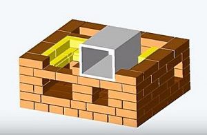 | This figure shows the same sixth row - oven installation. When mounting it, we must not forget about the thermal gap for the expansion of the metal when it is heated - it can provide a layer of asbestos. The box can be wrapped with asbestos rope or overlaid with sheets cut to size. |
 | Seventh row. The chambers continue to be formed from two walls - an internal fire-resistant one and an external one made of red brick laid flat. For a row, 13 red and 4 fireclay bricks will be needed. |
 | Eighth row. At this stage, the first chimney channel is blocked. The rest of the masonry is carried out according to the scheme using 13 red and 5 fireclay bricks. |
 | Ninth row. The furnace door is closed, and the rest of the masonry is carried out according to plan. For a row, 13½ red and 5 fireclay bricks are used. |
 | Tenth row. The oven is covered with brickwork. The top row of the wall between the firebox and the oven is not laid out. In the inner walls, lined with fireclay bricks, framing the upper space, cuts of 10 mm are made, intended for mounting the hob. For a row, you will need 15 red and 4½ fireclay bricks. |
 | Further, on the same row, the hob is laid. Under it, you should also make a gasket from an asbestos rope. The plate must be in the same plane with the walls of the structure. On the front wall, in front of the hob, a metal corner is laid, which will protect the brick edge from chips and fasten the top row. |
 | 11th row. The walls of the cooking chamber begin to form. The gap between the slab and the wall of the structure on the right side is bricked up. This row will require 16½ red bricks. |
 | 12th row - masonry is carried out according to the scheme, and 15 red bricks are used for it. |
 | The 13th and 14th rows are laid out of red brick according to the scheme indicated in the order, taking into account the laying in the dressing. For work you will need: for the 13th row -15½, and for the 14th row 14½ bricks. |
 | The 15th and 16th rows are also placed according to the same pattern. For the 15th row you need 15½, and for the 16th row - 14½ red bricks. |
 | 16th row. After the row is removed, the cooking chamber is covered with three metal corners (45 × 45 × 905 mm), which are mounted in the middle and end of the chamber, and its edge is reinforced with a corner having dimensional parameters of 45 × 45 × 700 mm. In the middle of the opening, two corners are laid, vertically arranged shelves to each other. Thus, a reliable basis for blocking the chamber with a brick is obtained. |
 | The 17th row is laid out from 25½ bricks. It covers the space of the camera. At the same time, an exhaust hole from the cooking chamber is formed in the surface, the size of which is half a brick. In addition to it, the walls of the channels located in the rear of the furnace are laid out. |
 | The 18th row is laid solid. Only chimneys and exhaust channel. The next step, a corner is mounted on the front edge of the ceiling, having dimensions of 45 × 45 × 905 mm. The overlap, reinforced on both sides, will securely hold two rows of brickwork. This row will require 25 red bricks. |
 | 19th row. At this stage, two drying chambers are formed - large and small, as well as a ventilation channel that will remove steam from the cooking chamber. For laying this row, you need to prepare 16 red bricks. |
 | 20 row is laid out according to the scheme of 16 red bricks. |
 | The 21st and 22nd rows also have a similar configuration, in dressing. For the 21st row, 16½ are used, and for the 22nd row, 16 red bricks. On the 22nd row, the small drying chamber is covered in front with a metal plate 190 × 340 mm. |
 | 23rd row. The walls of the drying chambers and smoke ducts continue to form. A cutout is made above the ventilation duct in the brick - a seat for a valve that will regulate the temperature of the cooking chamber. Then, a 140 × 140 mm valve is installed in the prepared cutout. To work, you need 17 red bricks. |
 | 24th row. The work is proceeding according to the scheme - the ventilation valve is closed, the first and second chimney channels are combined. For laying this row, it is necessary to prepare 15½ bricks. |
 | 25th row. At this stage, the ventilation and three vertical chimney channels are combined into one channel. A row will require 15½ red bricks. |
 | The 26th row is laid according to the pattern of 16½ red bricks. |
 | Further, on the 26th row, a basis is made for the subsequent overlap of the drying chambers. For this, a metal corner is used, 45 × 45 × 905 in size and two steel strips 50 × 5 × 650 mm. The corner is mounted on the edge of the drying chambers and creates a rigid base for their overlapping with a metal sheet and a row of bricks. |
 | Then, on top of the installed jumpers, it is laid a metal sheet, having a size of 800 × 905 mm, which covers the entire surface of the furnace section, leaving only the third vertical chimney channel free. |
 | 27th row. On this row, the metal sheet is covered with solid brickwork, which protrudes 25 mm beyond the perimeter of the furnace. In the left corner, the opening of the chimney channel remains free. For overlapping, 32 red bricks are required. |
 | The 28th is the second row of complete overlapping of the drying chambers with a hole for the chimney. It is laid with a protrusion beyond the perimeter of the previous row by 25 mm. To lay it, you will need 37 red bricks. |
 | The 29th row consists of 26½ red bricks, which are laid indented from the previous row to the center by 50 mm. That is, it turns out a rectangle of the same size around the perimeter as the entire main structure of the furnace. |
 | The 30th row of the design is the first row of a mounted chimney. It consists of 5 red bricks. In the upper part of this row, cuts are made with a depth of 10 mm - this will be a seat for the main chimney valve, which has a size of 250 × 130 mm. When the place is ready, the valve structure is mounted on the clay mortar. |
 | 31st row - the second row of the pipe closes the installed valve. The row also consists of 5 bricks. Next - the chimney pipe is laid out upward. |
The diagram below shows the flow of heated air through vertical flue ducts, through which the entire brick construction including the oven.