Chimney lining. Mortar for laying a brick pipe Parameters of brick chimneys
The purpose of the chimney- not only increase traction, but also raise gases as high as possible above the ground. The higher the chimney, the stronger the draft in the furnace. And I would say that strong traction is not needed in furnaces for housing and communal purposes, they need normal traction, and even from the best furnace it takes 75% of the heat generated by fuel to the street.
A pipe standing on a furnace is called a pipe, a pipe standing separately on the ground is called a root pipe. There are pipes located on the main walls brick buildings, they are close to indigenous. But there are rude ones that do not belong to either the built-in or the indigenous ones, because they are located in the attic of rural houses on special elevations - platforms. From the furnace to such a pipe, a horizontal gas flue - a hog - is brought on weight.
Packed pipe starts immediately at the top of the furnace ceiling. Over its entire height, the necessary overlaps are laid out in three places. The first laps (fire cut) are made in the ceiling opening, they expand the pipe to right size. In the old days, the pipe was used to judge the character of the owner, his position, his penchant for the architectural decoration of the house. All pipes were made only of bricks. Now, however, asbestos-cement and iron pipes are in vogue, and inside they are overgrown with resin emitted by combustible fuel, ignite, and asbestos-cement pipes burst.
brick pipe adds beauty to the home. You can lay out the pipe along the edge of the edged board, rail or twine, fixed from the ceiling to the roof in a vertical position. Almost all chimneys stand with two or three walls on the walls of the furnace, which have to withstand very heavy loads, so only high-quality bricks should be used when laying.
The most reliable chimney- from red well-annealed brick, built on lime mortar. It is warm and fluffy. These pipes are durable. The seams in the pipes allow air to pass through, so they breathe and do not “sweat” inside. Do not lay the pipe on a solution consisting only of cement and sand. Such a solution is very dense, does not allow air to pass through and “sweats”, therefore streaks are formed, which, mixing with soot, pass through the seams of the furnace walls and not only spoil the whitewash with dirty spots, but also emit bad smell. In the absence of lime, clay diluted to the state of liquid sour cream can be added to the solution. The solution will become looser and there will be no soot streaks.
When they say: “It's time to close the pipe”, referring to valves or views, this indicates that the pipe starts above these devices. The hottest air, heat, comes to them from the firebox. It, like fire, burns chemicals released during the combustion of fuel. The pipe in which the draft is formed removes all odors from the stove and partially from the room, so they cannot and should not get from the stove into the room.
You can not put a chimney over a half-empty place. In such places, in Russian stoves, fireplaces, metal, reinforced concrete are laid or an arched ceiling is made. On stoves folded on edge with a wall thickness of 65 mm with good dressing kiln masonry you can put a pipe on top. It is impossible to narrow the gas ducts of the pipe, since the amount of soot deposited in the pipe and gas ducts depends on them. When the fuel ignites, a lot of smoke is released, and the flue of the pipe must be wide enough to quickly lead it to the street. Above ceiling(starting from cutting) the pipe is most often laid on a complex mortar, and it is harder than clay mortar, the seams from it are thicker, so it is better to lay the pipe from cutting to the roof all the same on clay mortar. In each house, the pipe has its own height.
How to find out how much brick will go to the pipe. To do this, you need to measure the height of the future pipe from the top of the furnace plus 30 cm above the roof. The average row height is 7 cm. For example, the height of your pipe is 2 m 35 cm. And how many rows does it have? The height of the pipe is divided by the height of the row, 34 rows are obtained. 4 bricks are laid in one row of pipes. We multiply these 4 bricks by 34 rows, we get 136 bricks per pipe. But in three places of the pipe, more extensions must be made, which also require bricks, an average of 70 pieces. So, 210 bricks will go to such a pipe. If in one row of pipes not 4, but 5 bricks are laid, then according to these calculations, 240-270 bricks will go to such a pipe.
Cutting a pipe in a ceiling opening
Before laying the cutting (expansion) of the pipe, you need to check the horizontal position of the laying, determine how many rows are left to the ceiling, take into account the height of the cutting, draft, for example, a log house. The figure shows the cutting with a pipe flue size of 13.5 × 26 cm in a house that has already precipitated. If you make laying at the same level of cutting in a new log house, then after its settlement, the upper row of cutting will be in the attic, and the place where the cutting used to be will look like a hole. This means that in a new house, given its likely draft, cutting should begin at least 7-10 cm below the ceiling.
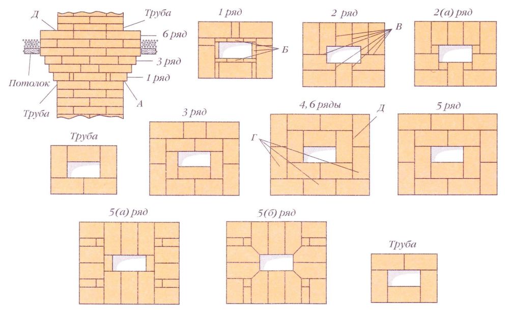
Cutting a pipe in a ceiling opening with a flue size of 13.5 × 26 cm
Keep in mind that each material has a different sediment. Depending on the height of the room and the oven, cutting will start a few centimeters higher or lower. If the cutting is one row lower, then the upper overlap will look a little wider, but since it is under the ceiling, after laying all the rows of cutting will look the same in height. There is a rule: if you do not know the size of the draft at home, then it is better to cut the cutting below the ceiling. It is more convenient to cut the pipe in four overlaps A up to 3 cm according to the template, starting from the corner bricks and aligning the top and side of the row with the rule. The size of the flue in the cutting should be the same as it was at the beginning of the masonry (in the pipe riser), therefore, in the 1st row of cutting from the inside, quarters of brick B should be laid flush with the flue. It happens that cutting without dressing with the center falls off, because they can step on it from above when they walk in the attic. Therefore, it is necessary to connect the rows with the center.
Sometimes it is advised to make overlaps in the groove of more than 6 cm. However, with such an overlap, the brick simply turns out of the masonry from pressure from above. You need to know that when laying a cutting with an overlap, even 25 mm, the hanging brick still tries to bend over the void. In the 2nd row, the masonry is connected to the middle of the pipe. It can be laid as in row 2(a), where square dice are applied to the three-quarters, but they are more difficult to make. It is good to start letting in the 3rd and 4th rows from the gas duct, then the bricks will be fixed around it with the bottom row, and it is easier to lay the outer bricks against them with an overlap, but still, the part of the brick that is let in must be maintained for several seconds until the moisture from the solution is soak into the brick. The inner seam will hold the brick well from tilting.
The division is made for the purpose fire protection so the seams should be as thin as possible. The hewn or chipped part of the brick must be ground (levelled) with the plane of the brick or with an emery stone. Before something else is chipped off from an already chipped brick, you must first level the spall. It is best to make laps in the cutting in the first three rows of 32 mm. These overlaps allow you to make a gradual expansion of the pipe with the same step on each side to half a brick plus a seam. In the process of cutting, the laying of the 4th row starts from the gas duct from a whole brick.
In the 2nd row there are six seams B from the flue to the edge of the cut. This row is below the ceiling, so such seams are not dangerous. But if this laying is done in the middle of a wooden ceiling, then with incomplete seams and in the event of cracks due to uneven settlement of the furnace foundation, there is a risk of fire. To avoid this, near the parts of the combustible ceiling, the cutting is made in rings (3-6th rows) so that the seam from the gas duct overlaps with the middle of the G brick of the second, outer, ring. Since a thermal backfill is made from combustible materials (leaves, sawdust, peat, etc.) on top of the ceiling, the ceiling cutting is placed one or two rows above the backfill.

Cutting a pipe in a ceiling opening with a flue size of 13.5 × 13.5 cm
The masonry can be finished as shown in the usual orders, but in this case the upper rows in place D will not be connected to each other and there is a feeling that they can disperse. For reliability, I did the masonry as shown in the pictures. From the top of such a row, a pipe begins, which will fix the cutting masonry. It would be nice to finish the top of the groove with 6 cm ledges around the entire groove, as shown in the 7th row, where the groove masonry was made with a pipe flue size of 13.5 × 13.5 cm.
Sometimes when laying in the middle of the ceiling opening, when the last bricks in a row are laid to each other with a thin seam, uncertainty is created in the strength of the seam. In this case, the seam must be sealed. They do it like this. The entire width of the hammer blade is inserted into the seam between the brick and the ceiling and, tilting the hammer, the blade presses the bricks closer together in the middle. An even pipe riser is laid to the roof.
Making a pipe hole in the roof
It is very important to accurately calculate the size of the hole for the pipe in the roof. Otherwise, having folded the oven, you will also have to resort to the services of a tinsmith. Much easier to take care of this in advance. When the pipe is folded to the level of the roof, it is necessary to transfer the dimensions of the pipe in the corners to the roof using a plumb line L, a hammer and a nail. It must be done from attic space(punch four holes in the roof with a nail according to the marking). By connecting four holes on the upper part of the roof with a pencil, we get rectangle B, which is a projection of the horizontal section of the pipe onto the plane of the roof. Next, you need to step back from each side of the rectangle by 7-10 cm and build another one inside it - a smaller rectangle B. If there are seams in the roofing gland D at the exit of the pipe, then they can be nailed (tumbled down) to the roof.

Corners D of the two resulting rectangles need to be connected, cut out a smaller rectangle B and cut the roof along the line connecting the corners. The resulting four strips E must be bent along the leaning bar (board) so that they do not reach a little vertical position. Then the iron will be more tightly pressed against the pipe wall. The remaining unprotected triangular voids between the sides (bent strips E) in the corners of the pipe are sealed from the inside with cement mortar, pressing the brick against them, and outside, above the iron sides, they are plastered.
Pipe laying above the roof
When laying pipes over the roof for scaffolding, I always used an ordinary wooden ladder 1. If it was not there, then I made it myself - I nailed it to a wide board wooden blocks. To keep the ladder on the roof, I nailed a strong wooden beam 2 to it at the top, which hooked it to the roof ridge. If possible, it is good to put a ladder or a board with stuffed planks on the other side of the pipe. Through the hole for the pipe in the roof, bricks were stacked on top of the stairs 3. If the stairs were on both sides, then the brick was enough for the entire small pipe. However better brick lift to the pipe from the street for two or three times. So it will be more convenient to work.
On the rung of the stairs, the first brick lies with a spoon, one edge on the roof, the other with a slight advantage on the rung, because the stairs are low. If the first row is laid with pokes, like the second, then the brick will not hold. For the second (poke) row, there is more support. All the weight goes to the stairs. The brick can be placed above, on the next crossbar, and below. On such a platform of bricks, they often put not a box, but a bucket of mortar. The wider the staircase, the wider you can put a brick column.
During the laying of the pipe, when it is already higher than the roof, it is more convenient to put a bucket of mortar behind the pipe. Periodically it is necessary to check the verticality of the pipe laying. When the house is still without a roof or there is a large space around the pipe, the pipe may bend from pressure from above. To prevent this from happening, it is necessary to temporarily nail a bar or board from below to the roof sheathing or close to the rafters to the pipe being erected, this will prevent the pipe from deviating from the vertical position.

In the place where the pipe exits to the roof, it is necessary to encircle the pipe with roofing iron to prevent precipitation from getting under the roof. To do this, above the roof on all sides of the pipe riser, an “otter” is made from the outer part - a recess where roofing iron is brought close to the pipe - a “collar”. The recess is obtained by overlapping rows of masonry on all sides of the pipe. The overlap is made at least 2.5 cm. Depending on the steepness of the roof slope, projections-laps A are made according to the number of rows in the fluff cabinet. Due to the different steepness of the roof slope, it is impossible to accurately draw a drawing of the fluff cabinet orders, this is the only place in the furnace where it is impossible to give exact orders. In order to lay out a pedestal above the roof in a pipe, and under it an “otter”, you need to make brick laps near the roof over the void. They can turn out where higher, where lower.

It is easier to lay the masonry along the U-shaped formwork 1 of three edged boards 7-10 cm wide, knocked down with small nails 2. Usually I put such formwork on the roof sheathing. The entire pipe on top of the roof is laid on a solution that is not destructible by precipitation, one row below the roof. If the roof rise allows, then the 1st row is laid on three sides at once, like the 2nd row. The rest of the masonry of the 1st row from the inside is flush with the pipe riser. All laps from the pipe are 3 cm each. From the 2nd row, laps B begin over the side walls. The height of the laps above the roof roof is at least 5-7 cm. If the height of the collar above the roof is lower than 10 cm, and the pipe is at the bottom of the roof, then heavy rains form a water stream on the roof, which can rise above the iron collar B. The water will wet the pipe and enter the room.
Collar shown only one contour line so that the masonry of the riser G of the pipe is visible. In the order of the pedestal above the pipe riser, the 1st row is placed with an overlap D only above the front wall, which is clearly visible from a different angle - in the order. I never laid out the 1st row in the middle of the cabinet in quarters, since gases go in the middle of the pipe, and when a lot of soot settles in the recess formed in the places of the missing quarters, it's time to clean the entire pipe. If you clean the pipe with a green broom, then soot will be removed from all corners. Usually quarters complicate the work, after a few years they usually fall out of the masonry into the bottom of the gas ducts. The 3rd row is laid on the 2nd row with dressing. They lengthen the laps above the side walls and make internal ledges in the side walls, expanding the gas duct in this place. So with each row in the place where the laps go, the size of the flue increases. Further along the board, laying continues with a constant overlap of incomplete bricks. 4th and 5th rows - the last before the overlap over the back wall. They are above the roof, where there will be an iron collar behind the pipe.
Since debris (dust, leaves, etc.) always accumulates behind the pipe, the iron rusts in this place, forming holes in the collar. In order to increase the durability of the collar, I suggest making one of the side walls E 3 cm longer in the 4th and 5th rows. The masonry of the back wall will go obliquely. After laying at this wall, one corner in the roof will be higher, and around the pipe you will get a gutter with an inclination, from which debris will be washed away by rain. At the same time, the laying of the back wall becomes a little more complicated, since it will be necessary to cut the rectangular parts of the brick into oblique ones. Masonry can also be done in the usual way - along the 3rd row without lengthening the wall, then the gutter behind the pipe will be without inclination. In the 6th row, the laying of the laps over the back wall is finished (shown in dotted line). The 7th row is placed exactly on the 6th row. The 8th row is let inside the pipe above the flue. From this row, the masonry is again made vertically along the pipe riser. Start laying the neck of the pipe to the desired height of five bricks in one row.
The pipe is finished with the masonry of the head from three rows with two overlaps - the 13-15th row. The masonry head is always exposed to precipitation, frost, gases. Frost freezes wet seams, and warm weather defrosts. Seams and masonry do not withstand temperature changes and are destroyed. In the masonry of the head there are many quarters of brick with thick seams. The seams get wet, and the frost gradually expands them. They become weak, and the solution spills out of the seams. To increase the life of the pipe, one should always think about how to lay the head so that almost no quarters are used, and the vertical seams are as thin as possible.
After laying on the ledges of the pedestal and the head of the pipe, an oblique packing is made of a durable cement mortar, which is good to “ironize” - sprinkle dry cement on top and smooth with a trowel. It serves to shed rainfall. Weak composition quickly collapses. Laying the neck of the pipe with sharp corners. If desired, you can chamfer the corners at the corners, as when plastering the corners. Laying the neck of the pipe with chamfered corners 4 cm on each side 3. If you chamfer less, then the beauty of the masonry will not be clearly visible from the ground. Pipe laying in this embodiment can be done in order. The corners of the pipe, like the corners of the house, are exposed to strong blows of cold winds. The wall thickness of the pipe is 12 cm. In places where corners are sheared, the thickness of the pipe is much greater (even after shearing it will be at least 14 cm).
The cutting of the corner to nothing to the chamfer of the corner begins in the 11th row, retreating from the bottom of the corner by 2 cm. From the 12th to the 1bth rows, brickwork with hewn corners is made of the same type with dressing. In the 17th row, a stitching is done, similar to what was done in the 11th row, but retreating 2 cm from the top of the fragility. The remaining 2 cm in this row make the corners more beautiful and create a cap and the best support, and masonry strength. The neck of the pipe will be eight rows, but for a higher pipe, this masonry can be continued. The 18-20th rows in the variant with corners are laid in the same way as 13-1 of the 5th rows in the variant without corners. The corners of the pipe are beveled, and there are two inlet rows in the head-cap. So the pipe looks more beautiful, but if you cover it with a galvanized iron cap, and put a rooster in profile on top, it will be even more beautiful.

Since a brick happens different size, then, before laying the head of the pipe, the 14th row is laid dry on the floor so that the masonry of the row is divided into halves of the brick. The seam between the bricks is 5 mm. If we put the last 15th row of five bricks on this row vertically to the riser of the pipe, then a protrusion of 6 cm will turn out around it. We need to divide these 6 cm into two rows, we get that in each row we need to make overlaps of 3 cm. In the upper overlapped row, the masonry is divided into whole bricks and halves, which makes it simpler.
Laying pipes already doing it in a laid out row on the floor. If the pipe is located from the roof ridge at a distance of up to 1.5 m, then it must be at least 25 cm higher than it. If the distance is more than 1.5 m, then the pipe may be low. Sometimes a brick falls off in layers from a plastered pipe. This happens when it is plastered with cement mortar. It is dense, air does not pass through it. Due to the temperature difference, condensation forms under the plaster, which destroys both the plaster and the brick. It is possible to plaster a pipe only with a solution in which there is slaked lime.
When building a private house and arranging a heating system, many homeowners are faced with the difficulty of laying a chimney. Quite often, red ceramic bricks are used for this work, which must be laid using a special furnace solution. It is about how to choose such a composition used for laying a chimney that we will talk about in this article.
Many homeowners mistakenly believe that they can use ordinary cement mortar, which was used for laying brick walls, for laying a chimney. However, experts do not recommend using it when laying a stove and a chimney. The fact is that during operation the chimney is subjected to significant thermal and chemical loads, and the usual binder mixture cannot be used in this case. It is necessary to use special heat-efficient mixtures that can withstand increased thermal loads with equal ease and are resistant to various acids.
For laying the stove pipe, it is recommended to use compositions that are normal in terms of fat content, since they are distinguished by proper plasticity and are not prone to cracks. For this work, complex in composition, consisting of several components, are used. Binders based on sand, cement with lime are very popular. Also on sale you can already find ready mixes, intended for laying bricks, characterized by excellent thermal stability.
The only disadvantage of such dry masonry mixes is that they are expensive. Therefore, many homeowners, doing such construction work, prepare the solution on their own.
You should also pay attention to the indicators of the density of the composition used. The prepared mixture should be homogeneous, the structure resembles vaguely sour cream. It should be slightly squeezed out when laying bricks, but it should perfectly hold together the materials used. For this work, the following compositions are used:
- Clay.
- Lime.
- Cement with the addition of lime and fireclay.
- Lime-gypsum.
High-quality clay compositions with the addition of cement and sand have been successfully used for chimney masonry in the past, but today they are gradually being replaced by other, high-quality and  inexpensive formulations. The clay-based composition is resistant to high temperature, however, it can be destroyed by moisture. That is why it is necessary to equip a large-sized metal umbrella above the stove pipe, which will completely prevent water from entering the stove. When using clay mortar for masonry brick stove and chimney pipes, it must be remembered that it is not recommended to use wet fresh firewood as fuel in this case. This will also lead to the failure of the chimney.
To increase the strength indicators in the preparation of a clay solution, you can add about one hundred grams of table salt to one kilogram of Portland cement. Just remember that salt must be mixed with water an hour before cooking. To check the quality of the prepared solution for brickwork the chimney, it is necessary to blind a small ball with a diameter of about 50 millimeters from the resulting mass. The resulting ball should keep its shape perfectly and not stick to your hands. Subsequently, the laying of the chimney using a clay composition is carried out according to the standard scheme.
Lime mortar for stove pipe
Lime mortars for laying stove pipes began to be used relatively recently and today they have become the main masonry material. He provided proper cooking provides excellent heat resistance, is not affected by moisture and qualitatively fastens the masonry, ensuring maximum durability of the entire structure. It is recommended to use slaked lime, sand, a small amount of cement and gypsum in lime mortar to improve the quality. Classic recipe for brickwork means one mass fraction of lime and five parts of sand. In the minimum volumetric masses, lime is added with cement. You also need to add water and stir everything until smooth. The solution should have the consistency of thick sour cream and not stick to the trowel and concrete mixer.
Using such a solution, intended for laying the stove pipe, it should be remembered that its quality directly depends on the quality of the lime.
That is why it is recommended to use boiled lime, which is poured with water, after which it is kept until it is completely extinguished. It is best to carry out the lime slaking procedure in plastic barrels or pre-dug pits sheathed with boards. Only after that you can start preparing the composition necessary for brickwork.
cement-based mortar
The cement-based mortar is different increased strength and ease of preparation. Brickwork, made on the basis of cement, is strong, durable and resistant to soot and other aggressive substances. To date, cement-based masonry mortar, due to the affordable cost of the components used and the ease of preparation, has become the most widespread.
The composition for the chimney above the roof is made of cement, sand and the addition of water. The ratio of cement and sand can vary from one to one to one to six. It should be remembered that such a solution sets quickly, and an hour after preparation, it begins to lose its strength and elasticity. Therefore, you should not cook it in large batches, but use it immediately after cooking for 30 to 60 minutes.
High-quality preparation of cement mortar
We spill the used cement and sand through a sieve to completely get rid of lumps. Mix sand with cement until a homogeneous mass is obtained. At the final stage of cooking, add water, which will allow you to get the desired consistency. Just remember that such a mortar based on cement and sand alone does not have proper thermal stability, therefore it is not recommended to use it for laying a chimney in close proximity to the stove.
 If you need to prepare a heat-resistant solution, then you will need slaked lime, which is diluted with sand in a ratio of one to one. Next, 0.5 parts of cement are added and everything is thoroughly mixed. A properly prepared mortar of lime and cement has excellent thermal stability, which allows it to be used for laying the lower part brick pipe. Also, to increase the strength of the material, fireclay can be used, which improves the thermal strength of the composition.
When using cement for mortar preparation, it is recommended to use a material with a strength index of at least M400. This will ensure the necessary strength of the brickwork and its durability. The thickness of the seam can vary from five to ten millimeters.
Lime-gypsum mortar
Inexpensive to produce lime gypsum mortar actively used in the decoration and plastering of the stove. By adding cement and a large number lime, such a composition can easily be used for laying a brick chimney pipe. The advantage of its use is the ease of working with it and accelerated setting. It is only necessary to correctly calculate the ratio of components and achieve the desired consistency of the prepared mass.
Before the first heating of the stove, you need to thoroughly dry the masonry, which will eliminate the risk of cracking the chimney.
Conclusion
By correctly selecting the components used and correctly preparing the mixture for laying pipes, you can equip high-quality, durable and resistant to various loads chimney pipe. Such a properly built stove will be able to effectively heat the room, and the homeowner will be relieved of any difficulties with its use.
install the valve bowls on a layer of asbestos with resin thick mm, applied to the supporting surface of the masonry of wells;
the space between the bowl and the masonry along the entire circumference of the bowl, as well as the outer masonry of the gas flues from the place of installation of the valves to its adjoining to the walls of the regenerators over the gas-sealing coating - carefully compact with a mixture of sand and dehydrated coal tar. The mixture should be applied in separate layers to a thickness of mm and compacted with hot rammers.
3.3. When laying the lining of regenerators, slag tanks and the hearth of the furnace, the dressing of vertical joints must be performed by laying bricks at an angle of 90 ° in rows of lining and hearth adjacent in height.
Masonry of regenerators and slag tanks
3.4. The thickness of the leveling layer of mortar for laying the lining of regenerators should not exceed 15 mm. Clay pavement of regenerators ordinary brick should be placed on the board.
Bricks of the lining of fireclay bricks in the upper row should be laid on the edge across the movement of gases with transverse seams bandaged.
The deviation of the regenerator lining surface from the horizontal is allowed no more than 5 mm over a length of 2 m.
Laying the lining of slag deposits must be done with bricks on edge. Laying of linings, walls and arches of regenerators and slag pits should be carried out with mortar.
3.5. The laying of the walls of gas and air regenerators must be carried out simultaneously. On the separate sections masonry is allowed with a stepped chisel, but not more than ten rows.
3.6. Laying of slag wall cladding should be carried out in ligation with the main walls.
The masonry of the ends of the pass wall must be tied with the masonry of the walls of the regenerators and slag tanks.
Wall masonry, made of insulating and ordinary clay bricks, is not tied up with refractory masonry, it should be carried out with a lag or lead from refractory masonry by no more than three rows.
3.7. The laying of the under attachment arches should be carried out in mortar, and the attachments should be laid dry with dressing of the seams and strict observance of the verticality and squareness of the cells.
The deviation of the packing cells from the design dimensions should not exceed 8 mm. Bricks of the nozzle, resting on two supports, should go onto the underlying brick by at least 25, and when laying magnesite-chromite bricks - by at least 65 mm.
The deviation of the upper plane of the nozzle from the horizontal should not exceed 8 mm.
In the jackets of regenerators, the windows for purging and inspecting the nozzle must exactly match the channels in the nozzle. A gap must be left between the lining of the packing and the walls of the regenerator chambers.
3.8. In places of pinches, the vaults should be laid in rings. When laying magnesite bricks, the first round of the slag arch is performed dry, and in places of pinches - using gaskets and pins.
The formwork should be removed at the end of the laying of the breakout on the vaults.
3.9. The first layer of sealing coating on the second arch of the regenerator and slag vaults should be applied before the furnace is heated, and the subsequent layers and insulation of the vaults with diatomite bricks should be applied after two or three heats.
3.10. Laying of the suspended vault of regenerators and slag tanks should be carried out after the laying of the walls. The gap between the vaults and walls should be temporarily filled with a sealing mortar, and after heating the furnace, it should be filled with bricks on the mortar.
A gap of 15 mm should be left between the magnesite and high alumina masonry of the vault, in which a corrugated steel gasket should be laid.
In the laying of a suspended vault made of high alumina bricks, the protrusions of bricks in a row and between rows should coincide with the depressions of neighboring bricks.
The transitional sections of the junction of the flat vault of slag pits with the vertical channel should be assembled after laying at least 10 rows of the flat vault adjacent to the transitional section.
Masonry working space oven
3.11. The insulation of the steel structures of the hearth and slopes of the furnace with asbestos cardboard must be completed before the laying of the furnace.
The laying of each row of the hearth should be done in dressing, with filling the joints in the masonry of lightweight fireclay and fireclay bricks with fireclay powder with a grinding size of up to 1 mm.
The laying of the rows of the hearth should be started alternately from the transverse and longitudinal axes of the working space in compliance with the requirements of clause 3.3. of this manual.
The slope of the laying of the hearth to the steel tapping hole (if it is provided for by the project) must be made by laying bricks in ledges without grouting and leveling these ledges with a layer of chromium or magnesite mass with a seal.
3.12. The first row of magnesite bricks along the chamotte masonry of the hearth should be laid according to the project on a die or rib, the subsequent rows - on the rib or end, and the top row - on the end, with ribs across the bath, with the exception of furnaces with a capacity of 5 tons, where the top row is laid on the rib.
Seams in magnesite masonry must be carefully filled with dried and sifted magnesite powder with grains no larger than 0.5 mm.
Longitudinal and transverse expansion joints in the rows of masonry, the hearths must be covered by the overlying row. Temperature gaps under the transverse slopes must be filled with magnesite powder (the gaps under the longitudinal slopes are not covered).
3.13. The magnesite laying of the hearth within at least 1 m on both sides of the axis of the steel tapping hole must be made close to the furnace fittings; in this case, the thermal expansion of the masonry in the region of the hole must be compensated by an increase in the thickness of the joints in the masonry in front of the hole.
3.14. Laying of slopes and walls must be done in longitudinal and transverse bandaging with filling the joints with dry sifted magnesite powder. Between the reinforcement and the insulating masonry, asbestos cardboard should be laid.
The laying of the back wall must be started from the steel tapping hole, while the magnesite or chromium-magnesite laying within at least 1 m on both sides of the hole axis should be carried out close to the furnace fittings.
3.15. The laying of the arches must be carried out in separate rounds with the laying of bricks on the edge in a bandage and filling the joints with finely sifted powder from a material of the same type as the brick.
The locks in the arches of the filling windows should be hammered in simultaneously in all arches.
3.16. When laying the working space of an acid furnace, the following special requirements must be met:
lay the bottoms of slopes and walls with filling the joints with dinas powder, dried at 60 ° C;
the slope of the hearth to the steel tapping hole is to be carried out with a brick undercut in the lower rows of the hearth;
expansion joints in the dinas masonry of walls and slopes should be placed staggered along the entire height and thickness of the walls and slopes and filled with burn-out gaskets in accordance with the project. Expansion joints in the masonry of columns, steel-cutting and slag holes are not left.
Masonry vault workspace
3.17. The laying of the vault must be carried out in rings, starting from the transverse axis of the furnace towards the heads. The rings must be tightly fitted to each other with a gap between them of no more than 2 mm. Rusting of bricks in the rings of stationary open-hearth furnaces is not allowed.
Circled formwork of the vault should not rest on the caissons of the gas heads.
3.18. The basic location of the hangers for bricks in the rings should be determined when laying the first ring and the hangers in the remaining rings should be installed on it. The deviation of the hangers from the axis of the row along the longitudinal axis of the furnace should not exceed 25 mm.
Suspension rods of each ring should be located in the same vertical plane and directed radially to the roof surface.
The deviation from the design dimensions of the gasket and suspension steel plates should not exceed: in width and length ± 1 mm, in the location of the holes ± 1 mm and in the diameter of the holes ± 1 mm; reinforcement pins - along the length ± 1 mm and along the diameter ± 1 mm. The plates must be even, without burrs.
It is not allowed to install two gasket plates in one seam.
3.19. One lock must be installed in each ring, which must be driven in immediately after the ring is completed, and in order to avoid distortion of the ring, the laying of subsequent rings should be made from the heel supports in ledges.
3.20. Hanging and thrust reinforcement should be mounted at the end of the masonry section of the arch with a length equal to the length bearing corners.
3.21. When the vault is supported on the formwork, the gaps between the upper edge of the thrust (restrictive) tubes and the lower flange of the arc beams or crossbars in the vault bundle should be equal to 15 mm with a gradual decrease towards the heels to 0.
To determine the position of the vault after the removal of the formwork and its growth when the furnace is heated before the formwork is removed, beacons must be installed along the longitudinal axis of the vault. The measurement results must be recorded in the furnace acceptance certificate.
4. CONVERTER LINING
4.1. The thickness of the joints in the lining of the converter should not exceed 2 mm, except for the lining made of silica bricks, where the thickness of the joints is allowed up to 5 mm.
4.2. The lining of the working and reinforcing layers, as well as the bottom of periclase-spinel, magnesite-chromite and magnesite bricks, should be carried out dry with filling the joints with powder from a material of the same type as the brick, with the exception of the last two rows of the neck, the outlet and the first two rows of the body lining, which must be made on a semi-thick solution prepared from the same powder: fractions less than 0.5 mm 85%, refractory clay 15% and water.
The lining of resin-dolomite or resin-magnesite products should be made dry, without backfilling the seams; laying the bottom layer of the bottom from fireclay bricks - keep dry with filling with fireclay powder with a grain size of not more than 1 mm.
4.3. The laying of the working and reinforcing layers and dense packing of the intermediate layer and the gap between the hull and the reinforcing layer with resin-dolomite or resin-magnesite mass should be carried out simultaneously.
4.4. In converters with a removable bottom, the first two rings of the body should be assembled on a temporary flat formwork (false bottom) installed instead of the bottom. The rings must be tightly wedged so that when the formwork is removed before the bottom is installed, it cannot fall out.
The removable bottom is installed on the mass provided for by the project with a thickness of layers after drying the casing lining.
4.5. In the lining of fired refractories, the expansion joints provided for by the project must be made during the laying process by installing wooden or roofing sheets 5 mm thick. In the laying of the working layer of resin-dolomite, resin-magnesite products, expansion joints are not performed.
5. LAYING FURNACES FOR HEATING AND HEAT TREATMENT OF METAL
5.1. In the laying of furnaces for heating and heat treatment of metal, the design thickness of the joints indicated in Table 3.
Table 3
Elements of furnaces for heating and heat treatment of metal | ||||
joint thickness, mm |
||||
ventilation ducts hogs and sub-hearth masonry of ordinary clay bricks | ||||
Furnace hearths in areas of possible slag formation and hearths not protected by packing | ||||
Other pods | ||||
Vaults, arches and covers of all types at a temperature of the working space above 1400 °, and beam ones with a span of more than 4 m | ||||
Other vaults, arches and covers | ||||
Furnace walls working at a working space temperature above 1400 °, and dividing walls | ||||
Other walls and supporting pillars | ||||
Burner loopholes | ||||
External insulation of furnaces(vault, walls, hearth) of brick: | ||||
lightweight refractory | ||||
diatomite | ||||
ordinary clay |
Masonry stoves for heating and heat treatment metal should be performed on the solution, with the exception of places specifically specified in the project.
5.2. Deviations from the design dimensions of the masonry in the outer dimensions of the furnace, as well as in the width of the ventilation ducts, should not exceed 10 mm.
Deviations from the design dimensions of the gaps in the furnace masonry, intended for the free movement of the hearth and furnace mechanisms, should not exceed 10 mm, unless otherwise specified in the furnace design.
5.3. The shells of the working space of furnaces operating with controlled atmospheres must be tested for tightness before laying.
5.4. After the masonry is completed, the ventilation ducts must be cleaned of mortar residues and construction debris and handed over according to the act for hidden work.
5.5. The laying of the furnace hearth must be carried out with dressing of vertical joints in compliance with the requirements of clause 3.3. of this manual. The deviation from the horizontal of the diatomite masonry of the hearth should not exceed 5 mm for its entire length.
The upper rows of hearth masonry made of fireclay and chrome-magnesite bricks should be laid on edge (in pass-through furnaces along the metal path), close to the furnace walls without dressing with them.
When installing embedded steel parts in the under and walls, the gaps provided for by the project must be left in the masonry.
5.6. Expansion joints in the hearth masonry of magnesite or chromium-magnesite bricks should be arranged every 3-4 bricks by laying roofing or wooden spacers 2 - 3 mm thick and overlap with overlying rows. Chromomagnesite and magnesite bricks should be laid dry with the joints filled with pre-dried magnesite powder. Temperature joints in the walls should be of the lock type. Expansion joints are not left in the insulating masonry. In walls with burners, expansion joints are left in the middle, between the burner tunnels.
5.7. The masonry of walls from two or three layers of refractory products of the same type (high-alumina, fireclay, lightweight fireclay) must be carried out simultaneously and tied together along the entire height of the walls. In this case, more refractory products should be produced in a layer of less refractory ones. The outer layer of diatomite brick with a refractory layer is not bandaged. Gaps between diatomite and refractory masonry and between masonry and metal frame should be filled with a thick solution.
In furnaces with a suspended vault, the upper row of walls should be laid out after the vault has been assembled.
The installation of burners and peepers must be carried out, as a rule, before the laying of the walls. The deviation of the inclination angle of the burner tunnel from the inclination angle of the burner must be within ± 1°.
5.8. The deviation of the surface of the brickwork under the sand gates from the horizontal should not be more than ± 10 mm for the entire length of the gate.
5.9. When laying heating wells, the curvature of the masonry walls must be checked with templates every five rows of masonry. Blockages of masonry walls inside the cells are not allowed; deviations from the design dimensions of the cell along the length and width are allowed within ± 10 mm.
The top of the sand seal masonry should not exceed the design mark. The gap between the lining of the cell and the bottom of the lining of the cover must be at least 50 mm.
Chromite stuffing of the hearth, backfilling with coke and stuffing around the neck should be done immediately before putting the wells for drying.
6. BLANKING OF RING HEATING FURNACES
6.1. To the masonry of ring heating furnaces in accordance with the instructions of SNiP III-24-75 "Masonry industrial furnaces and chimneys» should be started after the commissioning of the foundations, furnace and hearth frames (including under-hearth water seals), fuel combustion devices and the hearth rotation mechanism according to the act. An exception is the laying of internal hogs, which must be completed before installing the furnace frames and the hearth.
The lining of smoke extractions within the casings is also carried out after delivery according to the act of the latter.
The concentricity of the oven and hearth frames must be checked by rotating the hearth; while the distance between the beacons installed every 2 - 3 m on support rings oven walls and hearth, should not deviate from the design by more than 10 mm.
The dimensions of the annular gap between the frame and the hearth should not deviate from the design ones by more than 15 mm along the outer ring and 10 mm along the inner one.
Metal elements should not protrude towards the masonry beyond its design dimensions.
6.2. In the laying of annular heating furnaces, the design thickness of the joints indicated in Table 4.
The laying of the furnace must be carried out on the solution, with the exception of the suspended arch, which is typed dry.
6.3. The supporting cooled pipes of the partitions must be mounted at the end of the laying of the walls, for which mounting openings must be left in the stacks, and the sectors of the arch above the partitions must be assembled after the laying of the latter.
6.4. The laying of internal hogs should be done before the installation of the frame. Borova, smoke extraction and gas pipelines should be laid out in accordance with the instructions of SNiP III-24-75 "Laying industrial furnaces and chimneys".
Table 4
Elements of ring heating furnaces | ||||
joint thickness, mm |
||||
Smoke extractors, brickwork: | ||||
ordinary clay | ||||
fireclay | ||||
diatomite | ||||
Ring under, masonry: | ||||
diatomite |
The technology of laying a brick chimney in itself is quite simple and understandable, since, unlike the brick oven itself, the pipe usually does not have internal channels that are complex in configuration. However, despite the relative simplicity of the design, one cannot but take into account the enormous importance of this department of the furnace, since the quality of the heating of the house and the safety of both the building itself and the people living in it directly depend on it. Therefore, in order for all the work to be successful, it is necessary to approach it with the utmost care, relying on the recommendations of experienced craftsmen and on the developed and tested design schemes.
When erecting a chimney, it should be remembered that the evenness of the inner walls of the channel is no less important than aesthetics. outdoor masonry. Not only the stability of the required draft in the furnace depends on this circumstance, but also the duration of operation of the chimney without cleaning, since the smoke rising through the pipe leaves on smooth walls, without protruding mortar and deep seams, a much smaller amount of fuel combustion waste, and the channel overgrows much slower.
What are brick chimneys?
Chimneys of brick ovens can be of different types, depending on the place of their installation, the design of the furnace, and also on how many heaters will be connected to the pipe. So, there are three main types of chimney brick pipes: these are mounted, root and wall.
- Wall-mounted chimneys . The most widely used constructions are packed pipes. They are good because they are compact and do not occupy at all additional space indoors, but are simply a vertical extension of the oven.

They are erected on top of the last row of bricks covering the furnace, around the left hole. The pipe is then passed through attic floor, attic, truss system and rise above the roof.
- Indigenous chimneys . This type of pipe is installed in cases where it is planned to connect a metal stove to it, or several heating appliances located on one or even several floors.

In addition to metal, brick ovens can also be connected to such a pipe. This type of chimney is especially convenient if it is necessary to build two stoves in the house in neighboring rooms. For example, a kitchen needs an oven with hob, and for the next room - only heating. In order not to lay out a separate pipe for each of them, a root chimney is built between the rooms, to which both heaters are connected. Not only two, but also three or four stoves located on different floors of the house can be connected to a pipe of this type. In any case, it is necessary to calculate the size of the internal chimney channel very accurately, otherwise normal draft may not be ensured when several devices are operating simultaneously. The answer to the question why may be different.
- Wall chimneys line up near the main (external or internal) walls or are built into them. They can be used, just like the main ones, to connect several furnaces located on different floors of the building.

The convenience of this design lies in the fact that it is, as it were, outside the living quarters, without occupying their area. For example, on the first floor of the house a fireplace can be built and connected to the wall chimney (there the pipe will be more like a wall chimney according to the principle of structure), and on the second floor a chimney pipe is embedded metal furnace(in the same way as in the version with the root requirement).
The disadvantages of this version of the chimney are the considerable cost of the project and the complexity of the work. Firstly, the construction of this structure will require much more building material. Secondly, the chimney, if it is partially on the street, requires serious insulation measures, otherwise in winter, with temperature changes, condensate will form in the internal channels, which will significantly reduce the efficiency of the heater. Therefore, if this version of the chimney is chosen, it would still be wiser to sacrifice the area inside the premises and lead the pipe along the inner wall of the house.
Parameters of brick chimneys
The main sections of the brick chimney
A brick chimney is divided into departments that have an owl purpose and are named differently. These features must be immediately clarified so that in the future it will be easier to understand the description of the work on the construction of the pipe.

1 - Pipe head. Laying out this part of the chimney, the bricks are shifted into outside to get a kind of "visor", as if hanging over the lower sections, partially protecting the pipe walls from atmospheric precipitation.
2 - The neck of the pipe is located immediately below the head and has the same perimeter over its entire height, without protrusions, extensions or narrowing.
3 - "Otter" has more complex scheme masonry, as it has a protective function. Firstly, the laying of the "otter" hanging over the gap formed at the junction roofing material and the walls of the pipe, closes it from the penetration of precipitation, and forms a space for the installation of a waterproofing material. Secondly, its expanded walls become a guarantee of safety - at the place of passage through the roofing, due to the increased thickness, a required level thermal insulation.
4 - A metal or other sheet (apron), mounted in the lower part of the otter, forms a kind of ebb, which closes the junction of the brick wall of the pipe and the roofing material.
5 - "Fluffing" - this expanded part of the pipe, located in the area of \u200b\u200bits passage through the attic floor. The walls of the "fluff", like the "otter", have greater thickness, than others flat areas chimney - this is necessary for fire safety, since the attic floor very often consists of flammable materials, and they cannot be allowed to overheat.
6 - Roofing structure.
7 - A riser is a straight pipe section that has a flat masonry over its entire height and is located in attic space from "fluff" to "otter".
8 - Attic floor.
9 - An umbrella cap is often fixed on top of the head, which will protect the internal chimney channel from water and debris entering it.
You may be interested in information about what is
The main function of the chimney is to effectively remove combustion products from the combustion chamber into the atmosphere. To do this, the chimney is connected to numerous channels located in the furnace structure, with which it must interact harmoniously. If the stove and chimney are built correctly, in accordance with the developed parameters, then during the operation of the heater, good draft should be created inside the channels, which will contribute to the timely removal of smoke to the street. However, at the same time, this should not lead to the fact that the heat generated by it will fly out of the furnace literally “into the pipe”. In a word, everything needs a “golden mean”.

Cross section of the chimney channel
For selection correct parameters section of the chimney channel, you need to take into account the power of the furnace, as well as the size of the combustion chamber. The flue ducts will remain clean longer if their inner walls are made smooth, without protrusions and sagging of the solution.
For this reason, during the laying of bricks, the excess masonry mortar that has come out in the seams must be cleaned off not only from the outer, but also from the inner walls. Some owners of houses equipped with fireplaces or stoves also use another way to achieve the smoothness of the walls of the channel - they install a ceramic pipe called an inlay inside the brick chimney.
The advantage of this design is not only that the inlay has absolutely smooth inner walls. It is round in cross section, that is, it has no corners, which means that the smoke flows will not encounter obstacles in their path and, at the same time, unnecessary turbulences and the “back draft” effect will not be created.

On the right of the illustration, the “ideal” movement of the flow of hot gases is shown, which are twisted into a regular spiral in a round pipe and do not meet resistance.
In addition, it is necessary to take into account the fact that chimneys with a large width, which are still installed in old houses, often have bad traction. This is due to the fact that the air heated in the furnace in large space inside the pipe, cools down quickly, which leads to the formation of condensate, which contributes to a decrease in traction, as well as smoke in the premises, and the channel quickly overgrows with soot. To heat a stove with such a chimney design, you will need to use too much fuel. Therefore, it would be most rational to fix them by dismantling a wide upper part chimney, then narrowing the shaft and installing a round or square with rounded corners, ceramic, metal or asbestos insert into it.

Now from the form - to linear parameters. The size of the internal section of the chimney channel is one of the most important characteristics, since the efficiency of the furnace directly depends on this. The correct ratio of the power of the heater and the dimensions of the pipe section must be observed. Another guideline for determining the correct size of the channel can be the opening of the blower door - in any case, the cross section of the pipe should not be less than the blower hole.
The cross section of the chimney shaft, relative to the size of the combustion chamber window, can be determined as follows. For fireplaces with an open firebox, the size of the chimney opening is on average 1:10. However, depending on the shape of the section and the height of the pipe, this indicator may vary in one direction or another. Approximate values of the cross-sectional area of the channel (in percent) are shown in the table below.
Ratiof/F in % (f is the cross-sectional area of the chimney channel;F is the area of the combustion chamber window)
| Pipe height, m | Sectional shape of the inner channel of the chimney pipe | ||
|---|---|---|---|
| ROUND | SQUARE | RECTANGULAR | |
| 5 | 11.2 | 12.4 | 13.2 |
| 6 | 10.5 | 11.6 | 12.3 |
| 7 | 10 | 11 | 11.7 |
| 8 | 9.5 | 10.5 | 11.2 |
| 9 | 9.1 | 10.1 | 10.6 |
| 10 | 8.7 | 9.7 | 10.2 |
| 11 | 8.9 | 9.4 | 9.8 |
It is clear that in addition to the size of the furnace window, it is also necessary to build on the reasonable height of the pipe - it will look absolutely ridiculous, for example, a huge 10-meter pipe on the roof of a small squat country house.
The calculation itself is easy. According to the table, based on the height of the pipe and the shape of its internal channel, the optimal f / F ratio is determined. Then, based on the area of the furnace window, it will not be difficult to determine the area of \u200b\u200bthe chimney channel. Well, then, using geometric formulas, it remains only to bring the resulting value to linear dimensions - the diameter for round pipe or the length of the sides for a rectangle.
This calculation algorithm is implemented in the calculator below.
The brick chimney is essential element furnace heating system. It removes combustion products and creates thrust for intake. fresh air into the furnace of the heating device. Brick chimney laying - complex building process. It requires certain skills and knowledge.
What are brick chimneys - requirements, size, configuration
There are three types of chimneys.
- Mounted construction. She continues to bake. Such a chimney is mounted on a concrete pipe fixed on the ceiling. Its slab is reinforced and must have a thickness of at least 5 cm.
- Root construction. A separate foundation is being built for it. The root pipe is rarely used and only in cases where it is impossible to make a chimney of another type.
- Wall outlet channel. It is built in the internal load-bearing walls of brick or stone.
Sometimes the construction of a wall chimney is carried out in an external load-bearing wall. Then additional work needs to be done:
- Thicken the wall from the inside (in the form of a pilaster) in the area where the pipe will pass.
- Stop hypothermia of the chimney, it will reduce draft due to steam condensation. To do this, it is necessary to maintain the required distance from the pipe to the outer plane of the bearing wall.
What to consider when building a chimney
Pipe laying should be carried out so that between it and outside there was a sufficient distance from the load-bearing wall - see the table with dimensions.
Chimneys are not allowed to be laid out in the corners of rooms and in areas where walls intersect. If the building is residential, the wall thickness of the pipe must be at least 10 centimeters. Complete tightness of the structure should be ensured; it should not let combustion products through.
Often the house is made of concrete, cinder and foam blocks, a silicate variety of brick. In this case, the sections of the walls along which the chimney will pass must be laid out of red brick. Their minimum thickness should be 12 cm. This requirement also applies to piers, partitions between smoke-removing channels.
Watch the video
Before you lay out a brick chimney with your own hands, you should consider fire safety standards:
- the gap from the outer plane of the chimney to the walls of flammable materials must be at least 40 cm.
- in the areas of the passage of the chimney through the ceilings, it is necessary to make thickenings (edge).
The chimney channel along its entire length should be assembled so that its dimensions inner space were constant.
Structure height
The vertical length of the pipe most of all affects the efficiency of traction. A well-built chimney should have a height of at least 5 m. Great importance it also has a height difference between the roof plane and the pipe head.
- The top of the chimney must be flush with the ridge. Or rise slightly above it at a distance of no more than 3 m from it.
- If the roof is flat, then the smoke outlet should rise above it by at least 1.2 m.
- The distance from the grate of the furnace to the pipe mouth must be at least 5 m.
- The height of the chimney above the roof depends on the point of its exit relative to the ridge or parapet. This value varies from 0.5 to 1.5 m.
Construction cross section
The dimensions of the chimney must be no less than the cross section of the outlet pipe of the stove. It is necessary to determine the dimensions of the smoke channel of the structure, based on the heat output of the heating device.
The cross section of the channel must correspond to the volume of combustion products passing through it and be not less than:
- 13 × 13 cm for stoves with heat output up to 3.5 kW;
- 13×25 cm for analogues with heat transfer more than 3.5 kW;
- under the Russian stove, which has a large portal, you should fold a brick pipe with a section of 26 × 26 cm with your own hands.
Which brick is better to use
 High-quality work on pipe laying is possible only with the use of the best materials. For the construction of a chimney structure, carefully burnt red full-bodied kiln bricks. Suitable for work and refractory fireclay blocks. The grade of the material must be at least M-200.
When a brick chimney is laid with your own hands, you need to choose evenly painted blocks with clear edges. In this case, they can be placed on a minimum layer of mortar. The blocks must be single, that is, have dimensions of 25 × 12 × 6.5 cm.
When moving the chimney to the roof, single and double silicate bricks of the M-150 brand can be used. They have high level frost resistance.
What mortar is used for masonry
When working, the stove-maker can use different masonry mixtures:
- Clay-sand mortar is used for laying red brick. Its proportions are 1:2. If the clay is very oily, then 3-4 volume fractions of sand are added.
- When installing refractory blocks, it is kneaded masonry mortar from refractory clay, fireclay and sand. The proportion of the mixture is 1:1:2.
- To install the chimney in the attic, you can use a cement-lime-sand mixture in a ratio of 1:1:2.
- For roof top can be applied cement-sand mixture in a ratio of 1:2.
The mortar for laying the stove chimney after mixing it with water should have a creamy consistency.
masonry rules
The cross section of the structure must be a multiple of the dimensions of the bricks. The thickness of the outer pipe walls of the wall-mounted structures must be at least half a brick. Thickness external walls the bottom of the root structures for greater stability should be equal to a whole brick with a transition at the top to half a block.
Air ducts inside the structure should be placed in a vertical direction. It is impossible to mount hogs horizontally at the level of attic floors. This is required by fire safety regulations.
Each stove must be equipped with its own chimney. Rarely, a project allows two heaters to be connected to one channel. They should have a single-level arrangement, with a height cut of 75 cm or more.
Watch the video
When installing two heaters (or a stove and an exhaust network), two channels can be connected in one riser. Their sizes remain the same. However, the installation of a two-channel chimney with a half-brick cross-section of half-brick channels is done in incomplete blocks. Five solid and two ¾ bricks are placed in each row. In this case, a reliable ligation of the masonry is achieved.
Mounting double design(chimney and ventilation duct) with the size of the channels half per solid block, made with eight bricks. If it is carried out when alternating even and odd levels, it will not be possible to connect the delimiting partition with masonry outer wall. Therefore, the alternation must be done through three rows.
The first level is assembled from eight solid blocks. In the second, five whole and four ¾ blocks are placed. With this layout, the reliability of the structure increases.
Design features and pipe departments
Before you start laying a brick chimney with your own hands, you should study its design:
![]()
- The first part of the chimney is the lower neck of the structure. She is placed on her shoulders. A valve is mounted in it. When mounting the neck, the bricks are tied up.
- Fluff is laid at a distance of 5-6 brick levels from the ceiling. This extension goes up to the attic.
- The part of the device that is laid out with one's own hands in the under-roof room is called the riser. It goes to the base of the roof.
- An otter is laid out from the roofing. It expands on all sides by at least 10 cm. This element The device prevents precipitation from entering the house.
- Next, the neck is laid out. Its dimensions are the same as those of the main pipe trunk.
- Then the cap is placed. A deflector is mounted on it, which protects the chimney from precipitation.
Stages and process of laying a brick stove chimney
You should have a chimney diagram with its order in your hands. According to it, you must carry out the construction.
Watch the video
Here step by step process masonry stove chimney:
- Prepare tools, materials and solution.
- Take measurements to the gate and fluff.
- Start laying blocks (mortar thickness should be 5-10 mm) pipes from the stove. Check the evenness of all rows with a level in all planes. After 3-4 levels, clean the channel from excess solution.
- Fix the frame at the gate mounting point. It should not disturb the position of the top of the bricks. Therefore, cut a recess in them according to the dimensions of the frame.
- Continue the construction of the structure to the level of the fluff. Calculate the number of rows that will need to be laid out to bring the fluff to the required size. Please note that in one row, the perimeter of the pipe increases by ¼ of the block width. The fluff should fit snugly with the floor beams. When they are located at a distance from the chimney structure, make persistent frames.
- Next, in order, mount the fluff. It can be made square or rectangular.
- For the calculated number of rows, go from fluff to the main dimensions of the riser. Bring it to the roof.
How to make a hole for a stove chimney in the roof

![]() The dimensions of the hole in the roofing should be calculated accurately. Having laid the chimney up to the roof, use a plumb line and a hammer with a nail to mark angular dimensions roof structures. Do it from the side of the attic.
The dimensions of the hole in the roofing should be calculated accurately. Having laid the chimney up to the roof, use a plumb line and a hammer with a nail to mark angular dimensions roof structures. Do it from the side of the attic.
Connect the holes punched with a nail with a pencil. So you get a rectangular projection of the section of the structure on the surface of the roofing. Then count 10 cm from all sides of the figure and draw a small rectangle inside it.
Connect the corners of the figures and cut out the smaller one by sawing the coating along the lines connecting the corners. Unscrew the resulting four strips along the leaning board. Do this so that they almost reach the vertical. Then the roofing will tightly press against the wall of the chimney fixture.
Cover the remaining unprotected triangular gaps between the strips at the corners of the chimney inside with mortar, leaning bricks against them. Do the same outside.
Placement of the chimney above the roof
At the level of the roofing, begin to mount the otter. The instruction says that it is more difficult to lay it down than fluff. The building must be expanded carefully and gradually. Taking into account the slope. When laying a brick chimney with your own hands, it is required to increase the stability of the structure. Therefore, wall steel plates into the otter and fix them to the rafters.
File the ends of the blocks. So you reduce the gap between the otter and the roof. You can do it differently: between the bottom of the pipe element and the roof lining, put sheet metal. It will not allow precipitation to seep onto the rafters and into the attic.
Installation of the chimney is completed by arranging the head and installing a deflector on it.
Conclusion
Watch the video
Laying a brick pipe with your own hands is a complex and time-consuming process. Before him, it is necessary to carry out calculations and draw up a diagram of the structure. When laying, you must strictly adhere to it and follow all the rules of construction.